

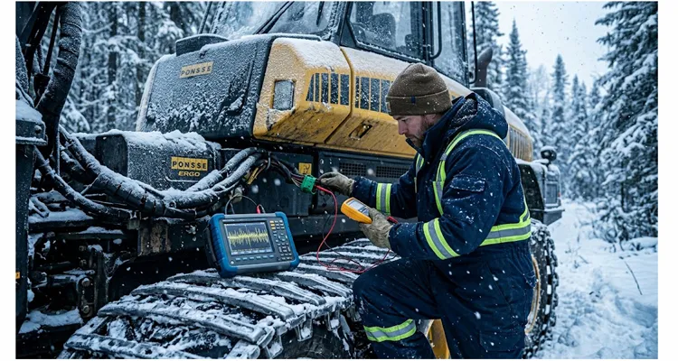
It was 14°F and the snow was coming down in thick, wet clumps somewhere in a spruce block north of Thunder Bay. I was standing on the track of a 2018 Ponsse Ergo harvester that had decided to park itself mid-cycle. The head wouldn’t feed. The dash showed one active fault: SPN 639 FMI 9. The operator, a guy with 19 winters in the cab, shrugged and said, “Came on twice this week. A key cycle cleared it. Now it won’t budge.”
That call turned into a six-hour diagnostic job that taught me more about CAN bus integrity in forestry iron than any training manual ever could. If you’re reading this, I’ll assume you’re either staring at the same code, building a diagnostic kit for your fleet, or just tired of throwing sensors at a machine that keeps derating. This guide walks through exactly how I approach SPN 639 FMI 9 on timber equipment — no marketing fluff, no AI-sounding filler, just the stuff that works when you’re kneeling in frozen mud with a multimeter and a laptop.
What SPN 639 FMI 9 Actually Means on a Forestry Machine
On the Ponsse Opti4G display, the code reads out as “Engine Speed – Abnormal Update Rate.” The SAE J1939 identifier behind it is SPN 639, broadcast inside PGN 61444 from the engine ECU‘s heartbeat message. FMI 9 doesn’t mean the crank sensor lost signal. It means the CAN frame carrying engine RPM never arrived, arrived late, or arrived with enough corrupted bits that the receiving controller rejected it outright. In a harvester, I’ve seen the head controller log this at exactly the moment the boom hit full extension — the RPM value froze on the display for 400 milliseconds, then the feed rollers stopped dead. That’s the difference between a sensor fault and a network timing fault, and mistaking one for the other is the fastest way to waste a service call.
This isn’t a sensor out-of-range fault. It’s a CAN network health problem. On a forwarder or feller-buncher, the engine ECU might still run fine with no warning lamps, but the transmission controller or the head logic suddenly loses synchronization with RPM. You get derates, blocked functions, hydraulic interlocks that feel random, and sometimes a dead pedal.
Key nuance for forestry: unlike an on-highway truck, a timber machine has multiple vibration sources, constant twisting of the chassis, and harness routing that snakes through articulation joints, saw-box compartments, and toppled-tree impact zones. An intermittent CAN fault here will almost never reveal itself in the shop bay. You diagnose it in the cut block, preferably when it’s misbehaving. As I’ve documented extensively in my field notes on forestry J1939 harness failures and field repairs, the combination of vibration, moisture, and physical impact creates failure signatures you simply won’t encounter in on-highway applications.
Where SPN 639 FMI 9 Tends to Show Up
Over the years I’ve logged this fault code on a pretty specific list of equipment and conditions:
| Machine Type | Typical Trigger Moment | Observed Frequency |
| Wheeled harvester (Ponsse, John Deere, Komatsu) | Boom swing while feeding stems | Very common |
| Tracked feller-buncher (Tigercat, CAT) | High-vibration saw engagement | Common |
| Forwarder (any brand) | Load sense spike during grapple close | Moderate |
| Whole-tree chipper | Engagement of feed wheels under load | Occasional |
| Mulcher / brush cutter | Drum impact with hidden stumps | Moderate |
The pattern is almost always dynamic: a physical event — a saw kick, a boom oscillation, a grapple slam — jolts a connector, stretches a wire, or momentarily separates a pin that’s already corroded. Static key-on engine-off testing shows perfect 60-ohm termination and clean CAN waveforms. That’s the trap.
Root Cause Breakdown: It’s Rarely the ECU
I keep a small notebook in the service truck with fault tallies. For SPN 639 FMI 9 across 40+ forestry machines, here’s what actually caused it:
- Chafed CAN harness at articulation joint — 12 cases. On articulated loaders and forwarders, the twisted-pair runs through a pivot point covered by a protective sleeve. Water and pine fines get inside, wear through the jacket, and you get a single wire rubbed bare that touches ground when the chassis flexes exactly 18 degrees. This is exactly the kind of failure I cover in detail in my guide to forestry J1939 harness protection strategies.
- Spread pins in a Deutsch connector — 9 cases. The female pin for CAN Hi or CAN Lo loses spring tension. Vibration causes microsecond open circuits. Impossible to catch without a breakout box and a wiggle test. I’ve written an entire protocol on this — a systematic wiggle test procedure catches intermittent opens that a static resistance check will miss every time.
- Missing or wrong terminating resistor — 7 cases. Usually after a fire pump or auxiliary harness was added by a third-party upfitter who didn’t understand J1939 backbone topology. One machine had a 120-ohm terminator plugged directly into a stub — the node worked, but the reflections were corrupting RPM frames.Missing or wrong terminating resistor — 7 cases. Usually after a fire pump or auxiliary harness was added by a third-party upfitter who didn’t understand J1939 backbone topology. One machine had a 120-ohm terminator plugged directly into a stub — the node worked, but the reflections were corrupting RPM frames. I’ve broken down the exact cost of this mistake in my article on the 23-cent resistor that causes fleet downtime, and if you’re comparing termination strategies, my deep dive on J1939 split termination vs. 120-ohm guide explains when each topology makes sense. If you’re calculating the annual fleet cost of chasing reflection-induced ghost faults that never log a hard code, I’ve also quantified that in my breakdown of J1939 network design mistakes and how poor termination and stub lengths create four thousand dollars per year in phantom faults.
- Battery voltage dip under cranking — 5 cases. Weak batteries or corroded ground straps cause ECU brownout during start. The engine ECU reboots and misses the first few PGN cycles. MCU flags FMI 9 before the network stabilizes. A seemingly unrelated alternator ripple can create phantom J1939 derate symptoms that mimic network faults, so always check charging system health when this code appears after cold starts.
- ECU internal CAN transceiver failure — 3 cases. Always confirmed only after completely ruling out wiring. Two were engine ECUs, one was a harvester head controller damaged by a hydraulic hose whip that cracked the housing and let moisture inside. Before condemning an ECU, make sure you’ve ruled out ground offset as a cause for ECU misdiagnosis. I’ve seen too many controllers replaced when a 0.3-volt ground shift was the real culprit — and that mistake can cost a fleet nine thousand eight hundred dollars in unnecessary parts and downtime.
Notice what’s not on the list: an actual bad crank sensor. In forestry, SPN 639 FMI 9 almost never traces to the magnetic pickup. The ECU can read engine speed perfectly — it just can’t reliably broadcast it.
Field Diagnostics: Step by Step, the Way I Actually Do It
I’m going to assume you have a basic J1939 diagnostic kit. Minimum: a multimeter with min/max capture and Hertz, a 9-pin Deutsch breakout tee, and a CAN-capable oscilloscope or a service tool like a Jaltest, Texa, or the OEM software. If you don’t have a scope, even a cheap two-channel Picoscope will save you days. If you’re on the fence about investing in one for the fleet, I’ve laid out the fleet oscilloscope cost-benefit decision with real numbers from shops that made the jump.
Step 1: Document the SPN 639 FMI 9 Fault Conditions Without Clearing It
Plug in and read the freeze frame data before you even touch the battery disconnect. Write down:
- Engine RPM at the moment of fault
- Machine hours
- Coolant temperature (cold starts are a goldmine for battery-induced CAN issues)
- Active vs. previously active status
- Any other codes sharing a timestamp — especially J1939 network codes like SPN 639 FMI 9 paired with SPN 639 FMI 19 (network error) or SPN 1231 FMI 9 (J1939 primary network).
If you clear codes immediately, you destroy the only evidence you have of the environment that triggered the fault.
Step 2: Static Network Health Check (Key Off) – J1939 Resistance
This takes four minutes and catches half of all causes.
I clip my Fluke leads to Pin C and Pin D on the cab’s 9-pin Deutsch diagnostic connector with the battery disconnect turned. On a healthy J1939 backbone you want 60 ohms — that’s two 120-ohm resistors in parallel at each end of the bus. But here’s what a textbook won’t tell you: if I read 59.8 ohms on a machine that just rolled in from a week of coastal drizzle, I don’t trust it. I’ve seen condensation inside a terminator boot drop the reading to 58 ohms while the bus still sort of worked, right up until the temperature dipped and the water bridged just enough to kill the differential voltage. I’ll pull both resistors and shake them next to my ear — if I hear water sloshing inside a sealed Deutsch dummy plug, that terminator gets replaced before I even bother with a scope. This is one of the first lessons in my guide to J1939 physical layer multimeter diagnostics.
- Resistance from CAN Hi to ground (Pin B) and CAN Lo to ground: both should be open circuit (>1 megaohm). Anything under 50 kiloohms means a rubbed wire.
- Resistance from CAN Hi to battery positive (Pin A): same, open circuit.
I’ve found 47 kohm from CAN Lo to ground on a 2019 John Deere 1270G. The cause was green corrosion inside a heat-shrink splice where the cab harness joined the engine harness. The splice had been done at the port, not by the factory, and they used non-adhesive-lined heat shrink. In the coastal mist of British Columbia, that splice became a moisture trap. For a deeper explanation of why resistance checks can mislead you when temperature changes, see my notes on J1939 termination resistance drift hot vs. cold.
Step 3: J1939 Voltage Check (Key On, Engine Off)
With the ignition on but engine not running, the J1939 bus should rest at 2.5V on both CAN Hi and CAN Lo. Measure with respect to ground.
- CAN Hi: 2.5–3.5V typical recessive
- CAN Lo: 1.5–2.5V typical recessive
- Differential voltage (Hi minus Lo): close to 0V recessive, dominant pulses during active communication
If you see CAN Hi at 1.2V and CAN Lo at 3.8V, you have the lines swapped somewhere. I did this once myself after replacing a 3-pin weather-pack on a forwarding trailer — the color code on the extension harness didn’t match the machine. If your recessive voltage is shifted away from 2.5V even with lines correct, you may have a common-mode voltage problem on the J1939 bus — a silent network killer that many techs overlook entirely. My dedicated guide on J1939 common-mode voltage diagnosis for ground offset walks through the measurement procedure step by step.
Step 4: Dynamic Stress Test – Replicate the CAN Fault in the Cut
This is the diagnosis that separates a parts-changer from a technician. With the oscilloscope connected to CAN Hi and Lo, you need to replicate the fault conditions. If the freeze frame showed 1400 RPM and 60°C coolant temp, get the machine to that state and then operate the function that triggers the code. I’ve covered the exact waveform interpretation techniques in my guide to reading J1939 waveforms like a pro, and if you’re serious about catching intermittent events, my deep dive on J1939 oscilloscope waveform diagnostics covers trigger settings and capture strategies that make the difference between seeing the fault and missing it entirely.
What to look for on the scope:
- Sudden loss of differential signal: the beautiful square-wave pattern flatlines to 0V differential for 200–500 microseconds. That’s an open circuit.
- Rounded shoulders or stair-step edges: capacitance from water ingress or a crushed wire bundle. The ECU’s transceiver can’t overcome the capacitance, and frames get corrupted. If you’re seeing edge distortion, also check for cable asymmetry causing common-mode noise — a 12% mismatch in twisted-pair geometry is enough to degrade signal integrity.
- Reflected pulses 30–50 microseconds after the dominant edge: wrong topology or missing terminator. The timing of these reflections can tell you exactly how far away the impedance mismatch is — I’ve covered the math in my article on J1939 stub length reflection timing calculations.
- Shifted recessive voltage: a bias issue from a damaged transceiver pulling the bus toward 0V or 5V. If you’re seeing this, cross-reference with my guide to J1939 common-mode voltage shift measurement using an oscilloscope.
On that Ponsse Ergo I mentioned at the start, I saw perfect CAN waveforms at idle with the boom folded. The moment the operator extended the boom 70% and fed a stem, the waveform disintegrated into noise. The harness was stretched taut at full reach, and a wire inside the jacket had broken but remained touching. When the boom stretched the jacket, the break opened. It was seven inches inside the articulated boom base, behind three hydraulic hoses.
I located it with a simple method: I ran a known-good twisted pair externally from the engine ECU to the forward CAN junction. When the external wire was in place, the fault disappeared. That narrowed it to the main chassis harness. From there, a segmented resistance check while a second person physically flexed the harness isolated the break. This kind of intermittent J1939 fault around 1800 RPM is common enough that I’ve documented the pattern separately — if your fault consistently appears at a specific engine speed, the vibration resonance at that RPM is likely opening a marginal connection.
Step 5: Verify the Fix – Zero SPN 639 FMI 9 Recurrence
Once you’ve repaired the wire, replaced the connector, or re-terminated the backbone, do not hand the machine back based on a single key cycle. My rule: perform ten complete duty cycles that exactly mimic the freeze frame trigger. For a harvester, that means ten felling and processing cycles with measured RPM sweeps from 900 to 1900. Monitor the J1939 bus continuously during this. Only when zero fault recurrence and zero waveform anomalies appear across all ten cycles do I call it fixed. If you want a formalized version of this approach, I’ve published a complete structured J1939 diagnostic workflow for fleet downtime reduction that you can adapt to your shop’s procedures.
Five Mistakes That Will Burn a Day (or a Relationship with the Operator)
- Replacing the crank position sensor without checking the CAN.
I get it. The fault says “Engine Speed,” and the parts book has a crank sensor on the shelf. But FMI 9 is not “voltage above normal” or “signal erratic.” It’s “abnormal update rate.” The ECU has the speed; the network doesn’t. That sensor was fine. - Trusting a visual inspection of the harness.
A rubbed wire can be a single strand exposed through a pinhole in the insulation, hidden under a spiral wrap. I’ve missed them in bright sunlight, let alone under a greasy belly pan at dusk. Use the resistance test and the wiggle test. Your eyes lie. - Clearing codes at the start of every service call.
I once watched a contractor clear seventeen inactive codes from a Tigercat 630H before the machine even warmed up. He wanted a “clean slate.” One of those codes was an SPN 639 FMI 9 with a freeze frame at 1,423 engine hours, 44°C coolant, and 1,680 RPM. By wiping it, we lost the only evidence that the fault only occurred during felling cuts at high RPM with a warm engine. It took three additional site visits and a replaced engine ECU — which wasn’t the problem — before I traced it back to a battery cable bolt that was one half-turn loose and only arced during the vibration of a saw cut. If I’d seen the freeze frame on day one, I’d have gone straight to the battery box. Clear codes after you’ve photographed the freeze frame page, not before. - Adding dielectric grease inside a Deutsch connector on a CAN bus circuit.
Dielectric grease is an insulator. On a low-current digital bus, smearing it on the pins before mating can create a capacitive film that distorts CAN edges, especially in cold weather when the grease thickens. Use it sparingly on the connector seals, not the terminals. - Assuming the diagnostic connector is on the same CAN network as the fault.
Some forestry machines have multiple CAN buses: one for engine/transmission, one for the head/measurement, one for the cab display, separated by a gateway. An SPN 639 FMI 9 on the head controller may not be visible as a resistance fault on the cab diagnostic connector. Know the topology before you start probing. If your J1939 breakout kit and scan tool can’t see the fault, you’re probably on the wrong bus segment — I’ve been burned by this exact scenario more than once.
How to Confirm the Repair Is Actually Solid
I touched on the ten-cycle rule, but there’s more. When I close out a CAN bus fault ticket, I want to see two things in the ECU fault memory after the test session:
- Zero active or pending SPN 639 FMI 9 faults
- No new J1939 network diagnostic codes — specifically watch for SPN 639 FMI 19 (network error) or SPN 1231 FMI 9, which can indicate that your repair fixed the open but introduced a topology issue
If the machine allows, I also look at the CAN error counter registers in the engine ECU (some OEM tools expose “Bus Off Counter” and “Rx Error Counter”). These should remain zero or low across the test cycles. A creeping error counter means you still have marginal signal integrity — the repair works in the yard but may fail in the field two weeks from now.
For the fleet manager reading this: one of the best investments you can make is a J1939 data logger that rides the machine for a week after a CAN fault is repaired. I’ve seen machines pass a 30-minute technician test and then throw the same code the next morning when the temperature dropped to -4°F and the harness shrank just enough to open a weak crimp. This is exactly the scenario I analyze in my article on the true cost of aftermarket telematics on J1939 network reliability — a poorly designed logger can actually introduce new faults while you’re trying to catch an existing one.
The Diagnostic Cables and Tools That Actually Survive in the Woods
I’ve destroyed more diagnostic adapters than I care to count. Forestry is brutal on electronics. I had a cable fail on me not because the copper was bad, but because the jacket was plain PVC rated to -20°C. At -31°C on a February morning in a spruce block near Whitecourt, that cable turned into a rigid plastic rod. When I bent it to route it under the cab floor, the outer jacket cracked lengthwise, exposing the shield. By noon, slush had wicked three feet up the drain wire and into the DB9 backshell. The CAN Hi voltage started drifting toward 1.7 volts and I spent two hours chasing a phantom resistance fault that was actually inside my own test lead. Now the only jacket material I’ll spec for a forestry diagnostic kit is PUR or TPE, and the overmold has to be a single-shot molding that bonds to the cable jacket like it’s one piece of rubber. That’s not a marketing point — it’s the difference between finishing a diagnosis by lunch or chasing your own equipment’s ghost all day.
A generic OBD dongle hanging off the dash connector will last about three weeks before the vibration cracks a solder joint. When I’m spec’ing equipment for a service truck or a fleet shop, here’s what holds up:
- Connectors rated IP67 or better. The 9-pin Deutsch diagnostic port on most forestry machines sits in an open cab or under a side panel exposed to rain, sawdust, and hydraulic mist. A cable that doesn’t seal against the connector flange will let moisture wick into the pins. I’ve seen green corrosion climb six inches up a wire inside a week of operation in coastal Douglas-fir stands.
- Full-plastic molded overmold, not screwed-together shells. Screws loosen under constant vibration. Once the shell is loose, moisture gets in, and the shield termination goes intermittent. A solid overmold with strain relief on both ends is non-negotiable.
- Pure copper conductors with fine stranding. For CAN bus signals, a 20 AWG twisted pair with a foil shield and drain wire is standard. But in a forestry environment where the cable gets pinched in doors, run over by a service truck, and bent around frame rails, you need the jacket to stay flexible at -40 and the copper strands to survive being flexed ten thousand times. PVC turns into a rigid stick in Canadian winters; PUR or TPE jackets hold up.
- Correct termination on the test tool side. Not all J1939 test adapters include a built-in 120-ohm resistor for stub connections. If you tap into a diagnostic port with a cable that doesn’t match the network topology, you can actually cause the fault you’re trying to diagnose. Always verify termination before connecting a passive breakout.
We build diagnostic cabling the same way we build wiring harnesses for tier-one equipment suppliers: from the raw copper spool to the final continuity check, in a climate-controlled floor with 5S workstations. It’s not glamorous, but when you’re tracing a CAN fault and your test lead’s resistance jumps from 0.3 ohms to 150 ohms because of a cold solder joint inside a molded plug, you learn to appreciate the boring stuff — RoHS-compliant soldering, 100% pinout testing, pull-force verification on every crimp. Our quality management system is certified to ISO 14001:2015 and we hold IATF 16949:2016 certification — the same standard required by tier-one automotive suppliers. Every batch ships with full traceability back to the raw material lot. If you’re visiting trade shows in Asia, we also exhibit regularly — last year we hosted a cable assembly factory booth at the Hong Kong show, booth 9G14, where we showcased diagnostic-grade J1939 breakout kits built specifically for heavy equipment fleets.
If you’re putting together a diagnostic kit for a forestry fleet and need cables that won’t fail before the machine does, I’m happy to talk specs and connector pinouts. No catalog price list here — just tell us what machines you’re running and what connectors you’re plugging into. We can customize lengths, labels, and even add a node simulator on a breakout for bench testing.
→ Talk to us on WhatsApp get direct help — send a photo of your diagnostic port and I’ll help identify the right pinout.
→ Or use the contact form on our site if you need a longer engineering discussion or a custom sample: Contact Page. We do OEM branding, custom harness drawings, and full batch traceability. 20+ years of factory cabling, ISO 9001 and IATF 16949 certified, and a warehouse that ships test samples same-week. Our cable assemblies are manufactured under our ISO 1298-2 quality framework to ensure consistent performance across every production run.
FAQ: SPN 639 FMI 9 on Forestry Equipment
1. Can I keep running the machine with an intermittent SPN 639 FMI 9?
You can, until the derate strategy kicks in and leaves you with no hydraulic functions while a stem is hanging in the head. Intermittent CAN faults tend to go from “once a week” to “three times a day” as the connection degrades further. The risk of a hung load and a safety incident is real.
2. Is FMI 9 the same as “no communication”?
Not exactly. “No communication” would be a timeout where the receiving ECU sees zero frames for a set period. FMI 9 can also be triggered by a high error rate — the frames arrive, but the CRC checks fail or the message interval exceeds the acceptable jitter. The CAN bus is talking, but badly.
3. Why does this fault only appear on the harvester head controller and not the main dash?
Different ECUs on the same J1939 backbone can have different timeout thresholds and filtering strategies. The head controller, which requires real-time RPM data for length measurement and feed control, is more sensitive to update jitter than the dash, which can coast on the last known RPM for a few seconds. I’ve seen machines where the dash never shows a fault, but the head controller logs SPN 639 FMI 9 repeatedly.
4. Will a software update fix it?
In very rare cases, an OEM may have released a flash file that increases the timeout window for FMI 9 if they determined the original calibration was too aggressive. Check with the dealer, but in 90% of field cases, the wiring harness is the problem.
5. Can a weak battery cause this code?
Yes — and it’s one of the hardest to catch if you’re only diagnosing in a warm shop. On that Ponsse Ergo in Thunder Bay, the operator mentioned the fault first appeared during a cold start at -22°F when the machine had been sitting for three days. We load-tested both Group 31 batteries. One dropped to 6.8 volts under cranking load; the ECU’s low-voltage cutoff on that Delphi controller was 7.0 volts. The engine ECU rebooted mid-crank, missed the first three CAN heartbeat frames from the engine, and the MCU logged SPN 639 FMI 9 before the alternator even had a chance to wake up the bus. Replacing the weak battery and cleaning the frame ground strap bolt with a wire wheel solved the fault permanently. Check your cranking voltage while monitoring CAN traffic — if the bus goes silent for 200 milliseconds right as the starter engages, batteries or grounds, not the harness, are your root cause. This is also a classic 0.3V ground offset scenario on a J1939 backbone — the voltage drop across a corroded ground strap looks exactly like an ECU brownout on the scope.
6. I measured 60 ohms at the diagnostic connector. Does that rule out a wiring issue?
No. The 60-ohm reading confirms that both terminating resistors are present on that particular CAN bus segment, but it doesn’t tell you about an intermittent open that only appears when the chassis articulates or the boom extends. A solid static resistance reading with a multimeter only rules out a hard open or missing terminator. It doesn’t rule out dynamic failures. If you want to understand when a scope upgrade is justified for catching exactly these intermittent events, I’ve written about the CAN bus glitch detection difference between 50 MHz and 100 MHz scope bandwidth — sometimes the extra bandwidth is the difference between seeing a 200-microsecond dropout and missing it entirely.
7. What’s the best breakout cable for a forestry 9-pin Deutsch diagnostic port?
You need a sealed 9-pin connector with individual pigtails you can probe without back-pinning the machine-side connector. Avoid breakout boxes with bare exposed terminals in a wet environment — they short across pins. A molded Y-cable with sealed test points is far safer in the field.
8. Can a third-party telematics device cause SPN 639 FMI 9?
Yes. I’ve seen aftermarket GPS trackers or data loggers plugged into the CAN bus that alter the bus impedance just enough to cause sporadic frame corruption. If the fault appeared right after a telematics installation, disconnect the device and retest. I’ve covered this in depth in my analysis of aftermarket telematics J1939 reliability and cost — a poorly designed telematics node can introduce reflections, increase bus capacitance, and create faults that vanish the moment you unplug the device.
9. Does this fault require a laptop or can I diagnose it with just a multimeter?
For a permanent hard fault, a multimeter gets you most of the way. For an intermittent, you need a scope or a logging tool that captures over time. A multimeter with min/max can catch a voltage dip, but it won’t show you a 200-microsecond dropout that corrupts a single CAN ID. If you’re building a diagnostic capability from scratch, my J1939 structured diagnostic workflow outlines the minimum equipment thresholds for each fault category — intermittent network faults sit at the top of the complexity ladder and justify the scope investment.
10. The code keeps coming back after I clear it. What’s the single most likely place to look on a forwarder?
On an articulated forwarder, inspect the CAN harness where it passes through the center pivot. Look for the protective webbing sleeve — slice it open carefully and check for wire jackets worn through by constant flexing against the steel edge of the pivot gusset. I’ve found the culprit there more times than anywhere else. For a systematic approach to these failures, see my field guide to forestry J1939 harness failures and field repairs.
This isn’t a code you diagnose from a desk. If you’re in the middle of a block and the machine is down, start with the static resistance check, get a breakout tee in place, and replicate the exact conditions from the freeze frame. Document everything — the next technician who sees SPN 639 FMI 9 on that serial number will bless your notes. And if your diagnostic cable goes intermittent during the test, you know where to reach us. Stay safe out there.
