

I remember the call. The fleet manager up in Edmonton had been staring at the shop’s scope trace for 40 minutes. “It’s clean at idle,” he said. “What am I supposed to do with that?” That’s when I booked the flight. Three of his vocational trucks—identical specs, bought six months apart—kept falling on their face with no hard fault codes. The drivers would be pulling a grade loaded, and suddenly the accelerator would go dead, engine would drop to a governed idle, and the dash would flash “Check Engine” for maybe two seconds, then clear. By the time the truck limped back to the yard, the ECM history showed nothing but a silent increment on the J1939 “Abnormal Update Rate” counter. He had already thrown a new DPF differential pressure sensor, a fresh inlet NOx sensor, and a reman ECM at the problem. None of it worked.
I grabbed a scope, a J1939 breakout box, and a true-RMS multimeter and flew up. What we found in the first twenty minutes rewired how that fleet thought about electrical health. The culprit: alternator ripple. Not a dead alternator—a charging system that looked perfect on a basic DC voltage check but was spewing enough AC noise into the vehicle’s electrical backbone to corrupt the CAN bus. That noise was forging phantom derates.
I’m going to walk you through what we found, why it happens, and how to track it down on your own equipment without throwing sensors at the truck hoping one sticks. This isn’t a theory piece. It’s what happens when you stop trusting the scan tool to hand you a magic fault code and start looking at the physical layer.
When the Differential Signal Starts Dancing to the Alternator’s Tune
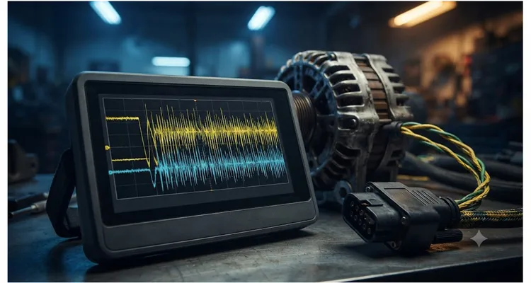
When a J1939 backbone is healthy—a network built on the CAN bus physical layer—a scope shows a textbook differential waveform. CAN_H lifts to about 3.5 volts, CAN_L sinks to 1.5 volts, and the math trace—CAN_H minus CAN_L—paints a clean square wave with a dead-flat recessive baseline. That day in Edmonton, that square wave looked like it had been fed through a wood chipper. The baseline was bouncing in lockstep with the alternator’s rectified ripple, and I knew immediately the noise hadn’t stayed on the power wire; it had trespassed onto the data lines.
What pours out of an alternator’s B+ stud isn’t laboratory-grade DC. It’s rectified three-phase AC, and even a healthy unit leaves a faint sawtooth on the voltage rail. A brand-new 24-volt alternator on that PACCAR idled with about 90 millivolts of ripple showing on the Fluke. The SAE J1939-11 physical layer document draws the line at 0.5 volt peak-to-peak at the network supply pins, and most truck builders tighten that to 0.2 volt internally. So 90 mV was fine. The problem unit read 3.2 volts peak-to-peak. That kind of jump doesn’t come from worn brushes—it comes from a diode that’s gone open, turning three-phase full-wave rectification into a lumpy two-phase mess. Once you see a waveform that looks like a half-hearted sawtooth with one peak missing, you don’t need to memorize the spec; you know the alternator is junk.
That electrical hash doesn’t politely confine itself to the B+ cable. It couples into the CAN lines through ECU power supplies, shared ground paths, and radiated noise if the J1939 backbone runs too close to the alternator cable. The differential transceivers have a common-mode input range. Once the noise exceeds that range, or once the ripple glitches hit the logic threshold, you start getting bit errors. Here’s the sequence we captured on the scope in Edmonton: a spike packet hit the bus at 800 Hz, the differential signal glitched below the receiver threshold, and the aftertreatment module‘s frame—a DM1 message carrying DEF tank temperature—failed its CRC check. The module’s transmit error counter ticked up. A few dozen more glitches pushed it past 255, and the node went bus-off. For 0.8 seconds, the engine ECU heard silence from the aftertreatment controller. That’s all it takes. The ECU assumes a critical emissions sensor has gone offline, torque drops to 60 percent, and the driver feels the truck fall on its face. Then communication snaps back and the event is invisible to a post-trip scan unless you know to look at error counters.
Here’s the part that catches even seasoned technicians off guard: the phantom derate often surfaces when the charging system seems least suspicious—highway cruise, moderate electrical load, alternator spinning fast. The ripple is frequency-dependent—worse at certain RPM bands—so the problem might disappear at idle and only manifest at 1500 to 1800 rpm. This RPM-specific signature isn’t unique to alternator ripple. We’ve already documented intermittent J1939 faults that only appear at 1800 rpm and traced them to multiple physical-layer triggers. When a derate repeatedly hits a narrow RPM window, the charging system belongs high on your suspect list.
A Case in Point: The Ripple That Wiped Out the Aftertreatment J1939 Link
Let me give you the details from that Edmonton job. Truck was a 2020 Kenworth T880 with a PACCAR MX-13, 24-volt system. The fleet had replaced both batteries six months prior after a cold-weather no-start, so they assumed the electrical foundation was solid. The complaint was a silent derate that occurred roughly once every 150 miles, with no consistency in terrain, load, or ambient temperature. I connected a PicoScope to the J1939 bus via a breakout at the 9-pin diagnostic connector, set up a math channel for CAN_H minus CAN_L, and recorded during a road test. Sure enough, when the engine speed hit 1600 rpm under load, the differential signal developed a violent spike packet at about 800 Hz—clearly the alternator’s rectified ripple frequency. Frame errors started piling up. The aftertreatment module’s DM1 message dropped out for 0.8 seconds, the engine ECU logged a timeout on the DEF tank temperature message, and the torque limit snapped to 60 percent. Then it all came back as if nothing happened.
We pulled the alternator and put it on a test bench. The DC regulation was dead-on at 28.4 volts. But with an oscilloscope across the B+ terminal and case ground, the AC ripple measured 3.2 volts peak-to-peak with a ragged waveform that told me one of the six rectifier diodes had gone open, turning the three-phase full-wave bridge into something closer to half-wave on two phases. The remaining diodes were working overtime, but the ripple was astronomical. This alternator was still starting the truck every morning, still keeping the batteries at float, and still passing a quick service-bay voltage test. It was a silent CAN killer.
We installed a new OE alternator, rechecked ripple at the J1939 backbone—at the weather-pack connector near the firewall—and saw a clean 0.15 volt peak-to-peak. Two weeks of hard running later, not a single phantom derate. Total parts cost for the fix: one alternator. Total wasted money by the fleet before this: roughly eleven thousand dollars in misdiagnosed parts and labor.
How to Hunt Down J1939 Power-Ripple Issues Before You Change Another Sensor
If you’re chasing intermittent communication faults and someone is already reaching for a new DPF or an EGR valve, stop. Do this sequence instead. You’ll need a true-RMS multimeter with a peak capture function or, better yet, a two-channel oscilloscope, a J1939 breakout harness (because the scan tool alone will lie to you about the physical layer), and about thirty minutes.
Step 1: Pull the J1939 Error Counter Data Before Anything Else
Use a scan tool that can read SAE J1939 diagnostic codes and look at the network statistics. You want DM1 and the transport layer’s internal counters—specifically “Receive Error Counter” and “Transmit Error Counter.” If you see non-zero values that increment during a road test, you have physical-layer corruption. It’s not an application-layer bug. Write down the source addresses of the controllers logging the errors.
Step 2: Measure Ripple at the Batteries Under Load
Set your multimeter to AC volts, true-RMS, with a min/max/peak function. Place the leads directly on the battery terminals, not the cable clamps. Have someone hold the engine at 1500 rpm with all major electrical loads active (headlights on high beam, blower fan at full, grid heater if applicable). A healthy 12-volt system should show less than 0.1 volt AC, 24-volt system less than 0.25 volt AC. If you’re seeing 0.5 volt or above on 24 volts, suspect excessive alternator ripple. And if your meter doesn’t have a true-RMS AC+DC bandwidth of at least 20 kHz, know that you’re likely under-measuring the noise. I’ve seen standard meters report 0.3 volt while a scope showed 1.8 volts. Know your tool’s limitations.
Step 3: Scope the B+ Terminal on the Alternator
Using an oscilloscope with the ground lead as short as possible, probe the alternator output stud against the case. Set your vertical scale to 1 volt/division AC coupled, time base around 2 to 5 ms/division. Look at the waveform. A healthy alternator will show a gentle sawtooth with a frequency equal to engine RPM multiplied by the number of alternator poles divided by 60, and an amplitude under half a volt. A failed diode shows up as a missing or distorted peak every sixth ripple, with amplitude two to ten times normal. If you see voltage spikes that look like shark fins or dramatic drops to near zero between peaks, you’ve found your culprit.
Step 4: Cross-Check Noise on the J1939 Bus Itself
Leave the engine at the problematic RPM. With your J1939 breakout or a carefully back-probed 3-pin Deutsch connector, scope CAN_H relative to ground and CAN_L relative to ground. Use the math function to subtract CAN_L from CAN_H for the differential signal. Superimpose the alternator ripple waveform. If you see ripple patterns that align with the CAN bit errors and the differential voltage regularly dips near the 0.9-volt recessive threshold due to noise, that’s a confirmed physical-layer corruption from the power supply. If you’re new to capturing CAN differential waveforms, our J1939 oscilloscope waveform diagnostics guide walks through the vertical scale, time base, and math channel setup so you don’t miss the glitch.
Step 5: The Belt-Removal Sanity Check
If you can safely do it, remove the alternator drive belt or disconnect the field circuit, depending on the design, and briefly run the engine on battery power only. If the J1939 error counters stop climbing and the differential signal cleans up instantly, you’ve got a definitive diagnosis. Do not load the batteries heavily during this test; keep it short. This final step has never let me down.
Step 6: Replace or Rebuild the Alternator, Then Validate
After installing the new unit, repeat steps 2 and 3. Reconnect everything, clear the network counters if your scan tool allows, and road test while logging the J1939 error registers. They must stay at zero for the entire drive cycle. No exceptions.
Five Mistakes That Keep This Problem Hidden
- Trusting a DC voltmeter as the only electrical health check. I once watched a shop replace two alternators because their DC voltage reading at the battery showed 28.2 volts—perfect. They didn’t have a scope and never saw the 4-volt AC sawtooth riding on that DC. The third alternator also tested “good” on DC, and the truck kept derating. That’s when they called me. A multimeter set to DC averages out massive ripple and gives you a comforting number that means nothing.
- Replacing ECUs without first proving the physical layer is clean. ECMs, TCUs, and aftertreatment controllers are robust, but they can’t communicate through a noisy power rail. I’ve seen a fleet swap three ECUs on the same truck while the original alternator quietly cooked the replacements, each new unit lasting a few months before communication errors returned. A simple physical layer test can save thousands in misdiagnosis and keep a perfectly good ECM from landing in the scrap bin.
- Adding extra grounding straps or ferrite chokes as a quick fix before locating the source. Ground loops can camouflage the symptom temporarily, but I’ve traced one case where a well-meaning tech added a thick braided ground strap from the alternator bracket to the frame, which created a new ground loop that injected even more noise into the ECM’s reference plane. The J1939 bus was designed to work without add-on filters. Fix the alternator.
- Plugging a CAN “terminator plug” into the diagnostic connector to stabilize the bus. I once saw a tech thread a 120-ohm terminator into the 9-pin because the bus “looked noisy.” It dropped the impedance to roughly 60 ohms, making the CAN transceivers work harder and actually increasing susceptibility to common-mode noise. The phantom derates got worse, not better. The backbone needs exactly two terminations at the farthest nodes, nothing at the diag port.
- Dismissing an alternator because it’s relatively new or a “premium reman.” Many reman alternators get fresh bearings, brushes, and a voltage regulator but reuse rectifier plates with diodes that have borderline reverse-recovery times. At room temperature on a bench they look fine. At 180 degrees underhood, the ringing starts. I always scope the B+ terminal of any replacement alternator before closing the hood—regardless of what the reman label claims.
Proving the Repair Stuck: What a Clean J1939 Bus Looks Like
After the repair, do not hand the keys back without a hard validation. Road test for at least a 45-minute mixed cycle that includes sustained high-rpm operation, full-torque pulls, and a heat soak restart.
Validation Checklist: Four Parameters to Log
Log these four things concurrently:
- Alternator AC ripple at the battery (it must remain below 0.25 volt AC on a 24-volt system).
- J1939 Transmit Error Counter for all source addresses.
- Differential CAN signal peak-to-peak voltage (should be 2.0 volts ±0.5 during dominant bits, flat baseline during recessive).
- A parameter that reflects engine torque output—I typically use “Actual Engine Percent Torque“—to ensure no momentary drops correlate with error events.
If you have a scope that supports mask testing, set up a pass/fail envelope around a known good differential waveform and let it run during the road test. One single excursion outside the mask is a red flag. This is not overkill; it’s the difference between a repair that lasts and a truck that leaves your customer stranded three hundred miles away.
Below is a quick reference for what healthy alternator ripple levels should look like at the battery terminals. Use this table alongside your scope or true-RMS meter to know when to dig deeper.
| System Voltage | Healthy Max Ripple (AC) | Action Threshold |
| 12-volt | < 0.1 V | > 0.1 V – investigate |
| 24-volt | < 0.25 V | 0.25 V – locate source |
| 24-volt (J1939-11 limit) | 0.5 V peak-to-peak max | Approaching margin |
Tools That Let You See the Ripple Without Guesswork
Over the years, I’ve built a box of J1939 breakout adapters and test leads that I trust. The right harness makes the difference between a diagnosis that takes half a day and one that takes twenty minutes. A solid breakout cable with individually shielded twisted pairs and a robust overmold will not add its own noise to the measurement. When you’re looking for 200-millivolt glitches, the last thing you want is a flimsy cable with inconsistent contacts.
Custom J1939 Breakout Cables Built for OE Validation
I source my own test harnesses from a team that builds them for OE validation environments. They once caught a batch of connectors with a 0.2-ohm variance in the ground pin crimp during a 100% continuity and signal-integrity test—the kind of attention that keeps a tiny glitch from becoming a diagnostic red herring. Twenty years of factory experience, ISO 9001 and IATF 16949 certification, climate-controlled floors, and every assembly tested before it ships. That matters. A custom breakout cable built to your exact connector pinout, cable length, and wire gauge means you’re not back-probing with sewing pins in a customer’s engine bay, risking damage and introducing stray capacitance. We once built a 6-meter coiled extension with a right-angle 9-pin for a mining truck where the diag port was tucked behind the cab shield—try finding that on a shelf. Whether you need a flying-lead J1939 diagnostics harness, a heavy-duty extension for road testing, or a fully customized CAN monitor cable for a mixed-fleet application, this is engineering support, not a catalog listing.
If your current diagnostic adapter can’t handle the environment—dirt, vibration, temperature swings—you’re fighting the test equipment as well as the fault. The team I work with builds cables that use RoHS-compliant, full-plastic overmold connectors, UL-rated materials, and can put your logo on the tool if you’re running a fleet service program. No minimum order headaches; they’ll build one-off engineering samples. That kind of direct factory access is hard to find.
Frequently Asked Questions
What’s an acceptable alternator ripple level for a J1939 system?
The J1939-11 committee set 0.5 V peak-to-peak as the ceiling, but I’ve seen CAN errors start at 0.35 V on a 24-volt bus if the wiring runs alongside an unfiltered PWM fan harness. My rule: after 0.25 V AC at the battery, I’m finding the source before it strands the truck. On a 12-volt system, keep it under 0.1 V AC. Aim for the lowest practical number.
Can a failing battery cause similar J1939 phantom derates?
Yes, but through a different door. A battery with high internal resistance can’t dampen alternator ripple, so even a good alternator can look noisy. On a Freightliner Cascadia I diagnosed with a weak cell, the ripple was fine at idle but at 1500 rpm with the grid heater cycling, the battery’s internal resistance let the noise sail right onto the bus. A conductance test caught it in two minutes. Always test the batteries when you’re chasing ripple.
Will a new aftermarket alternator solve ripple problems reliably?
Not always. Some aftermarket units meet the DC voltage spec but use rectifier diodes with slower reverse-recovery characteristics that generate higher-frequency ringing. I strongly recommend testing any replacement alternator on a bench scope before installing it. A rebuilder who uses new OEM-specification diodes and tests for ripple is worth the extra cost.
How can I check for alternator ripple without an oscilloscope?
A quality true-RMS multimeter with a peak capture function and adequate AC bandwidth can give you a first-pass indication. Set it to AC volts, connect directly to the alternator output, and rev the engine. If you read more than 0.5 volt AC on a 24-volt system, investigate further. Just know that meters without true-RMS can under-report the noise by 40% or more—I’ve watched a standard meter display 0.3 volt while the scope showed a very real 1.8 volts.
Why does the derate happen only at certain engine RPM?
The alternator ripple frequency changes with engine speed. On that Kenworth in Edmonton, the derate appeared at 1600 rpm because the 800 Hz ripple harmonized with the 250 kbps CAN bit timing just enough to flip a bit every few frames. At 1400 rpm, the frequency shifted and the bus stayed quiet. This is the same RPM-specific pattern we unpacked in our intermittent J1939 faults at 1800 RPM case study. Some alternator brackets also transmit vibration that affects brush contact pressure at specific RPM ranges, introducing sporadic noise.
Is it possible to filter the noise out of the CAN bus without replacing the alternator?
You can sometimes mask the issue in an emergency with common-mode chokes or power-line filters, but it’s temporary camouflage. J1939 systems are designed to operate without extra filtering. Adding passive components changes the bus impedance and can create hard-to-diagnose edge-case failures. I once saw a filter introduce a ground offset that caused its own intermittent CAN errors. Always fix the source.
Can an alternator ripple problem damage my ECUs permanently?
Prolonged exposure to excessive ripple stresses the input capacitors and voltage regulators inside ECUs, potentially shortening their lifespan. I’ve seen multiple ECU failures in the same vehicle traced back to a rectifier fault that went undetected for months. It’s a slow corrosive effect, not an immediate blowout.
What’s the connection between alternator noise and aftertreatment faults?
Aftertreatment controllers often sit at the far end of the J1939 backbone, electrically distant from the main power distribution. On that T880, the aftertreatment module was the last node. Every time the bus dropped out, the engine ECU saw a missing DEF tank temperature message and initiated a derate. The aftertreatment system is frequently the first indicator of trouble on a noisy J1939 bus.
Do electric cooling fans and other high-current loads contribute to this issue?
Absolutely. PWM-controlled electric fans can generate their own conducted noise. On one truck I worked on, the derate only appeared when the engine fan kicked into high speed; the fan’s PWM circuit and the alternator ripple combined to create a 1.2-volt spike on the CAN lines. When you’re diagnosing a phantom derate, activate every high-current accessory during the ripple test to see the worst-case scenario.
How often should I proactively test for alternator ripple?
I start seeing rectifier diode wear around 250,000 to 350,000 miles on vocational trucks that log a lot of idle time with high electrical load. After 300,000 miles, I check ripple at every PM. The test takes two minutes with a multimeter, and I’ve caught three failing alternators this year before they caused a road call.
If Your J1939 Problem Doesn’t Make Sense, Start at the Power Source
A decade of chasing intermittent CAN faults has taught me that the physical layer holds the answers the diagnostic trouble codes won’t give you. The next time you have a truck that derates without leaving a clear trail, don’t open the parts catalog. Put a scope on the alternator, watch the error counters, and listen to what the electrons are telling you. The ROI of basic physical layer tools is immediate—they slash diagnostic downtime and shut down the parts cannon for good.
The diagnostic harness you use to connect your tools matters more than you think. If you need a J1939 breakout cable that won’t add its own noise to the measurement—or if you’re building a fleet diagnostic kit and need custom pinouts, branding, or specific AWG and jacket material—reach out directly. We manufacture at scale with a factory mindset: ISO 9001, ISO 14001, IATF 16949, REACH, RoHS, and UL compliance are part of the daily routine, not marketing bullet points. Every cable that leaves the floor has passed a four-step quality inspection under 5S management, down to the crimp force on each terminal.
Have a specific engineering question, or need a one-off prototype to solve a tough communication problem on a mixed-fleet platform? You can send me a message on WhatsApp or use the contact form on our site. I respond personally to technical inquiries. Let’s sort out the noise—literally.
WhatsApp: Chat with Linda now at https://api.whatsapp.com/send/?phone=8617307168662&text=Need+Help%3F+Chat+linda+WhatsAPP&type=phone_number&app_absent=0
Contact Page: Submit your project details at https://obd-cable.com/contact/
No forms to trap you, no automated chatbots. Just a factory engineering team that understands why the physical layer keeps the whole truck talking.
