

The protocol rarely fails. The copper underneath it does. I paid for that lesson eighteen years ago, standing beside a fuel tanker that cranked but wouldn’t fire because the instrument cluster lost communication with the transmission ECU. The diagnostic scan tool reported an “abnormal update rate” on J1939. The workshop had already replaced the cluster, the engine harness, and the entire ABS module. Eight thousand two hundred dollars in parts, six days of downtime. Not one technician had put a voltmeter on CAN_H.
That week I soldered together the first version of what I now reach for on every call: a J1939 breakout kit that cost under one hundred forty dollars in components. In a mixed fleet, it paid for itself not in months—inside the first three service calls. Here’s why it works, how to build it properly, and where most people completely misread the physical layer.
Aging Harnesses, Mixed Fleets, and the Missing 120 Ohms
Any mixed fleet is a rolling collection of electrical compromises—a museum where every added sensor, spliced stub, and twisted-on telematics gateway tells the story of a shortcut. You have a 2015 truck with a factory-terminated J1939 backbone, a 2008 trailer with a field-spliced stub, and a freshly installed telematics box someone connected by twisting wires and calling it “temporary.” The J1939 data link is a single twisted pair that every module treats as a shared party line. When that line degrades—intermittent shorts, missing termination, shield current loops—the SAE J1939 protocol has no mechanism to report where the physics failed. I have seen poor termination and stub length design create phantom faults that cost fleets thousands annually, with zero traceable fault codes to point the way. It simply logs “timeout.”
The worst case I witnessed wasn’t random parts swapping. It was a complete diagnostic logic chain snapping. A mining fleet replaced all six injector harnesses because the fault code read “injector circuit malfunction.” The real cause? A corroded ABS module pulling CAN_H down by zero-point-eight volts—a textbook common-mode voltage shift that kills J1939 communication—hovering right at the threshold where messages still tried to pass but ECUs dropped frames. The takeaway: a J1939 fault code is a witness at a crime scene. It names the victim, never the perpetrator.
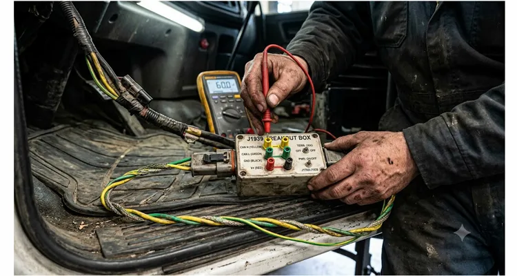
A purpose-built J1939 breakout kit changes your entire diagnostic approach. It gives you real-time electrical access to every pin on the 9-pin Deutsch connector without interrupting the network. You can simultaneously monitor voltages, measure termination resistance, observe idle bus traffic, inject a scope probe, and isolate individual nodes—all while the engine torques, the frame twists, and the machine works.
Building a Production-Ready J1939 Breakout Kit
This is not a bench-top toy. A breakout box that survives a diesel shop floor needs rugged Deutsch connectors, over-spec wiring, and thoughtful protection against the day a technician accidentally clips 24V battery power onto a test point. Here is the build I have refined across several hundred field hours.
What You Need
The bill of materials is short. But every component on it earned its place through a failure I would rather not repeat.
Begin with the connectors, because everything downstream—signal integrity, water ingress, even your ability to unplug the kit one-handed—depends on them. You need a male 9-pin Deutsch (HD16-9-1939PE) to mate with the vehicle-side diagnostic connector, and a female 9-pin Deutsch (HD10-9-1939PE) for the scan tool or pass-through. Do not substitute generic circular connectors; genuine Deutsch IP67 sealing is what keeps mud and salt spray out of your measurement path. The enclosure can be die-cast aluminum or heavy ABS, roughly one hundred thirty by eighty by fifty millimeters, large enough to hold nine banana jacks and two toggle switches without crowding. I prefer ABS because it will not scratch a painted cab door if the pigtail swings.
For the banana jacks, use nine panel-mount 4mm sockets, color-coded by function: black for ground, red for battery positive, yellow for CAN_H, green for CAN_L, and bare-metal or brown for the shield drain. The color coding is not cosmetic—it stops a tired technician from accidentally clipping a scope probe onto 24V when they meant to hit CAN_H. I learned that lesson watching someone else’s mistake.
Two SPDT toggle switches, rated for at least 30V DC, control selectable 120Ω termination resistors on the J1939 bus. Use quarter-watt metal film resistors with one percent tolerance. One resistor switches across CAN_H to CAN_L, the second across J1708 Data+ to Data–. Why include J1708 termination? Because mixed fleets still operate plenty of J1587 on pre-2010 equipment, and chasing a fault on the secondary bus without correct termination wastes an afternoon.
The LED Circuit: Optional, But Built From Frustration
I added LED indicators purely out of frustration with reading a multimeter display while lying on my back under a chassis in poor light. The common DIY mistake is wiring a bare LED with a 1kΩ resistor directly from CAN_H to ground. That can sink enough current to distort the CAN differential signal on a weak network, and you end up diagnosing a problem you created yourself. My preferred circuit uses a rail-to-rail op-amp buffer to drive high-brightness LEDs without loading the bus. If that feels over your head, a simpler version with 10kΩ series resistors and super-bright LEDs works acceptably—provided you add a switch to disconnect the indicator circuit when taking precise scope measurements.
For internal wiring, use 20AWG cross-linked polyethylene or GXL insulation, striped and labeled. Cross-linked insulation shrugs off heat and diesel without becoming brittle after two summers. Include a cable gland (PG9 or M12) for strain relief on the pigtail harness. The breakout harness itself should be a 14-conductor twisted-pair cable with an overall shield—enough conductors for all nine pins plus spares. You will use them eventually.
If building from scratch isn’t practical for your timeline, a pre-assembled J1939 9-pin pigtail breakout cable can serve as the foundation—just add your enclosure, banana jacks, and termination switches to complete the kit.
Pinout: Making Sense of the 9-Pin Deutsch Diagnostic Connector
Below is the mapping I trust. The pin assignments are industry standard, but the breakout decisions come from field failures.
Pin A carries ground. I connect it to a black banana jack bonded to the enclosure ground. Simple, but always ohm out that connection before trusting it—a floating ground inside your breakout box will send you in diagnostic circles.
Pin B is unswitched battery positive. It gets a red banana jack with an internal 1A fast-blow fuse placed right at the connector. A dead short inside the box must never take down the vehicle. I have seen that happen, and the tow bill alone surpassed the cost of this entire diagnostic kit.
Pins C and D are CAN_H and CAN_L, yellow and green respectively. You will probe these two ninety percent of the time. Label them clearly and double-verify your wire routing—crossing CAN_H and CAN_L inside the box inverts every differential frame.
Pin E is the shield drain. Here is where most techs go wrong. They bond it as a second chassis ground. What you actually want is AC coupling to the case through a 1µF capacitor, if anything at all. I label this jack “Shield,” not “GND,” because I want the technician to pause before connecting it. The J1939 shield is designed to carry noise, not current.
Pins F and G carry the J1708 data link. I keep these broken out on white/blue and white jacks because vocational trucks continue to route auxiliary data through J1587 even on modern chassis. It costs almost nothing to include and prevents a return visit.
Pins H and J are OEM reserved. I wire them to spare jacks, clearly labeled. You never know when a body builder has taken over one of these for a PTO signal or a dump body interlock.
Assembly Logic
Build the kit as an in-line pass-through device: wire the male and female Deutsch connectors pin-to-pin, then tap each circuit to a dedicated banana jack. This way the J1939 network stays intact while you probe. The termination switches place a 120Ω resistor directly between CAN_H and CAN_L—and a second between J1708+ and J1708–—so you can add or remove termination on the fly. This matters more than it sounds. I have found missing terminating resistors on trucks that ran for three years because the bias voltage was just strong enough to limp along.
The whole assembly needs potting or serious mechanical strain relief. When a twenty-five-foot pigtail gets yanked by a forklift—and it will—the internal solder joints and terminations must hold. Our factory uses a full-plastic overmold design that seals against salt spray and diesel, but for a DIY build, a well-anchored cable gland plus internal zip-tie strain relief anchors do the job. For tight engine bays where a straight connector won’t fit, a J1939 90-degree right-angle cable can keep the breakout kit accessible without straining the harness.
How the Breakout Kit Pays for Itself in Ninety Days: A Real Fleet Case
An aggregate hauler I work with operates a mixed fleet of twelve on-road trucks and six off-highway articulated dumpers. Three OEM brands, four engine tiers, CAN buses spliced into weigh scales and onboard printers. They were experiencing random J1939 communication faults that locked the transmission in first gear—a derate that halted production. Over six weeks, two transmission ECUs and one engine harness were replaced, at a total parts cost of nine thousand three hundred dollars. The fault never stayed fixed.
With the breakout kit inserted in-line, we hot-plugged a PicoScope on pins C and D and caught something the scan tool never reported: the CAN_H voltage intermittently collapsed to one-point-one volts for two hundred milliseconds, exactly when the bed tilt sensor transmitted a frame. The CAN frame was getting through just enough to wake the sensor but not enough for the transmission to remain synchronized. The culprit turned out to be a corroded inline Deutsch connector hidden under the cab floor, which had developed high resistance on the CAN_H leg—but only when moisture bridged the seal at certain tilt angles. One fifteen-dollar Deutsch connector and ninety minutes of crimping later, the fault disappeared permanently.
Build cost of the kit: about one hundred thirty dollars. That single diagnosis saved the fleet from replacing a third transmission ECU—roughly three thousand two hundred dollars—plus a full day of downtime. Over the next ninety days, the same J1939 breakout tool was used on four additional intermittent network faults across the fleet. Total avoided parts cost exceeded fourteen thousand dollars. The break-even point arrived in under two weeks.
Common Mistakes That Turn a Good Breakout Box Into a Diagnostic Trap
Even with a properly built J1939 test kit, certain mistakes repeat across workshops. I have made most of them myself at least once.
Bonding the J1939 shield as a chassis ground remains the number-one wiring error I see. The shield drain on Pin E is designed to be AC-coupled to chassis at exactly one point. Hard-grounding it inside the breakout box creates ground loops—a problem we’ve documented where a 0.3V ground offset cost a fleet nine thousand eight hundred dollars—that corrupt CAN traffic and lead you to blame a perfectly healthy module for the noise.
Measuring termination resistance with the ignition still on is another common trap. A 60Ω reading between CAN_H and CAN_L with the bus fully asleep confirms correct dual-termination for J1939. If a module is partially awake, you may read anywhere from fifty-five to seventy ohms and chase a phantom issue for hours. Always measure key-off, after a thirty-second power-down, and verify the reading is rock steady. Keep in mind that even a correct 60Ω reading at the diagnostic connector does not rule out termination and stub length problems deeper in the backbone—a lesson I learned the hard way on a truck that passed every static test but fell off the bus under load.
Forgetting the J1708 bus is an expensive oversight. Many 9-pin breakouts expose only CAN. On a mixed fleet with older body controllers or hydraulic valve modules communicating over J1708, you miss the secondary bus entirely and release a truck you believe you have fixed—that still refuses to move.
Using an OBD-II passive breakout box with a Deutsch adapter is something I have watched go up in smoke, literally. Heavy-duty equipment often runs on 24V systems. An OBD-II breakout box routes battery voltage directly on pin sixteen, and its internal protection rarely survives 24V continuous. The ground pin assignments also differ—the OBD-II chassis ground is not where a Deutsch 9-pin expects it.
Skipping the LED buffer on active indicator circuits rounds out the list. A bare LED with a low-value resistor hung across CAN_H to ground can sink enough current to distort the CAN differential signal on a marginal network. Either buffer the circuit properly or provide a dedicated switch to disconnect the indicator when you are capturing precise scope traces.
Confirming the Repair: How to Know the Fault Is Truly Gone
After any repair, I run a four-step J1939 bus validation using the breakout kit before signing off on the vehicle. This is the quality gate that prevents a callback.
First, resistance at the diagnostic connector. Key off, measure CAN_H to CAN_L. You should read 60Ω ± 2Ω. Measure each pin to ground and to battery; expect an open circuit on every pin except pin A to chassis. Any other reading points to a short, a missing terminating resistor, or a module that has not yet powered down.
Second, voltage check at idle. Key on, engine off. CAN_H should sit between two-point-five and three-point-five volts relative to ground, CAN_L between one-point-five and two-point-five volts. The recessive differential voltage should be roughly one to two volts. Anything outside that window suggests a driver fault or a bias issue inside one of the networked ECUs.
Third, live traffic observation. With a scope or the buffered LED activity monitor, confirm that CAN frames appear when the ignition is cycled and when the suspect loads actuate. The waveform must look clean and periodic, not intermittent or stair-stepped.
Fourth, the physical stress test. Wiggle every accessible harness segment while watching the scope trace. Intermittent faults live inside connectors and splices, not inside potted ECUs. This is essentially a structured wiggle test protocol for J1939 harness opens. If the waveform remains stable through the wiggle test, you have almost certainly found and corrected the root cause.
When the bus passes all four checks and the active J1939 fault codes clear without returning, the loop is closed. Release the vehicle and log exactly what you found—pattern data across multiple assets is what convinces a fleet manager to fund systemic wiring repairs.
When a Homemade Kit Isn’t Enough: Scaling to Fleet-Wide Deployment
The kit described above will solve the majority of physical-layer diagnostic challenges for a single technician. But when a fleet of forty or four hundred assets needs identical tools—with controlled build records, consistent training color schemes, and the durability to survive a rollaway toolbox falling onto concrete—a bag of parts and a Saturday at the workbench do not scale.
The problem shifts from “can I build one good diagnostic breakout box?” to “will the hundredth unit be identical to the first, and will my safety department sign off on a tool that lacks controlled tooling and documented test data?”
That is where direct factory engineering support changes the calculation. We do not hand you a stock SKU and walk away. We provide an alternative to managing build consistency inside your own maintenance work-order system. Our production line traces every crimp die and wire spool by batch, so if your team discovers a marginal contact resistance trend on certain Deutsch connectors at specific frequencies, we can trace backward to the exact tooling and material lot. The process runs under IATF 16949, a certification milestone we’ve detailed in our automotive quality excellence achievement, which means failure mode and effects analysis is engineered in before the first assembly—not inspected in afterward. That discipline matters when the tool is expected to deliver trustworthy measurements for years.
OEM customization is a standard workflow, not a special project: your company logo, cable length, AWG, jacket color, and connector brand can all be specified without a separate engineering charge. A frequent request is a two-tone overmold—yellow for the CAN side and grey for J1708—so field techs orient the connector correctly in poor lighting or while wearing heavy gloves. The full-plastic overmold design resists diesel, hydraulic fluid, and UV exposure, and every single assembly is 100% continuity-tested before leaving the floor. The climate-controlled warehouse operates under 5S management because consistency in storage translates directly to consistency in the finished diagnostic cable assembly.
The objective is not to sell you a box. It is to offer a fleet diagnostic tool that arrives with a build data sheet, allowing your maintenance department to enter it into the calibrated equipment log and your safety officer to approve it without hesitation. The factory builds to your specification, not to a catalog part number.
What exactly does a J1939 breakout kit do that my scan tool cannot?
A scan tool decodes parameter groups and J1939 fault codes at the application layer, showing you what the ECUs are reporting. A J1939 breakout kit gives you direct electrical access to the physical bus: you can measure CAN voltages, termination resistance, and waveform anomalies, and you can splice a scope or data logger into the live network—all without back-probing fragile Deutsch seals. It lets you see the wires and the signals, not just the translated messages.
Can I use this kit with 24V construction equipment?
Yes. The design is voltage-agnostic as long as every component is rated for at least 32V DC. That includes any LED buffer circuit, the termination resistors, and the wiring insulation. Always check the voltage rating of any active buffer you add. The B+ line fuse protects the vehicle regardless.
Is it safe to build without an electronics background?
A basic passive version—switches, resistors, banana jacks, and point-to-point wiring—can be assembled by any competent technician who can crimp Deutsch terminals and follow a simple schematic. Adding active LED indicators requires elementary op-amp design. If that falls outside your comfort zone, stay passive. The diagnostic value of a purely passive J1939 breakout box remains immense.
How does the kit help with intermittent faults specifically?
Because the kit sits in-line, you can connect a multimeter or oscilloscope and leave it connected while the vehicle operates—driving over bumps, articulating, reaching full operating temperature. You are watching the CAN bus while the fault occurs, which is the only reliable method to catch a vibration- or temperature-sensitive weak point. Intermittent J1939 faults that take weeks to reproduce on a bench often reveal themselves within the first hour of live monitoring.
Do I need to monitor J1708 if my entire fleet is newer than 2015?
Not necessarily. However, many vocational trucks and engine retrofit packages continue to route auxiliary data through J1708 or J1587 even on late-model chassis. I keep it broken out because it costs almost nothing to include and prevents a return visit when you discover the body controller you forgot about communicates exclusively over J1708.
What is the single most helpful measurement to take with this kit?
CAN_H to CAN_L resistance with the ignition off and the bus fully asleep. In a correctly terminated J1939 network, a 60Ω reading confirms that both 120Ω terminating resistors are present and the backbone is intact. An open circuit or 120Ω instantly narrows the fault to an open backbone or a missing terminating resistor—two of the most common J1939 failures that a scan tool cannot directly report.
How do I protect the kit from accidental 24V battery shorts on the bench?
Fuse the B+ line internally at the connector with a fast-blow 1A fuse. Keep exposed metal banana jacks covered with insulating boots when not in use. Some builders prefer PTC resettable fuses; I use a glass fuse because it is easier to visually confirm a blown condition and replace in the field without opening the enclosure.
Can you supply a custom-built version with our company name and specifications?
Yes. Our engineering team handles OEM customizations including logo, cable length, connector color, AWG, and specific labeling. We can also package the J1939 breakout kit in a branded case with your work instructions printed inside the lid. This is a standard request from mining fleets and equipment rental companies that need identical diagnostic tools across multiple job sites.
What certifications do the factory assemblies hold?
The facility operates under ISO 9001, ISO 14001, and IATF 16949 quality management systems. Products meet RoHS and REACH compliance, with UL-listed components where specified. The assembly line follows a four-step quality inspection and performs 100% electrical testing in a climate-controlled, 5S-managed environment.
What’s the first step if I’m interested in an engineered kit for my fleet?
The most productive first step is an engineering conversation—no commitment, no pricing pressure. Tell us your fleet mix, preferred connector brand, and any technician training constraints. We can prepare a one-page proposal drawing so your team can review the electrical and mechanical approach and confirm it fits your diagnostic workflow before any production begins.
Where a Simple Box Leads
This breakout box will not turn you into a master diagnostician overnight. But it removes the single largest blind spot in modern commercial vehicle troubleshooting: the physical layer you cannot see through a scan tool. I have watched technicians go from desperately swapping a third ECU to calmly identifying a corroded pin inside a junction block—within the same afternoon—simply because they could finally watch what was happening on the copper.
If you are staring down a fleet that mixes three generations of CAN and pre-CAN hardware, build one of these J1939 diagnostic breakout kits. It will cost you less than a single misdiagnosed actuator. And if you need that same capability replicated across every shop, with uniform build quality and your own logo on the faceplate, our engineering team has been building heavy-duty diagnostic cable assemblies long enough to understand that the best tool is the one your technicians actually trust enough to plug in on every call.
For OEM customization, engineering drawings, or a second set of eyes on a persistent fleet network fault, reach out directly:
- WhatsApp: Chat with Linda
- Contact Page: obd-cable.com/contact/
No pricing scripts, no stock part numbers pushed at you. Just a discussion between engineers who have seen enough burned pins and intermittent J1939 faults to know exactly what a trustworthy breakout kit should do.
