

The machine passed every acceptance test. Three hundred hours of runtime without a single error frame. Then it shipped to a customer in northern Alberta, and within forty-eight hours, the J1939 bus was dead. We flew the entire J1939 harness back to the lab. Every wire rang out perfect on the continuity tester. Every termination resistor measured within one percent of spec. It took us four days to realize the problem wasn’t in the CAN bus harness at all. It was in a four-inch ground strap we’d installed exactly where the installation drawing told us to.
That ground strap, a perfectly innocent-looking braided copper link between the engine block and the chassis rail, was carrying the return current from a twenty-five-amp hydraulic pump solenoid. At the solenoid’s switching frequency—somewhere around four hundred Hertz—that strap had enough inductance to develop a one-point-eight-volt drop across its length. The engine ECU, grounded to the block, saw its local reference sitting at zero. The transmission controller, grounded to the chassis four feet away, saw its local reference bouncing up and down by nearly two volts at every PWM cycle. The J1939 network, strung between them, was being physically yanked out of its common-mode range four hundred times a second. The differential signal never stood a chance.
I didn’t figure this out by being clever. I figured it out after four days of being wrong. And that’s the thing about common-mode voltage faults on J1939 that nobody tells you upfront: they’re almost never caused by the CAN bus itself. They’re caused by the electrical architecture surrounding it. The bus is the victim, not the perpetrator.
When the J1939 Bus Falls Silent at Exactly the Wrong Moment
There is a specific fingerprint to a common-mode fault that distinguishes it from every other J1939 communication failure. Once you learn to recognize it, you’ll stop swapping ECUs and start studying the electrical environment the bus lives in.
The primary signature is load-dependent silence. The machine powers up clean. All nodes announce themselves on the bus. Parameter groups flow normally. Then the operator engages one specific high-current circuit—a hydraulic pilot solenoid, a grid heater, a cooling fan clutch—and the entire J1939 network stops. Not degrades. Stops. No intermittent error frames, no gradual increase in bus errors. Just a hard, instantaneous cutoff. De-energize that circuit, and the bus returns as if nothing happened. Every single time.
I’ve watched a transmission controller blame an engine speed sensor that was reporting perfectly, while the instrument cluster simultaneously flagged a data link fault for the aftertreatment system—a module that wasn’t even powered on that machine variant. The fault code list looked like a random number generator. That kind of chaos has a specific signature. It means the CAN receivers aren’t making independent decisions about bit states anymore. They’re being collectively dragged across their threshold voltages by something external to the data link.
This is the point where many technicians fall into a trap: they assume the fault codes are pointing toward a real component failure and start replacing hardware. I’ve seen fleets burn tens of thousands of dollars chasing intermittent J1939 faults with a wiggle test when the root cause was a ground architecture problem that never threw a code of its own.
The Audible Clue Most Technicians Miss
There is a field observation that gets overlooked in every textbook treatment of this problem. If you run a bus analyzer with an audible traffic indicator—some of the older Dearborn Group adapters had this, and I still keep one around for exactly this reason—you can hear the bus die before you ever see it on a scope. Healthy J1939 traffic has a rhythmic, almost musical chatter. Under a common-mode assault, that chatter either vanishes into a dead quiet or morphs into a continuous, high-pitched squeal that corresponds to the bus being driven into a permanent dominant state. Your ears will sometimes find the fault before your eyes do.
The Physics of Common-Mode Voltage Nobody Walks You Through
The textbook explanation of differential signaling goes like this: CAN uses a twisted pair. Receivers are differential amplifiers. They reject common-mode noise because they only care about the voltage difference between CAN High and CAN Low, not the absolute voltage on either line. A noise spike that lifts both lines by the same amount is invisible to the receiver.
All of that is true. It’s also incomplete in a way that will burn you badly if you don’t understand the boundary conditions.
Here’s the thing about differential signaling that bites you when you least expect it. The rejection of common-mode voltage is not a binary property. It’s a spec with a curve. Every CAN transceiver datasheet includes a plot of common-mode rejection ratio (CMRR) versus frequency, and that curve rolls off. At DC, sure, your typical transceiver delivers forty to fifty decibels of rejection—a factor of one hundred to three hundred times attenuation. The two-and-a-half-volt recessive bias can get shoved around by nearly a volt without corrupting a single bit. But the noise that murders a J1939 bus is seldom a clean DC offset. It’s the ragged, sawtooth edge of a pulse-width-modulated solenoid driver, a waveform dense with harmonics stretching from a few kilohertz up into the low megahertz. Up there, at the tenth or twentieth harmonic of a four hundred Hertz switching frequency, that same transceiver’s rejection might have collapsed to a miserable fifteen decibels. Your receiver, which you trusted to ignore the common-mode, is suddenly very much listening to it.
This frequency-dependent degradation of noise rejection is well documented in the broader field of electromagnetic compatibility engineering, where conducted emissions and susceptibility thresholds are defined across the full frequency spectrum—not just at DC.
How Starter Motor Current Destroys Your Ground Reference
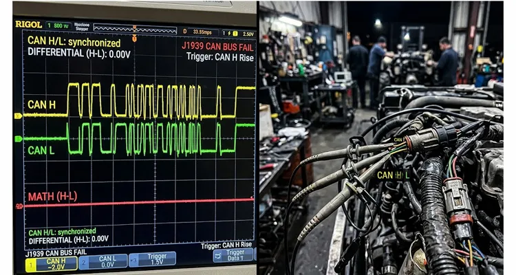
Now add the physical reality of a machine’s ground architecture. The starter motor on a large diesel doesn’t just draw current. It pulls a three hundred and fifty amp punch through the engine block, back through the ground straps, to the battery negative terminal. That block is the ground reference for the engine ECU. The exhaust aftertreatment controller, meanwhile, is bolted to the chassis rail four feet away. Even with braided copper straps at every connection, that high-current pulse creates a transient potential difference between the block and the rail. If just one volt of difference develops—and I’ve measured far worse on machines with corroded ground strap fasteners—the entire J1939 signal, which was sitting comfortably at two and a half volts relative to the engine ECU, is now riding at three and a half volts relative to the aftertreatment controller’s local ground. Add the inductive flyback from a de-energizing solenoid, and you can shove the bus completely outside the transceiver’s specified common-mode input range, which for most five-volt parts runs from about negative two volts to positive seven volts. The receiver’s input stage saturates. Bit recognition ceases. The controller throws a bus-off error and isolates itself. The network fragments, and you are standing in a cold shop with a machine that refuses to communicate, staring at a scope trace that shows two perfectly formed CAN waveforms moving in terrifying, lockstep unison.
This is why I always teach technicians to diagnose J1939 ground offset voltage before condemning any controller. A ground offset as small as 0.3V on a J1939 backbone can consume half your noise margin before a single load switches on.If you are working with a multimeter rather than a scope, the step-by-step J1939 ground offset diagnostic procedure walks through the same methodology using basic shop tools.
How I Track a Common-Mode Fault When It Shows Up: A 4-Step J1939 Troubleshooting Sequence
I’ve developed a sequence for hunting common-mode problems that doesn’t rely on luck or swapping parts until the symptom disappears. This approach has been refined over far too many late nights in prototype bays and on customer sites where the machine absolutely had to run the next morning.
Step 1: Scope the Differential Signal at the Terminator
Begin at the terminator. This is non-negotiable. Connect channel one of your oscilloscope to CAN High, channel two to CAN Low, DC-coupled on both channels. Set the math function to subtract channel two from channel one. With the bus idle and all nodes powered, you should see a clean, nearly flat differential trace with brief, sharp dips corresponding to dominant bits. Now set your scope to display both channels individually, superimposed on the same grid, and configure a single-shot trigger that captures the moment the offending load switches on. You are hunting for a vertical displacement that affects both channels identically while the differential math trace collapses toward zero. That synchronous vertical jump on both CAN High and CAN Low—with no change in the differential signal—is confirmation that the common-mode voltage is being displaced, not the data itself.
If you’re new to capturing these waveforms, I’ve written a detailed walkthrough on J1939 common-mode voltage shift measurement using an oscilloscope that covers probe setup, trigger configuration, and how to avoid the ground-loop mistake that contaminates half the scope traces I see from the field.
Step 2: Find the Common-Mode Current Path (It’s Not Where You Think)
With the phenomenon confirmed, the real work starts. Isolate the node that is acting as a bridge for ground current, not necessarily the node that is generating the noise. This distinction matters. If the bus dies when the hydraulic pump solenoid energizes, do not start by disconnecting the pump controller. Start with the ECUs that share a ground path or a mounting bracket with the pump’s circuit. I once traced a recurring bus failure to a transmission controller whose mounting bolts had been replaced with stainless steel fasteners—lower conductivity than the original zinc-plated parts—creating a high-resistance ground path through the case. The controller wasn’t the source of the noise, but it was the bridge that allowed pump current to modulate the bus reference voltage. A sensor with its shield shorted to chassis at the connector body, a module with an internal ground pin that has fretted to high resistance, or a bracket that was powder-coated before assembly rather than after, leaving an insulating layer between the ECU case and the chassis—any of these can be the bridge.
This is the same mechanism behind what I call the J1939 ground offset misdiagnosis trap: a perfectly functional ECU gets condemned because it sits at the wrong end of a ground differential it didn’t create.
Step 3: Probe the Shield and Ground Wiring According to SAE J1939-11
Next, interrogate the shield. J1939 backbone cable includes a shield that, per SAE J1939-11, must be terminated to ground at exactly one point. In the field, I’ve documented shields connected to ground at both ends, at three ends, at zero ends, and—on one memorable occasion—shields that had been spliced into a ring terminal and bolted to a plastic air cleaner housing, grounding exactly nothing. Disconnect battery power. Use a milliohm meter to measure from the shield drain wire at one end of the backbone to the chassis reference point. A correctly single-point-grounded shield will read a low, stable resistance—typically well under one ohm. An open reading means the shield is floating and providing no protection whatsoever. If, with the system powered and the offending load cycling, you can measure an AC voltage between the shield and chassis, you have found an unintended return current path. The shield has become a conductor for the very noise it was meant to block. Fix the shield termination first, before you touch anything else.
On forestry machines specifically, I’ve documented J1939 harness failures where shield damage during field repairs created exactly this kind of unintended current path. The operator wrapped the damaged section with electrical tape and sent the machine back out. The bus worked for three days, then died the moment the hydraulic grapple hit a heavy log. Water ingress had turned the tape wrap into a high-impedance path to the chassis, and the shield was now grounded at two points with completely unpredictable impedance between them.
Step 4: Verify the Split Termination Bias Network
The final checkpoint in my sequence is the split termination bias network. At each end of a properly designed J1939 backbone, the termination consists not of a single one hundred and twenty ohm resistor but of two sixty-ohm resistors in series, with a capacitor—typically four-point-seven or ten nanofarads—connected from their center node to ground. That termination capacitor is not optional. It provides a low-impedance AC path to ground for common-mode noise, effectively shorting high-frequency junk to the reference plane before it can accumulate on the bus. After years of thermal cycling and vibration, these capacitors can develop micro-cracks in their solder joints or internal electrode connections. They fail open while looking perfectly normal to visual inspection. Without that AC path, the recessive bias voltage floats freely, turning the bus into an antenna exquisitely sensitive to every stray electric and magnetic field in the engine compartment. A capacitance meter applied across that capacitor—with the system powered down—will tell you in seconds whether it is still functioning or has gone open circuit.
This is closely related to a phenomenon I’ve covered in depth: J1939 termination resistance drift between hot and cold states. A bus that measures a clean sixty ohms on a cold bench can drift far enough during a loaded regen cycle to push marginal transceivers over the edge.
Here is a quick-reference summary of the 4-step process:
- Step 1: Scope CAN High and CAN Low simultaneously at the terminator; look for a synchronous vertical jump on both channels while the differential math trace collapses
- Step 2: Isolate the bridge node—disconnect ECUs sharing a ground path or mounting bracket with the offending circuit, not the noise source itself
- Step 3: Measure shield drain wire resistance to chassis with a milliohm meter; confirm single-point grounding per SAE J1939-11
- Step 4: Verify the split termination capacitor is functional using a capacitance meter; an open capacitor leaves the recessive bias floating
Lessons I Paid For So You Don’t Have To: 5 J1939 Common-Mode Mistakes
Some of these I learned from textbooks. Most I learned from failures that cost real time, real money, and real credibility. I offer them here in the hope that they prevent someone else from staring at a dead machine at 2 AM, wondering what they’re missing.
Mistake 1: The “Battery Negative” Trap
A technician adds a telematics module to an existing machine. Ignition power is convenient at a cab switch, but ground is inconvenient to run all the way back to the battery. The engine block is right there, with an unused threaded boss. They bolt the ground wire to it. What they have just done is connect their new module’s CAN transceiver across a potential difference highway. When the alternator is charging and currents are flowing through the block to the chassis, that module’s local ground reference can be offset from the rest of the bus by hundreds of millivolts—more than enough to consume a significant fraction of the available common-mode margin. Every J1939 node should derive its power and ground from the same physical reference point as the rest of the bus, or it should be isolated through a dedicated DC-to-DC converter.
I’ve watched entire fleets develop network reliability problems after aftermarket telematics installations that all traced back to this single wiring shortcut. The telematics units themselves were fine. The ground point selection was the silent saboteur.
Mistake 2: Shield Grounding at Every Drop Point
I once signed off on a harness design that grounded the J1939 shield at every single drop point—five locations along the backbone. It looked defensive on the schematic. I thought I was being thorough, creating multiple paths for noise to drain away from the data lines. That machine developed a two-volt common-mode oscillation at exactly the PWM frequency of the hydraulic pump, and we chased the root cause for six weeks. What I had accidentally designed was a five-turn transformer winding, with the chassis as the magnetic core. Current circulating in the shield loop was inducing the very interference I was trying to eliminate. I have since learned to state the rule without ambiguity: a shield grounded at one point is a shield. A shield grounded at multiple points is a coupling mechanism. The most electrically quiet machines I have commissioned have the shield grounded precisely once, at the cab-side terminator, and left carefully floating—both the drain wire and the connector shell—at every other node.
Mistake 3: Welding on a Wired Machine With ECUs Connected
Welding on a machine with all ECUs connected is not a troubleshooting mistake. It is a destructive event. The hundreds of amps flowing from a stick welder through a chassis that serves as the DC ground reference for dozens of sensitive electronic modules will induce voltage differentials that can vaporize the input protection diodes on CAN transceivers, fuse PCB ground traces, and create latent failures that will surface weeks later. The rule is simple and absolute: every ECU connector gets disconnected before an arc welding electrode touches any part of the machine. Not unplugged from the bus only—disconnected completely, from power, ground, and signal. Every connector. No exceptions.
Mistake 4: Ignoring the Split Termination Capacitor’s Condition
The capacitor in the split termination network does not last forever. After five or six years of thermal cycles from a cold-soaked winter morning to a full-load operating temperature, the solder connections on these small surface-mount components can develop hairline fractures invisible to the naked eye. The bus worked flawlessly for years, and then one day it develops a noise-on-load fault that nobody can explain. The termination resistors measure fine—fifty-nine point eight ohms, sixty point one ohms, well within tolerance—so the terminator is assumed to be healthy. But without that capacitor providing an AC path to ground, the two-and-a-half-volt recessive bias is floating, completely at the mercy of any stray field that sweeps through the harness. If a machine with years of reliable service suddenly develops a bus fault that correlates with a specific electrical load, test the termination capacitor before you replace any ECU.
Mistake 5: Mixing CAN Transceiver Types on the Same J1939 Backbone
Not all CAN transceivers speak the same language. Some older, fault-tolerant low-speed transceivers—the ones designed for single-wire CAN operation with one line shorted to ground or battery—have a different common-mode input range and a different recessive bias voltage than the high-speed transceivers specified for J1939. If an ECU gets repaired at a depot and someone inadvertently installs a variant with a single-wire-capable transceiver on a standard J1939 backbone, the bias networks will fight each other. The bus might work intermittently, passing some frames and dropping others, in a pattern that makes no logical sense. I’ve seen cases where a J1939 transceiver was still communicating while failing—passing some frames, dropping others, in a pattern that made zero sense until we cross-referenced the transceiver IC part number and discovered a single-wire-capable variant had been installed during a depot repair. When you are dealing with a prototype or a depot-repaired module, take the time to cross-reference the exact transceiver IC part number against the original bill of materials.
Proving the Fix: The Switched-Load Stress Test for J1939 Bus Health
Clearing fault codes and taking a victory lap around the yard proves nothing. A marginal bus can run for hours or days before the right combination of loads and temperatures pushes it over the edge. You need a test that applies stress in a controlled, observable way.
My qualification check is what I call the switched-load stress test. Scope the bus at the furthest terminator from the suspected noise source. Display CAN High, CAN Low, and the differential math trace. Set a single-shot trigger on any frame error, bus-off condition, or lost acknowledgment. Now cycle every single high-current inductive load on the machine in its most aggressive possible sequence:
- Crank the starter with the fuel disabled so the engine doesn’t catch but the solenoid engages repeatedly
- Cycle the hydraulic pilot shut-off valve ten times in rapid succession
- Engage and disengage the air conditioning compressor clutch while the blower is at full speed
If the bus is truly healthy, the individual CAN High and CAN Low waveforms may bounce and wobble, but the differential math trace will remain clean, with stable bit timing and consistent amplitude. That trace should not even flicker.
For a complete breakdown of waveform interpretation during this test, refer to my guide on J1939 oscilloscope waveform diagnostics which walks through exactly what healthy versus compromised differential traces look like on a properly triggered scope.
The DC Common-Mode Voltage Check: A Final Best Practice
One additional measurement that I consider a best practice: with the machine fully powered and all electronic loads in their steady-state idle condition, measure the DC common-mode voltage at the terminator furthest from the battery. Place your multimeter probes between CAN Low and chassis ground. A healthy five-volt J1939 system should sit between two and three volts. If you are reading three-point-five volts, or if you are reading one-point-five volts, something is leaking current onto or off of the bus and eating into your noise margin before a single solenoid has even switched on. Track down the node that is pulling the bus bias off-center, because it is setting you up for a failure that only manifests when a load adds the final push.
Here is a quick reference table for the pass/fail criteria of this test:
| Measurement Point | Healthy Range | Warning Zone | What It Means |
| DC Common-Mode Voltage (CAN Low to Chassis Ground) | 2.0V – 3.0V | Below 1.5V or Above 3.5V | Leakage current on the bus; locate the node pulling the bias off-center |
| Differential Signal (CH1 – CH2 Math Trace) | Clean, stable with sharp dominant dips | Flickering or collapsing during load switching | Common-mode displacement in progress |
| AC Voltage on Shield (Shield to Chassis, Load Cycling) | Below 50mV AC | Above 100mV AC | Shield is carrying unintended return current; fix termination |
Hardware That Doesn’t Add Its Own Common-Mode Problems
When you are deep in a diagnostic battle with a common-mode fault, the last thing you need is a test cable that introduces its own ground offsets, shield currents, or unterminated stubs into the measurement. I have watched technicians chase phantom bus errors for days because their diagnostic interface cable was unshielded, improperly terminated, or had its shield bonded to the connector shell at both ends. The tool they were using to find the problem was indistinguishable from the problem itself.
We manufacture J1939 interface cables with the same design rigor we would apply to a production ECU harness. The biased-center termination network is integrated where the specification demands it. The shield is bonded to ground at precisely one point, and every assembly undergoes a full continuity and impedance verification before it leaves our climate-controlled warehouse. If your application requires a non-standard pinout for a proprietary diagnostic connector, or a specific wire gauge (AWG) for a backbone that spans the length of a mining truck or a forestry harvester, we do not treat that as a special order. We start with your wiring diagram and fabricate around it. That is the daily work of our engineering team, and it has been for over twenty years.
Our manufacturing facility operates under a certified quality system including ISO 9001 and IATF 16949, with environmental management certified to ISO 14001. Every J1939 cable assembly passes a 4-step quality inspection before shipment, and our warehouse maintains climate-controlled storage to protect all components from humidity and temperature degradation. We support OEM customization on every order—connector pinout, cable length, wire color, AWG selection, and brand labeling are all configurable to your exact specification.
Frequently Encountered Puzzles
The following questions come from real field diagnostics. They are the ones that don’t have easy answers in the service manual. I’ve placed them here rather than in a standard FAQ block because they deserve more than a paragraph each.
We swapped the engine ECU, and the fault disappeared for two weeks and then came back. Why does this happen?
Almost certainly, the ECU was never the problem. The act of disconnecting and reconnecting the large rectangular connector on the engine controller disturbed a high-resistance ground pin inside the harness-side connector shell. A fretted terminal, one that has developed a thin layer of non-conductive oxidation from micro-motion and thermal cycling, will read as a valid ground path immediately after being disturbed, because the wiping action of disconnection and reconnection temporarily scrapes through the oxide. Two weeks of vibration later, the oxide reforms, the resistance climbs back up, and your common-mode fault returns right on schedule. The new ECU was an expensive way to clean a connector terminal. Inspect the female sockets in the harness connector under magnification before condemning any module.
This is also why a wiggle test protocol for J1939 harness opens is one of the highest-ROI diagnostic procedures you can learn. It finds the fretted terminal before it becomes a full open circuit.
We have two identical machines built on the same assembly line. One has this fault, one does not. What variable are we missing?
You are hunting a difference in the ground architecture that may not appear on any schematic. Check the torque on every ground strap fastener. Check whether the two machines have identical fastener materials—one machine may have zinc-plated bolts at a ground lug while the other received stainless steel replacements during a repair. Measure the resistance from the engine block to the battery negative post on both machines while a load is cycling. Look for aftermarket accessories that were installed on one machine but not the other, particularly anything that added a new ground path. I once found a fault like this caused by a replacement cab mount bushing that was conductive on one machine and non-conductive on the other, changing the entire chassis ground topology in a way no wiring diagram would ever reveal.
My bus runs perfectly until I connect my laptop and diagnostic adapter. Then it crashes. What is happening to me?
Your laptop’s AC mains charger is almost certainly the culprit, and disconnecting the charger may not fix it. Even running on battery power, a laptop has its chassis at a floating potential determined by the filtering capacitors in its internal power supply. When you connect a non-isolated USB-to-CAN adapter to the machine’s diagnostic connector, you are providing a path for leakage current to flow from the laptop’s ground plane into the vehicle’s electrical system. This injects a common-mode offset that can be large enough to saturate the transceivers on the bus. The solution is absolute: use a galvanically isolated USB-to-CAN interface. Not opto-isolated on the digital side. Galvanically isolated, with a physical isolation barrier between the USB port and the CAN transceiver. This is non-negotiable for any diagnostic setup that touches a running machine.
Is there a field-expedient measurement for common-mode noise without a scope?
A high-quality digital multimeter with a true-RMS AC voltage range, connected from either CAN line to chassis ground, can serve as a triage tool. On a healthy bus with the machine running and all loads steady, you might read ten to thirty millivolts AC. If you observe anything above five hundred millivolts AC—half a volt—that jumps upward when a specific load cycles, you have a common-mode noise issue worth hunting down with a proper oscilloscope. This measurement will not diagnose the problem, but it will tell you within sixty seconds whether you should be spending your time on the data link or looking elsewhere.
We are using unshielded twisted pair for a short section inside the cab. Is the shield actually critical for such a short run?
Inside an enclosed, non-metallic operator station, with no high-current conductors bundled alongside the data lines, an unshielded twisted pair can work acceptably—until it doesn’t. The failure mode arrives the moment that section of harness gets routed through a bulkhead grommet into the engine compartment, or when a two-way radio is installed and its antenna coax gets bundled next to the data harness, or when a future service event relocates a cable and places your unshielded pair directly on top of an ignition coil primary wire. The shield is not there to solve a problem you can predict during design. It is there to solve the problems that will be created three years later by someone who does not know your harness architecture exists. We always specify shielded cable, even for runs measured in inches, because the cost of the shield is a rounding error compared to the cost of the field failure it prevents.
For machines operating in forestry environments, this lesson gets amplified tenfold. I’ve written a dedicated piece on forestry J1939 harness protection strategies because the combination of moisture, vibration, and physical impact turns any cable routing shortcut into a guaranteed failure point.
Can a properly terminated, properly shielded bus still fail common-mode because of the ECU mounting hardware?
Yes, and I have seen it. The ECU case is frequently part of the ground reference scheme, either by design or by accident. If the mounting bolts are replaced with a different grade or material—stainless steel substituted for zinc-plated carbon steel, for instance—the contact resistance between the case and the chassis can change dramatically. I once diagnosed a machine where an ECU had been removed for a software update and reinstalled with mounting bolts that had been painted during a chassis touch-up. The paint created an insulating washer between the bolt head, the ECU flange, and the chassis. The ECU found its ground through the shield drain wire instead, and that ground path had enough impedance to modulate the bus reference voltage whenever the adjacent hydraulic manifold switched. The fix was ten minutes with a wire brush and four new bolts.
How often do termination resistors themselves cause a common-mode fault?
A single open-circuit termination resistor at the far end of a backbone does not, by itself, create a classic common-mode event. What it creates is an impedance mismatch and signal reflections—ringing, overshoot, and undershoot on the differential waveform edges. Those sharp-edged transients, however, can pump energy into the split-termination capacitor in ways the designer never anticipated. The capacitor, which is sized for steady-state filtering, gets hammered with repetitive high-frequency pulses. It degrades. Eventually it shorts or opens. Now you have a bus with reflections and no common-mode filtering, and the combination produces a failure that looks like a common-mode problem but traces back to an open resistor that nobody checked because nobody could see it. When I find a failed split-termination capacitor, I always check both termination resistors immediately afterward. They are accomplices more often than they are innocent bystanders.
Why would a common-mode fault disappear when the fuel tank is full and return when the tank is below a quarter?
This sounds absurd until you find the root cause, and then it is perfectly obvious. I traced this exact symptom to a fuel tank sending unit whose ground wire had been pinched under a strap during assembly. When the tank was full, the weight of the fuel pressed the tank against its mounting pads, improving the chassis ground connection through the metal-to-metal contact. As fuel burned off and the tank became lighter, that contact pressure decreased, the sending unit’s ground path went high-resistance, and the pump module—which shared that ground reference—began injecting switching noise into anything that referenced the same chassis point. The J1939 bus was collateral damage. The lesson: when a fault correlates with a variable that has no logical connection to the data link, look for a shared ground path you did not know existed.
When the Flowchart Ends and the Real Work Begins
Every troubleshooting guide assumes a machine built exactly to specification, in a clean environment, with no modifications, no corrosion, and no history. Real machines carry the accumulated decisions—good and bad—of everyone who has ever turned a wrench on them. When the standard flowchart tells you to check the termination resistance and move on, but the bus is still dead, you need more than a procedure. You need someone who has seen the strange ones.
Our factory has been designing and fabricating specialized diagnostic cabling and production cabling for heavy-duty applications for over two decades. We work within a certified quality system that includes ISO 9001, IATF 16949, and ISO 14001, but our real credential is simpler than any certificate: we have helped engineers solve signal integrity problems on machines that were supposed to be unfixable. If you are scaling a production line and need a J1939 harness that guarantees clean data from the first power-up, or if you are an independent diagnostics shop staring at a machine that refuses to cooperate, we are available to provide engineering-level support and hardware built to your exact specification. We do not work from a catalog. We work from your requirements.
- Discuss your specific machine or project: Contact Our Engineering Support
- Need a faster, direct conversation: Message us on WhatsApp
