

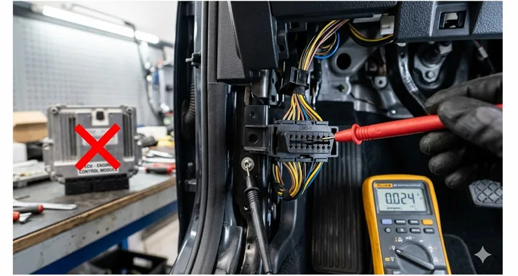
After more than two decades building OBD cable assemblies and troubleshooting field returns, I’ve personally watched far too many perfectly serviceable engine control modules get condemned over a millivolt-level oversight. A bay will chase a stubborn MAF rationality code, an intermittent misfire, or a TPS that refuses to return to closed throttle. They’ll overlay the harness, verify supplies, scope the sensor, and still arrive at the same conclusion: the ECU must have an internal fault. The module gets swapped. The truck rolls out. Three days later it’s back with exactly the same diagnostic trouble codes. The shop is now out two thousand five hundred dollars in parts and at least a day of flat-rate labor—all for a ghost they never measured.
That ghost has a name. It’s called ground offset.
If you’re an automotive diagnostic engineer, a fleet maintenance lead, or a test-bench designer working in the analog space between a sensor element and an ADC, you already know that “ground” is never zero volts everywhere. What still catches even seasoned techs off guard is just how tiny a voltage difference it takes to corrupt an entire control module’s view of the world—and how many perfectly functional ECUs are replaced every month because nobody measured the offset between the OBD connector’s signal ground and the sensor’s remote return. This article pulls that failure mode apart, shows you exactly where it hides on the J1962 DLC, and walks through a diagnostic sequence you can run in minutes—before you ever order a replacement module. It also spells out what a diagnostic cable assembly must deliver to avoid injecting ground offset straight into your measurement chain.
As vehicle architectures move into the 2026 model year and adopt zonal E/E architectures with centralized compute, this failure mode isn’t going away—it’s just relocating. Sensors that once grounded at the engine block now return through smart junction boxes scattered across the chassis. The real estate changes, but the physics of voltage drop don’t. Understanding ground offset has never mattered more for anyone tasked with diagnosing next-generation platforms.
How It Starts: A Real-World Case
Let me walk you through a concrete case from a light-duty diesel fleet vehicle I diagnosed several years back. The unit had a persistent P0107 (MAP sensor circuit low voltage) that had already eaten two MAP sensors and one reflashed ECU. The previous tech had verified a solid 5 V reference at the sensor connector and load-tested the sensor ground circuit with a headlamp bulb—it lit bright and steady. On a Fluke, signal return looked fine. Yet the ECU‘s live data was reporting 0.43 V key-on, engine-off—a value that flatly contradicted the actual barometric pressure.
What finally cracked it wasn’t another scope trace of the sensor. It was a plain voltage measurement between pin 5 (signal ground) of the J1962 DLC and the battery negative post with the engine running and the cooling fan cycling on. That measurement read 0.34 V. At the MAP sensor’s local ground point, the offset reached 0.38 V relative to battery negative. The ECM‘s internal analog-to-digital converter was referencing a “ground” that sat a third of a volt above the true sensor return. That 0.34 V was subtracted directly from the sensor’s output voltage before the ECU ever processed it. The MAP signal appeared dangerously low—not because the sensor was failing, but because the reference had drifted off its mooring.
The fix was not an ECU. The fix was cleaning three chassis ground junctions and replacing a corroded ground strap between the engine block and the firewall. Total cost: less than a hundred dollars in materials and an afternoon of labor. The two thousand five hundred dollars already sunk into the ECU and the prior sensors was money the fleet would never get back.
That’s the problem in a nutshell. And once you’ve seen it a handful of times, you start measuring ground offset at the DLC on every no-code driveability complaint that involves single-ended analog inputs.
The Physics That Makes It Happen
Back to our P0107 case: the physics is straightforward, but the failure mode is completely invisible to a casual check. The MAP sensor, mounted on the intake manifold, was faithfully producing a voltage that tracked barometric pressure. But the engine control module‘s ADC wasn’t reading that voltage alone. It was reading the sensor’s output minus the voltage between its own internal ground reference and the sensor’s local ground return. When that difference—the ground offset—hit 0.34V, the math inside the ECU collapsed. It saw a signal that was physically impossible for a healthy engine, flagged P0107, and the misdiagnosis cascade began. The ECU wasn’t blind; it was being handed corrupted data by a floating reference.
This is the fundamental vulnerability of any single-ended analog input system. The microcontroller’s ADC samples the voltage on its input pin with respect to its own local ground plane—not with respect to the sensor’s remote return. On a modern vehicle, the ECU ground plane bonds to battery negative through a dedicated power ground, but sensor signal returns typically travel a separate low-current path that terminates at the ECU’s analog ground. At the 60-pin or 121-pin ECU connector, you’ll often find distinct ground pins: a power ground for injector drivers and ignition coils, and a quieter analog ground for sensors. On our validation benches, we’ve scoped these pins during load-dump tests—power ground can swing multiple volts, while the analog ground must remain millivolt-stable. The noise and voltage drop from high-current loads on the power ground should, in theory, stay out of the analog ground—unless the vehicle’s bonding strategy has degraded, or unless someone introduces an unintended parallel path through a diagnostic tool or a breakout box. OEM engineers design these systems around a near-perfect ground—a Platonic zero-volt reference. Five years of road salt, thermal cycling, and vibration later, the contact resistance on an unassuming ground lug behind the inner fender has crept from micro-ohms to milliohms. The physics didn’t change; the boundary conditions simply gave way.
That’s where the OBD-II diagnostic connector enters the picture.
The J1962 Ground Pins and Why They Matter
The SAE J1962 standard provides two ground references at the DLC. But what they actually mean in a real fault scenario rarely shows up in a pinout table. This distinction gets even more critical when you realize how easily diagnostic connectors themselves can be misidentified—we’ve documented a case where confusing J1939 Type 1 and Type 2 connectors cost a fleet five thousand dollars in unnecessary parts. For a deeper dive into how ground offset specifically hits heavy-duty networks, we’ve also covered the J1939 ground offset voltage diagnosis in detail.
| Pin | Designation | Textbook Function | The Unspoken Reality (What We See in the Field) |
| 4 | Chassis Ground | Vehicle body/battery (-) path. | The “noisy” ground. On many vehicles, this carries return current for body electronics, lighting, and fuel pumps. High-current spikes here are normal. A stable, low DC offset on Pin 4 to battery (-) is a good sign, but it doesn’t guarantee a clean Pin 5. |
| 5 | Signal Ground | ECU analog/sensor return reference. | This is the sacrosanct reference for your sensors. In a genuinely healthy vehicle, it should be electrically quiet and rarely drift more than 10mV from battery (-). We’ve traced a 150mV, 18Hz ripple on Pin 5 directly back to a failing alternator diode rectifier—an issue that produced no other overt symptoms except ghost-like MAF swings. Treat Pin 5 as the patient’s diagnostic pulse. |
Many aftermarket tools, scan interfaces, and J2534 pass-thru devices bond pin 4 and pin 5 together inside the cable or the tool itself. From a purely digital communication standpoint, this seldom creates an immediate problem, because CAN, ISO 9141-2 K-line, and even J1850 VPW are differential or threshold-based and can shrug off a few hundred millivolts of shift. But the moment you connect an oscilloscope, a data-logger, or a bench power supply referenced to the DLC ground, you can inadvertently bridge the ECU’s analog ground to chassis ground through your test equipment. If the vehicle already harbors a latent ground offset between the engine block and chassis, your tool will either mask it or amplify it—and you’ll spend days chasing your own tail. That’s why in our factory, we don’t stop at a continuity check; we validate ground-loop resistance on first-article samples for every new cable design.
I’ve measured offsets as high as 1.2 V between pin 4 and pin 5 on a running vehicle with a failing alternator rectifier and a compromised engine-to-chassis strap. At that level, sensor readings aren’t just corrupted—the OBD communication itself can become intermittent. An ECU replacement in that scenario is almost a foregone conclusion, because the primary symptom—loss of communication with the scan tool—points straight at the module. Yet the root cause is nothing more than a ground loop. I’ve seen a 0.3V offset on a backbone silently destroy an entire fleet’s data logging, a story we unpacked in the real cost of a 0.3V ground offset on a J1939 backbone
Diagnosing Ground Offset Before You Touch the ECU
When a vehicle acts up with sensor rationality faults, random circuit-high or circuit-low codes scattered across unrelated sensors, or intermittent communication dropouts during high electrical load (cooling fans, glow plugs, ABS pump actuation), you owe it to yourself to eliminate ground offset as a cause before anything else. The procedure takes under ten minutes with a decent multimeter, but it has to be driven by logic, not a checklist. For fleet managers, the math gets ugly fast—we’ve run the numbers on the real fleet cost of ignoring ground offset.
Step 1: The Sanity Check (Pin 4 to Battery Negative)
Before hunting for microvolt-level gremlins, establish a baseline for system health. Set a high-impedance meter (Fluke 87V or equivalent, with at least 1mV resolution) to DC millivolts. Probe the DLC’s Pin 4 (chassis ground) directly to the battery’s negative post. Key-on, engine-off, you want to see less than 50mV. Now, stress the system: crank the engine, let it idle, and cycle every high-current load you can throw at it—high beams, HVAC blower on full, seat heaters, rear defroster. A brief spike during compressor clutch engagement is normal; a sustained jump to 200mV is your first hard red flag. That tells you a high-current return path is compromised before you’ve even touched the sensitive signal ground.
Step 2: The Revealing Measurement (Pin 5 to Battery Negative)
Move the positive probe to Pin 5. Under the same conditions, this should track battery negative tightly—ideally below 20mV. Anything above 50mV deserves a hard look. I’ve seen multiple OEMs specify a maximum ECU analog ground offset of just 10mV across all operating conditions. If you’re reading 150mV or more on Pin 5 at warm idle with the fan cycling, you’ve got a sensor-corrupting offset, and you haven’t yet touched a single sensor connector. This common-mode voltage shift is often invisible without a scope, which is why we’ve published a dedicated guide on how to use an oscilloscope to diagnose a J1939 common-mode voltage shift from ground offset.
Step 3: The Isolation Test (Pin 5 to Pin 4)
Measure the voltage difference between Pin 5 and Pin 4. A 0mV reading may mean the two pins are shorted together inside your cable or tool; that isn’t automatically a fault, but it changes how you interpret the vehicle’s grounding. A reading above 100mV between Pin 5 and Pin 4 points to a significant voltage gradient that will distort any single-ended measurement referenced to Pin 5. This is often the moment you realize the scan tool’s internal ground bonding has been masking the vehicle’s true offset.
Step 4: Move the Reference to the Engine Block
Repeat the Pin 5 measurement with the meter’s negative lead on a clean engine lifting bracket or bare metal. If the offset grows noticeably compared to battery negative, your engine ground strap becomes the prime suspect. Don’t just verify continuity; look for a voltage drop under load.
Step 5: Measure Across the Ground Strap Under Load
A DC millivolt measurement taken directly across the engine-to-chassis ground strap while the starter cranks or the alternator charges will tell you everything you need to know about that connection. I’ve condemned straps that measured perfect continuity with a multimeter yet dropped over 400mV during cranking. That’s 400mV of offset imposed on every single-ended sensor in the engine bay.
Common Measurement Traps
- Using a power probe or a test light to “check ground.” This only proves the circuit can pass current; it tells you nothing about a millivolt-level ground offset at the ADC input.
- Measuring with the DLC breakout box still in series without removing internal jumpers. Many breakout boxes tie pin 4 and pin 5 together. Remove that jumper when diagnosing offset, or you’ll mask the vehicle’s real ground loop.
- Testing offset only on a stone-cold engine. Some ground faults are purely thermal. Let the engine bay reach full operating temperature and flex the harness while watching the meter for drifting millivolts.
If you find an offset that exceeds the OEM guideline—and if you don’t have the OEM spec, adopt 50mV as a working limit—do not replace the ECU. Restore the ground path. For a complete walkthrough of this diagnostic sequence, see our step-by-step guide on how to diagnose J1939 ground offset.
Where the OBD Cable Itself Introduces Offset
There’s another layer here that rarely gets airtime outside manufacturing and engineering circles: the diagnostic cable itself can become the source of offset, particularly when you’re assembling a long-run bench harness, a fleet telematics installation, or a production-line test fixture.
A poorly built OBD extension cable will use undersized conductors for the ground pins, or worse, will daisy-chain pin 4 and pin 5 with a single wire that carries both the communication return current and the tool’s power supply return. Plug a power-hungry VCI (Vehicle Communication Interface) into that cable, and the voltage drop along the ground wire creates an artificial offset exactly where the ECU’s analog ground is sampled. In our incoming QC inspections, we’ve torn down failed cables where the ground wire measured 0.7 Ω end-to-end; with a 500 mA VCI draw, that’s 350 mV of drop injected straight at the DLC before the signal even reaches the tool.
This is why cable design matters in ways a simple continuity beep can never reveal. A proper diagnostic cable assembly should:
- Use dedicated conductors for pin 4 and pin 5 with sufficient AWG to keep loop resistance under 0.1 Ω over the full cable length
- Maintain pin 4-to-chassis and pin 5-to-signal-ground separation throughout the harness, unless a specific bonding strategy is required by the tool
- Be 100% continuity and short-circuit tested at the factory, not merely sample-tested
- Use full-plastic overmolded connectors that prevent moisture ingress and pin-to-pin leakage currents—leakage that can reach several microamps and create offset on high-impedance analog inputs
I’m underscoring this because when you specify an OBD cable assembly for a diagnostic platform, an ECU programming bench, or a fleet tracking device that reads analog sensor data, you’re not just buying wire and two connectors. You’re buying a precision component that sits in series with a measurement system that cares about millivolts. Get it wrong, and you’ll generate phantom faults that no amount of software filtering can fully erase. For heavy-duty applications where cabling faces extreme environmental stress, our guide on forestry J1939 harness protection strategies is a practical resource.
How to Be Certain You’ve Fixed It
After you’ve cleaned every ground junction, replaced any suspect straps, and confirmed the offset has vanished at the DLC, clear the DTCs and complete a full drive cycle. Then repeat the pin-4 and pin-5 voltage measurements under all the high-load conditions that originally set the code. If the offset remains below 50 mV and the rationality faults don’t come back, the repair is confirmed.
One caution: some ECUs will “learn” a corrupted sensor transfer function over time. If a MAP sensor spent weeks reading low because of ground offset, the fuel trims may have adapted accordingly. After the fix, it’s wise to reset fuel adaptives and force the ECU to relearn from clean sensor data. Otherwise, you might briefly see a lean or rich condition that masks an otherwise successful repair.
How We Engineer Ground Offset Out of the Cable
This is where factory-level choices cascade all the way down to the service bay. As a direct manufacturer with over twenty years of producing diagnostic cable assemblies, we’ve seen firsthand what happens when a cable ignores the analog ground path. Our production floor doesn’t just crimp terminals—we validate ground-loop resistance on first-article samples for every new cable design. But the real differentiator lives in details that rarely appear on a spec sheet.
The single greatest long-term threat to a millivolt-level ground path is humidity-driven oxidation on bare copper, starting long before the wire enters the assembly line. A 0.5% increase in crimp resistance from a tarnished conductor today becomes a 100mV offset in a 3-meter bench harness a year from now. That’s why our raw cable stock is stored in a climate-monitored, 5S-managed environment, making sure the copper that enters your assembly is as clean as the day it was drawn. Every reel of wire is traceable to its lot number, and AWG is verified on arrival, because a 0.5 mm² conductor sold as 0.75 mm² will double your voltage drop before you even notice.
We deliberately specify a full-plastic, RoHS-compliant connector body, not as a cost play, but to eliminate a parasitic leakage path you won’t find on any bill of materials. Metal-shell connectors, after years of salt spray and humidity, can develop leakage currents in the microamp range. For a high-impedance analog sensor input, a few microamps across a compromised dielectric is enough to generate a measurable and thoroughly misleading ground offset. Our design removes that variable completely, with UL-rated materials and CE and REACH compliance ensuring an electrically transparent cable over its entire service life.
We don’t AQL-sample our 500VDC insulation resistance test; we run it on 100% of assemblies. Because the one cable shorting Pin 4 to Pin 5 through moisture ingress in a batch of a thousand won’t show up in a random sample, but it will absolutely wreck the day of the engineer trying to flash an ECU on a test bench in Stuttgart. Every assembly passes a four-step quality inspection—incoming material check, first-article approval, in-process electrical test, and final outgoing audit—backed by an ISO 9001, ISO 14001, and IATF 16949 quality management system that is automotive-grade from raw material to shipping. This commitment to quality also aligns with our ISO 14001 environmental management certification.
When you work with us on an OEM basis, you can specify exactly what your application demands: custom logo, brand colors, cable length in one-meter increments, AWG tailored to your current loop, and pinout configuration that keeps signal and power grounds routed the way your engineering team intended. Our engineering support group will review your schematic and flag anything that could introduce offset—because we’d much rather fix a design on paper than after a thousand cables have landed on your production line.
If your team is diagnosing phantom sensor faults on a test bench or integrating an OBD interface where a single millivolt of ground shift is one too many, let’s talk. We’re not here to deliver a sales pitch; we’re here to review your pinout and application with the same engineering scrutiny you apply to your own designs. Reach out directly on WhatsApp or send your project specifications through our contact page.
Frequently Asked Questions
1. What exactly is “ground offset” in an automotive context?
Ground offset is the voltage difference between two points that are supposed to be at the same reference potential—typically the ECU’s internal analog ground and the sensor’s local return path. It’s measured in millivolts but can corrupt any single-ended analog measurement the ECU relies on.
2. How can ground offset make a healthy ECU look faulty?
If the ECU’s analog ground sits 300 mV above the sensor’s local ground, a sensor output of 2.5 V appears to the ECU as 2.2 V. The ECU interprets this as an out-of-range signal, sets a circuit-high or circuit-low DTC, and the technician may conclude the internal ADC has failed when in fact the reference has shifted.
3. What is the maximum acceptable offset between OBD pin 5 and battery negative?
Many OEM engineering standards specify less than 10 mV under static conditions and below 50 mV under full electrical load. If you don’t have the manufacturer’s spec, treat anything above 50 mV on pin 5 as a problem that needs to be located and corrected before proceeding with any sensor or ECU diagnosis.
4. Can a bad OBD extension cable cause ground offset?
Yes. High-resistance ground conductors, undersized AWG, and improper bonding of pin 4 and pin 5 inside the cable can all create an artificial voltage drop that shifts the reference for any tool connected to the DLC. This can mask or mimic a real vehicle ground fault.
5. Why do some cables connect pin 4 and pin 5 together?
Some low-cost cables tie them together to reduce wire count or because the tool’s design assumes a common ground. In a vehicle with zero offset this works; in the real world it can create a ground loop and make offset measurement impossible. For precision work, we recommend keeping them separated.
6. How do I measure ground offset with a standard multimeter?
Set your meter to DC millivolts. Measure between pin 5 of the DLC and the battery negative post, then between pin 5 and a clean point on the engine block. Activate high-current loads while watching the reading. Any sustained value above 50 mV should be investigated. Always use a meter with high input impedance to avoid loading the circuit.
7. What are the symptoms I’m likely to see if ground offset is the issue?
Look for multiple, seemingly unrelated sensor rationality DTCs (P0106–P0108, P0120–P0123, P0220–P0223), communication timeouts during high electrical loads, erratic live data on scan tools, and repeat ECU replacements that never solve the problem.
8. Does a CAN bus system eliminate ground offset problems?
CAN is differential and tolerates a certain level of ground shift between nodes, typically up to a few volts, so data corruption from offset is less common. However, many sensors that feed into the ECU via analog inputs or SENT protocol are still single-ended referenced to the ECU analog ground, so offset remains a concern for sensor signal integrity even in vehicles with CAN architecture.
9. What’s the difference between a vehicle ground offset and a ground loop introduced by my test equipment?
A vehicle ground offset exists independently of your tools. A ground loop is created when your tool or its power supply provides an additional return path that alters the offset or injects noise. If you connect a laptop or a scope probe ground to pin 5 while the laptop charger is plugged into a mains outlet, you’ve almost certainly introduced a loop. Always check with the tool both connected and disconnected.
10. I’m designing a diagnostic product. How can your factory help me avoid ground offset problems in my cabling?
We’ll review your pinout and intended signal routing during the engineering phase. We can recommend AWG sizing, separate ground conductor strategies, and connector selection to keep loop resistance to a minimum. With full OEM customization capability—logo, color, length, and pinout—and all relevant certifications (ISO 9001, IATF 16949, UL, CE, RoHS, REACH) backing every production run, you get a cable that is an instrumentation-grade component, not a commodity accessory.
If you need a diagnostic cable assembly where ground is treated as a precision signal, not an afterthought, talk to our engineers. We’re a direct factory with over twenty years of automotive-grade production experience, and we support OEM customers who can’t afford millivolt-level guesswork in their harness design. Reach out via WhatsApp for a direct technical discussion, or send us your requirements through our contact page.
WhatsApp: Chat with us
Contact Page: obd-cable.com/contact/
