

Author Note: I’m writing this because last month I watched a fleet operator replace four engine ECUs in two weeks. Every one of them failed the same way. The multimeter said the ground was fine. It wasn’t. This article is what I wish someone had handed me fifteen years ago.
If you work with J1939 long enough, you develop a healthy paranoia about certain things. Water in connectors. Chafed harnesses on frame rails. The apprentice who decided to “fix” a Deutsch connector with a pair of pliers from his glovebox.
But there’s one problem that doesn’t announce itself with visible damage or fault codes that make sense. It corrupts data silently. It causes intermittent J1939 failures that somehow never happen when the machine is in the shop. It makes good technicians doubt their J1939 diagnostic skills and bad ones start replacing parts at random.
I’m talking about ground offset—the voltage differential between what different ECUs on the J1939 network believe is “zero volts.”
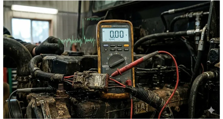
And here’s the thing that catches people: your multimeter will tell you everything is fine. It’s not lying to you. It just can’t see the problem fast enough. This is where an oscilloscope vs multimeter for CAN bus comparison becomes your first hard lesson, and I learned it the expensive way about twelve years ago on a forestry machine that would randomly derate and log a J1939 communications failure—but only when the track tension was high and the hydraulic pumps were at full stroke. Restart the machine, clear the codes, and it would run perfectly for anywhere from three hours to three days. The customer was ready to torch the thing.
The problem wasn’t the CAN bus wiring, the terminators, or any of the usual suspects. What was actually happening was a 1.8-volt ground offset that appeared only under specific load conditions, lasted for milliseconds, and disappeared before any standard diagnostic tool could catch it.
That machine taught me to distrust voltage readings taken with the network asleep. A machine rolled into our shop years later—a mining truck this time—with the exact same symptom pattern but on a totally different platform. Then an agricultural harvester. Then a marine propulsion system. Then one very expensive generator set that nearly got several engineers fired. Same root mechanism, different wrapping paper.
Let me walk you through what ground offset actually is, why standard diagnostic approaches fail to catch it, and how to find it when it’s hiding from your equipment.
What Ground Offset Actually Means in a J1939 Context—And Why the Definition Matters
Most training materials define ground offset in a technically correct but practically useless way: “a difference in ground potential between two or more nodes on the network.”
That’s accurate. It’s also what gets technicians stuck because it makes them think in terms of static measurements.
Here’s what I’ve found more useful: ground offset is any condition where the reference voltage at one ECU’s CAN transceiver differs from the reference voltage at another ECU’s transceiver by enough to shift the logic threshold for dominant and recessive bit states.
The J1939 physical layer uses a differential signal. CAN_H and CAN_L voltages are measured relative to each other, not relative to ground. In theory, this makes the bus immune to ground offsets within a certain range. The keyword is “within a certain range.”
Here’s what the datasheets won’t tell you plainly: that 1.5 to 2.0 volt common-mode tolerance everyone quotes from ISO 11898-2? That number assumes a brand-new transceiver at 25°C ambient with a clean supply rail. Take the same transceiver into an engine bay that cycles between -20°C and 90°C for eight years, feed it power that’s got some alternator ripple on it, and the actual tolerance might be half the datasheet value. I’ve measured it.
In the real world—on this machine, right now, with this specific combination of aging wiring, vibration, temperature, and connector corrosion—you might have much less margin than the datasheet suggests.
A few cases I’ve documented:
- A 1.2-volt offset that shouldn’t have been a problem, except the bus was also terminated slightly wrong and the CAN_H driver in one ECU was getting weak. Combined, those three marginal conditions created intermittent bit errors that looked exactly like a failing ECU.
- A 0.9-volt offset that only appeared above 80°C ambient in the engine bay. Cold machine? Perfect communications. Hot machine after three hours of full-load operation? Random J1939 timeout errors on the transmission controller.
- A 2.3-volt offset caused by a ground strap that looked perfectly fine externally but had corroded internally underneath the heat shrink. Resistance measured 0.2 ohms with a meter. Under 30 amps of ground return current, it became a different story.
The lesson I took from all of these: ground offset is not one problem. It’s a category of problems that all share the same symptom—the network works until it doesn’t—but have fundamentally different root causes.
The Diagnostic Gap That Catches Everyone
Let me describe the scenario that led to this article.
A customer has a machine—let’s say a large agricultural sprayer with a J1939 network connecting the engine ECU, transmission controller, display, GPS receiver, rate controller, and several I/O modules. The machine has an intermittent fault. Sometimes, usually after several hours of operation, the display shows “Engine Communication Lost” and the system goes into a limp mode. Restart and everything resets.
The technician arrives with a standard diagnostic kit: a good-quality multimeter, maybe a scope if they’re well-equipped. They check resistance across CAN_H and CAN_L at the diagnostic connector. It reads 60 ohms, which is what you’d expect with two 120-ohm terminators in parallel—exactly how the J1939 backbone design and 60 ohm derate principle is supposed to work. They check the recessive voltages—both lines sitting where they should. Everything passes the static checklist. They check for shorts, opens, chafing. Nothing obvious. They clear the fault codes and the machine runs perfectly during the test drive.
So they do what any reasonable person would do: they suspect the engine ECU, open a warranty claim, and replace it.
The machine works for three days and the problem returns.
This is the diagnostic gap. Standard J1939 troubleshooting procedures are designed to find hard faults—opens, shorts, failed terminators, dead ECUs. They are not designed to find dynamic ground offsets that only occur under specific operating conditions.This same gap between static test-pass and real-world failure dominates another costly J1939 problem: network topology defects where termination placement and stub length bleed $15,000 per year from fleet maintenance budgets.
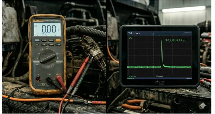
Here’s something I learned the hard way: a Fluke 87V in min/max mode still has a 100-millisecond capture window. That’s fast by multimeter standards. But the ground offset I was chasing on that forestry machine lasted somewhere between 20 and 40 milliseconds—shorter than the capture window. The meter recorded a max of 0.3V. The scope later showed 1.8V.
The difference was six ECU replacements and about $14,000 in parts. This is exactly the kind of J1939 physical layer troubleshooting that a 60 ohm waveform can expose when a meter completely fails.
An oscilloscope set up to trigger on CAN frames can catch this—but only if you know to look for it, and only if you’re monitoring the right signals in the right way. Most field technicians aren’t setting up differential probes to measure ground offset between ECU locations. They’re looking at CAN_H and CAN_L relative to ground, and that won’t necessarily reveal a ground shift if both lines shift together.
This is exactly how the forestry machine I mentioned earlier defeated multiple diagnostic attempts. The ground offset was appearing on the engine ECU ground reference, caused by high-current loads—specifically the hydraulic pump solenoids—returning current through a compromised path. When the pumps went to full stroke, the ground at the engine block would momentarily lift relative to chassis ground. The CAN transceiver inside the engine ECU, referenced to engine block ground, would see the bus voltages shift enough to misread bits. The display, referenced to chassis ground, was seeing a different reality entirely.
The forestry machine only faulted when hydraulic oil temperature crossed 70°C. Cold machine: perfect. That detail misled three different diagnostic attempts before we figured out it wasn’t the temperature itself—it was the pump stroke calibration map switching to a higher PWM duty cycle at that temperature threshold. The higher duty cycle meant more ground return current, which meant a larger voltage drop across the compromised ground path.
By the time we stopped the machine and connected diagnostic equipment, the condition had passed. The meter showed zero offset. The scope trace looked clean.
It took a data logger with isolated inputs, sampling at 1 kHz, running continuously for six hours, to catch the event.
How to Actually Find It: A Method That Works When Standard Procedures Don’t
I’ve refined this approach over years of chasing intermittent J1939 problems. It’s not the fastest method on paper, but it’s the one that consistently finds ground offset problems when faster methods fail.
What You Need for Ground Offset Diagnosis
You cannot do this properly with just a multimeter. I’ve tried. You need at minimum:
- A two-channel or four-channel oscilloscope—a basic Picoscope or similar is fine; you don’t need lab-grade equipment
- At least one differential probe or two standard probes that you’re willing to use in differential mode, with the scope’s math function handling the subtraction
- Back-probe pins or breakout harnesses so you can access signals without damaging connectors
- A way to create a common reference point—I use a long wire run from the battery negative terminal to wherever I’m measuring
A current clamp rated for DC, especially one sensitive enough to resolve small currents in the 100 mA range, will dramatically speed up diagnosis if you suspect high-resistance ground paths. I learned to bring one on every call after the third time I spent hours looking for a ground fault that would have shown up in five minutes with a current measurement.
The Reference Point Problem
Before you measure anything, you need to decide what “ground” means for your measurement.
Most technicians clip their scope ground lead to the nearest chassis point. For ground offset diagnosis, this is exactly wrong. If the chassis itself has voltage gradients across it—and it will, under load, because steel has resistance—you’re measuring relative to a moving target.
Here’s what I do instead: run a dedicated reference wire from the battery negative terminal. This is your measurement reference. It doesn’t carry any current except your measurements. Label it clearly so nobody disconnects it thinking it’s a forgotten ground strap. I use a bright orange wire that’s impossible to mistake for anything stock.
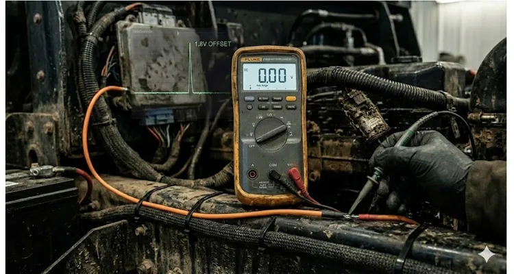
With this reference established, every measurement you make is relative to the same point. Now you can compare voltages at different locations and know that any difference is real, not an artifact of your measurement setup.
The Step-by-Step Diagnostic Sequence for J1939 Ground Offset
This is the sequence I follow. Adapt it to your machine’s architecture, but keep the logic.
Step 1: Map the ground topology before touching anything.
Draw it out. Where does each ECU get its ground? Engine block? Chassis stud? Dedicated return wire to the battery? You need to know this before you can diagnose it. I’ve wasted hours troubleshooting a “ground offset” that turned out to be an expected difference because one ECU was grounded through the engine block and another through a completely separate chassis point, and nobody had documented it.
If you don’t have the machine’s ground distribution diagram, this is the step where you either find it or make your own. Trace wires. Look for ground studs. Note what shares a connection point.
Step 2: Measure static ground offset with the machine off—key off, all loads off, network asleep.
Connect your scope or meter between the reference wire at battery negative and each ECU’s ground pin. Note the readings. They should all be within about 50 mV of each other and close to zero relative to the battery. If you see more than 100 mV of difference with everything off and the network asleep, you have a hard ground fault—corrosion, a loose connection, or a damaged wire. Find it before proceeding. The machine is easier to work on when it’s not running.
Step 3: Measure with key on, engine off, all loads off.
Now the ECUs are powered up and drawing their normal operating currents. Ground offsets may increase slightly due to current flowing through ground paths. Anything more than 200-300 mV at this stage warrants investigation. Pay particular attention to ECUs that show a significant change from the Step 2 measurement—this indicates their ground path has meaningful resistance.
Step 4: Measure with the machine running, and methodically add loads.
This is where intermittent ground offsets reveal themselves. You need to monitor ground potential at each ECU—relative to your battery-negative reference—while the machine is operating and while you sequentially activate high-current loads:
- Hydraulic pumps and solenoids
- Electric cooling fans
- Air conditioning compressor clutch
- Lighting systems
- Any electric motor or heater
Watch not just the steady-state voltage but the transient behavior—the moment when a load switches on or off. A PWM-controlled hydraulic solenoid, for example, will create ground current pulses at the PWM frequency. If the ground path has impedance, those pulses will appear as voltage noise on the local ground. This is where a J1939 voltage drop field test becomes your most reliable tool for revealing what an ohmmeter never will.
What you’re looking for: any ECU ground that shifts by more than 0.5V under load, or any ECU ground that shows noise or transients correlating with load switching events.
Step 5: If you find a candidate, measure between ECUs directly.
Once you’ve identified that Engine ECU ground lifts 1.2V when the cooling fan engages, and Display ECU ground stays solid, you’ve found your problem. But confirm by measuring directly between the two ground pins. Your scope’s differential measurement will show the 1.2V offset directly.
Now, and only now, do you start looking for the physical cause.
Step 6: Isolate whether the problem is in the positive side or the ground side.
This is a step many people skip. A ground offset can be caused by:
- High resistance in the ECU’s ground path—the return current develops a voltage
- High resistance in the ECU’s power supply path—the supply voltage sags, pulling the ground reference with it through internal paths
- Shared ground paths carrying current from unrelated loads—the ground point itself is clean, but the current flowing through it creates a voltage
To isolate: measure the ECU’s supply voltage at the ECU connector, between power and ground pins, at the same time as you measure the ground offset. If the supply voltage is dropping when the ground lifts, you likely have a high-resistance supply path. If the supply voltage is stable while ground is lifting, the problem is in the ground path specifically.
The Five Most Common Mistakes I See—And Have Made Myself
1. Using the nearest piece of metal as a measurement reference.
I covered this above, but it bears repeating because it’s the single most common diagnostic error with ground offset problems. If you clip your ground lead to a chassis bolt that happens to be carrying current, your measurements are meaningless. The bolt might be at 0.5V relative to battery negative, and you’d never know. Establish a real reference or don’t bother measuring.
2. Measuring ground resistance with a multimeter and calling it good.
A multimeter measures resistance by passing a tiny current—typically 1 mA or less—through the circuit and measuring the voltage drop. This tells you almost nothing about how the ground path will behave when it’s carrying 20 amps of starter current, or 30 amps of glow plug current, or the pulsed current from a PWM hydraulic valve.
A ground strap that measures 0.1 ohms on a meter might have a thin, corroded strand inside the crimp that becomes 0.5 ohms under thermal stress. It measures fine cold. Put 20 amps through it for 30 minutes and the resistance changes. This is exactly why a voltage drop test under load—the kind you learn when you master a J1939 physical layer ROI with basic tools approach—beats an ohmmeter every single time.
An ohmmeter is a screening tool. It can find open circuits and very high resistances. It cannot validate a ground path as good. For that, you need to measure voltage drop under load.
3. Assuming the bus is “differential so ground doesn’t matter.”
The differential nature of CAN bus provides common-mode rejection—up to a point. Every transceiver has a common-mode input range specification. Exceed it, and the receiver cannot reliably distinguish between dominant and recessive bits.
What’s less appreciated is that common-mode rejection degrades as the transceiver ages. We documented a case where ECUs worked fine for years with a marginal ground offset, then started failing as the transceiver’s input range narrowed due to semiconductor aging and thermal cycling. The ground offset didn’t change. The ECU’s tolerance for it did. Every thermal cycle from cold-soak winter starts to full-load summer operation nibbles away at that tolerance. It’s not a cliff. It’s a slow erosion, and by the time you see symptoms, the transceiver has been running on borrowed margin for months.
4. Ignoring that ground offset is often a symptom, not the root cause.
When you find a ground offset, the natural impulse is to fix the ground path—add a ground strap, clean connections, run a new wire. That’s often the right fix. But sometimes the root cause is elsewhere.
I’ve watched a technician add a ground strap and “fix” a machine in 15 minutes. Two weeks later the alternator failed completely—not because the ground strap caused it, but because the alternator’s rectifier diodes had been failing for months, creating the AC ripple that was producing the offset. The ground strap didn’t fix the problem. It masked the symptom just long enough for the alternator to finish destroying itself, and then it looked like the strap had failed too. By the time I got involved, nobody knew what was cause and what was effect.
When you find ground offset, ask: is this ground path abnormal, or is something dumping abnormal current into a normal ground path?
5. Chasing values that don’t matter instead of values that do.
The ISO specification says the maximum ground offset is 1.5V to 2.0V. I’ve seen technicians obsess over a 1.4V offset that was perfectly stable and, based on the specific transceivers in use, well within their common-mode range. Meanwhile, they ignored 0.3V of high-frequency noise on the same ground because “it’s only 300 millivolts.”We later documented a case where a stable 0.3V DC ground offset on a J1939 backbone—not noise, just a quiet voltage shift—cost a fleet over nine thousand dollars in unnecessary ECM replacements, a chassis harness, and an instrument cluster. The full diagnostic sequence is in our nine thousand dollar 0.3V ground offset case study.
The absolute magnitude of offset matters, but the characteristics matter more:
- Is it stable or does it change with operating conditions?
- Is it clean DC or is there AC noise riding on it?
- Does it correlate with any specific event or load?
- Is it within the specific transceiver’s documented common-mode range, not just the generic ISO number?
A 1.8V stable, clean offset on a system using transceivers rated for ±5V common-mode is not your problem. A 0.4V offset with 200 mV of switching noise at the PWM frequency of a nearby hydraulic valve? That might very well be your problem.
How to Confirm You’ve Actually Fixed the Ground Offset
The most common post-repair failure mode for ground offset problems is declaring victory prematurely. You find a bad ground, clean it up, measure zero offset with the engine idling, and close the job. A month later, the problem returns and the customer is angrier than before.
Here’s what I do instead:
Validation Under Load: Test the Exact Conditions
Validation must happen under the exact conditions that produced the fault.
If the problem only occurred with hydraulic pumps at full stroke and engine temperature above 85°C, that’s the condition you test. Not idling in the shop. Not after a five-minute run. You need to reproduce the operating point.
I use a data logger with the machine running under load for a full operating cycle. Set up monitoring on the ECU ground you repaired, and on at least one other ECU for comparison. Sample fast enough to catch transients—at least 100 Hz, preferably 1 kHz if you have PWM-controlled loads on the machine. Run the machine until it reaches full operating temperature, then cycle all the high-current loads.
Look at the Trace, Not the Average
A ground offset that occasionally spikes to 1.0V under a specific load transient might average out to 0.05V in your data summary. You need to look at the trace. The spike matters. The average doesn’t.
Test with Safety Margin for Future Corrosion
If you measured a 1.8V offset before repair and now measure 0.1V, that’s excellent. But what happens in six months when the connection develops a little oxidation? What happens when the machine operates in high humidity? What happens when a different load is added to the same ground path?
For a ground repair to be durable, I want to see no more than 200 mV of offset under maximum load and worst-case thermal conditions. That gives margin for aging, corrosion, and the unexpected.
Document Your Ground Offset Repair Completely
This isn’t just for the next technician—though they’ll appreciate it. It’s for you, when the machine comes back with a different problem and someone suggests it might be related. A clear note in the service record, including the measured offset before and after, the loads used for testing, and the specific repair performed, is worth more than any generic “repaired ground connection” entry.
The Related Hardware That Either Solves or Causes Ground Offset Problems
I’m going to mention a few categories of products here, not as a sales pitch, but because the physical layer components you choose determine whether ground offset becomes a recurring nightmare or a non-issue.
Cable Assemblies with Oversized Ground Conductors
This feels obvious, but a surprising number of J1939 harness problems trace back to ground conductors that were sized for steady-state current draw without accounting for inrush or transient loads. If you’re specifying cables—whether as an OEM or for replacement—the ground conductor should be sized with the same attention as the power conductor. A 22 AWG ground return on a device that draws 5 amps may meet the ampacity tables. Under real-world conditions with connector resistance, aging, and temperature, it’s marginal. For a deeper dive on balancing budget and uptime, our J1939 cable TCO fleet procurement guide explains how to avoid false savings from undersized harnesses.
We manufacture cable assemblies where the ground return path is deliberately oversized relative to the minimum specification—not because the standards require it, but because we’ve seen what happens when you push minimum-spec wiring through 10,000 hours of agricultural or construction duty cycles. The difference in reliability is measurable and significant.
Diagnostic Breakout Harnesses for CAN Bus and Ground Offset
If you’re going to diagnose J1939 ground offset problems more than once, invest in or build a proper breakout harness. Something that lets you access CAN_H, CAN_L, power, and ground at each ECU location without piercing wires or back-probing connectors in ways that create new failure points. We build these for specific machine platforms for clients who maintain large fleets. The time savings on the first diagnostic session usually justifies the cost. The approach ties directly into the philosophy behind CAN bus physical layer testing that saves $800 in diagnostic fees—get the right adapter in place once, and you stop chasing your tail.
Connectors That Don’t Become the Failure Point
We’ve cut open failed Deutsch connectors under a microscope. The ones crimped with the correct Deutsch tool show a solid cold-weld between the copper strands and the terminal barrel—no air gaps, no oxide layer, uniform compression. The ones crimped with generic tools show something different: the terminal wings folded over but didn’t weld. Under thermal cycling, those strands develop micro-fretting. Resistance climbs from 2 milliohms to 0.3 ohms, then to 0.8 ohms. The connector looks fine externally. Under load, it’s a resistor.
A tiny amount of moisture ingress over hundreds of thermal cycles accelerates this process and creates exactly the kind of high-resistance ground path that drives ground offset problems. Treat connector assembly as a skilled operation, not an afterthought. Bad crimps and poorly seated seals are the root cause of more ground offset problems than I can count. For a step-by-step reference, our J1939 Deutsch DT/HD connector guide covers the exact tooling and inspection standards that prevent these failures.
Questions I Get Asked About Ground Offset
Q: Can ground offset damage an ECU permanently?
Yes, if it’s severe enough and sustained. The CAN transceiver has internal protection diodes connected to the supply rails. If ground offset forces these diodes into forward bias for extended periods, they can fail. I’ve documented transceivers that worked intermittently for months after a ground offset event, then failed permanently. The failure mode is usually a shorted or partially shorted CAN_H or CAN_L pin to ground or supply.
Q: Will adding a ground strap between the engine block and the chassis fix most ground offset problems?
It fixes a subset of them—specifically those caused by high resistance in the existing engine-to-chassis ground path. It won’t fix offsets caused by resistance in the ECU’s local ground wire, or offsets caused by a failing alternator dumping noise, or offsets caused by a shared ground path carrying current from an unrelated load. I’ve watched a technician add a ground strap and “fix” a machine in 15 minutes. Two weeks later the alternator failed completely—the rectifier diodes had been failing for months, and the strap only masked the symptoms temporarily. A ground strap is a repair, not a diagnosis. Know the difference.
Q: My machine only throws J1939 errors when the outside temperature is below -10°C. Could that be ground offset?
It could be. Cold temperatures increase resistance in most connectors because thermal contraction reduces contact pressure, and make wiring harnesses stiffer which increases strain on connections. But cold-weather-only faults can also be caused by condensation freezing and thawing inside connectors, or by ECUs operating near the edge of their temperature spec. You need to measure, not guess. And if you do measure in cold conditions, let the machine cold-soak properly before testing—warming it up first will hide the very condition you’re chasing.
Q: How do I prevent ground offset from happening?
Design for it from the start. Use separate ground returns for high-current loads and communications ECUs where practical. Specify ground conductors with margin. Use quality connectors assembled with proper tooling. Route harnesses away from heat, vibration, and moisture. Validate under load during commissioning, not just at idle. On existing machines that are already in the field, focus on connector integrity and ground path maintenance as part of scheduled service.
Q: Can a bad termination resistor cause symptoms that look like ground offset?
Yes, and this is one of the most common misdiagnoses. An incorrect or failed termination changes the bus impedance and reduces noise margin. A bus that’s marginally terminated may work fine until a small ground offset—which would be tolerated by a properly terminated bus—causes errors. If you find ground offset, check termination resistance first. It’s a two-minute test that rules out a common compounding factor. I’ve seen machines where fixing the termination made the ground offset “disappear”—not because the offset went away, but because the bus regained enough margin to tolerate it. If you want to avoid expensive missteps, our breakdown of J1939 termination mistakes and ECU repair cost covers the most frequent errors that get blamed on ECUs.
Q: What’s the difference between ground offset and a ground loop?
Ground offset is a voltage difference between two ground reference points. A ground loop is a specific cause of ground offset: when two points are connected through multiple paths—intentional grounds plus, say, the shield of a cable that’s grounded at both ends—current can circulate through the loop, creating voltage differences. Ground loops are one cause of ground offset, but not the only one.
Q: Should I measure CAN_H and CAN_L relative to ground, or relative to each other?
Both, but for different reasons. Measure CAN_H and CAN_L relative to each other differentially to verify the bus signal quality. Measure CAN_H and CAN_L relative to the local ECU ground to verify that the signals are within the transceiver’s common-mode range. For ground offset diagnosis specifically, measure ECU ground relative to a common reference at battery negative.
Q: What’s the fastest way to rule in or rule out ground offset as the cause of an intermittent J1939 problem?
Monitor the network error counters if your diagnostic tool supports them. Most J1939 controllers track transmit and receive error counts. If you see the receive error count incrementing on a specific ECU during the fault event, especially while monitoring ground potential shows a correlation, you have strong evidence. But many field-level diagnostic tools don’t expose these counters, so you may need to measure directly with a scope and a proper reference. This is where a structured approach like the one in J1939 data link error diagnosis in 20 minutes can help you eliminate guesswork.
Q: Is this problem becoming more or less common with newer equipment?
I see it more often on older machines where connections have degraded over time, which is expected. But I also run into it on newer machines with high-current electric accessories—electric cooling fans, electric HVAC compressors, electric power steering—that share ground paths with the J1939 network. The currents are higher than they were on machines designed 20 years ago, and ground path design hasn’t always kept pace. Some of the worst ground offset problems I’ve diagnosed were on machines less than two years old.
If You’re Dealing With This Right Now
Ground offset problems are frustrating because they resist standard diagnostic approaches. If you’ve read this far and you’re actively fighting one, here’s what I’d suggest as next steps:
Get a scope on the ground pins while the machine is operating under the conditions that trigger the fault. Use a proper reference—that orange wire from battery negative. Watch for transients, not just steady-state values. Check the ground path resistance under actual load, not with an ohmmeter. And if you need harnesses, connectors, or cable assemblies that won’t become the next failure point, we build them to the environment they’ll actually operate in, not just to pass a spec sheet review.
If you want to discuss a specific machine or application, or if you need diagnostic support on a J1939 issue that’s been eating your time, you can reach me directly through our contact page. I read every message. If I can’t help, I’ll tell you that too.
For faster back-and-forth, especially if you’re in the middle of a diagnosis and need quick input: message us on WhatsApp. We do OEM cable assembly and harness work for equipment manufacturers globally—we’re a factory, not a reseller—so if you need something built to your specification rather than off-the-shelf, we can have that conversation.
About the author: I’ve been diagnosing and repairing J1939 networks on heavy equipment since 2006. I currently work on the engineering side of a cable and harness manufacturing team. I write about CAN bus diagnostics because I’ve made most of the mistakes myself and see no reason anyone else should have to repeat them.
Our manufacturing facility: certified to ISO 9001, ISO 14001, and IATF 16949. RoHS-compliant materials. 100% continuity and hipot testing on every assembly. Four-stage quality inspection before anything leaves the floor. Direct factory—we’re not a reseller.
