

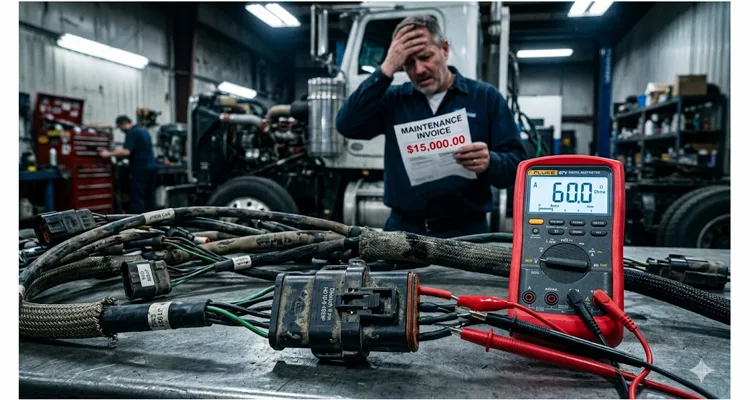
You hear the service manager before you ever see the work order. “It’s back. Same truck. Third time this month.” The fault log tells a story you’ve lived through more times than you’d like: J1939 timeouts on the aftertreatment node, intermittent communication loss, and not a single hard component failure to point a finger at. The cab harness already wears a zip-tie graveyard left behind by the last technician who tried “tightening up the connections.” You disconnect the battery, pin C to D on the 9-pin Deutsch diagnostic connector, and watch the meter lock in at a textbook 60.0 ohms. The customer stands in the bay doorway, arms folded, demanding to know why he’s paying for another DEF pump when the previous one didn’t survive 800 miles. The real problem isn’t hiding on that meter screen.
I’ve traced this exact scenario across more service bays than I care to count, and the root cause is rarely a failed ECU or corrupted flash file. The culprit lives in the physical network topology itself: termination resistors anchored where the J1939 specification never intended them to be, and stubs that run 40% longer than the standard permits. The financial bleed from these oversights tallies roughly $15,000 per year per fleet—money burned on unnecessary maintenance labor, misdiagnosed component swaps, and downtime that should never have been scheduled in the first place. I’ve documented this exact phantom fault pattern repeatedly in the field, where the bus passes every static test yet fails under real operating conditions—a scenario we dissect further in our analysis of J1939 termination mistakes and ECU repair costs.
The cost isn’t the resistor. The cost is chasing ghosts through the wiring harness.
The termination resistor itself runs maybe $1.50 from any Deutsch supplier. The 30-inch stub someone spliced in because “the connector wouldn’t reach” consumes a few feet of twisted pair off the reel. What pushes the bill toward $15,000 is the technician who burns six hours swapping ECMs that tested perfectly on the bench, the mobile service call dispatched at 2 AM, the revenue lost while a concrete mixer sits silent, and the warranty claim filed against a transmission controller that was never defective in the first place.
Unplanned downtime in heavy trucking clocks in around $760 in lost revenue per hour. A single J1939 network failure that demands a full shift to diagnose properly—not the “clear codes and hope” routine—burns through $6,000 before you’ve laid a hand on the harness. Let that happen twice in a calendar year, and the arithmetic turns uncomfortable fast. Factor in the collateral damage from misdiagnosis, and the number climbs even higher.
This article is not another tutorial on “how to measure 60 ohms.” That ground has been covered exhaustively elsewhere. What I want to dissect is why the topology you inherit from a harness manufacturer or a field modification is almost guaranteed to be compromised, how those deviations convert directly into operating losses, and what a properly executed J1939 backbone demands—from the factory floor all the way to the service bay.
The Two Mistakes That Drain Maintenance Budgets
Let’s be precise. Not every J1939 network problem originates from topology. You contend with pin fretting inside the Deutsch connectors. You chase ground offsets born from corroded chassis bonds. You wrestle with the inevitable carnage from road debris and exhaust heat cycling. Yet the two mistakes I observe recurring across every brand of equipment—from Peterbilt to Caterpillar to Volvo—are the following.
Mistake 1: Termination Resistors Anchored in the Wrong Location
The J1939 standard leaves no room for interpretation. A 120-ohm resistor must be installed at each extreme end of the backbone—not at the ends of stubs, not at some convenient junction box location, and absolutely not inside an ECU unless that particular ECU physically occupies the farthest extremity of the backbone.
Visualize the backbone as a pressurized hydraulic circuit. The termination resistor is the cap sealing the line’s end. If you mount that cap on a tee fitting two meters down a dead-end branch, the main line beyond that tee runs uncapped. Pressure pulses strike the open end and ricochet backward, generating hydraulic noise that the ECMs cannot filter. At 250 kbps, you don’t hear the noise audibly—you simply watch modules drop offline for milliseconds at a stretch. This is the exact mechanism behind what we call a J1939 bit sampling error and reflection bus-off event.
I’ve encountered termination resistors placed on a stub located six feet away from the backbone because “that’s where the connector landed.” The resistance measurement at the diagnostic connector still reads 60 ohms. The bus is terminated. It’s merely terminated in the wrong physical location, creating a stub that extends beyond the termination point—functionally an unterminated stub with a resistor dangling off its end. The network behaves flawlessly until the engine spins past 1,800 RPM and vibration starts working that inadequately supported stub. Then the reflection pattern shifts, bit errors accumulate, and the transmission controller drops off the bus without warning.
This failure mode is particularly treacherous because it’s both intermittent and thermally dependent. The bus passes every static resistance test you throw at it on the shop floor. It only falters when the vehicle is in motion, and often only after ambient temperatures push the cable impedance just beyond the tolerance window. A technician who never physically traces the backbone end-to-end will never uncover it. For a deeper dive into diagnosing these elusive failures, see our guide on J1939 physical layer troubleshooting beyond the 60-ohm waveform.
Mistake 2: Stubs That Exceed the 1-Meter Limit
Under J1939-11, the maximum stub length permitted is 1 meter—roughly 39 inches. This is not a suggestion; it’s a hard boundary derived from the signal propagation velocity in twisted-pair copper at the 250 kbps data rate.
Every meter of stub introduces roughly 5 to 6 nanoseconds of propagation delay. Set against a 4-microsecond bit period at 250 kbps, that sounds negligible. But here is what actually unfolds: the stub creates an impedance discontinuity. The signal traveling down the backbone reaches the stub junction, divides, journeys to the end of the stub, reflects, and rejoins the backbone signal—delayed by the round-trip propagation time of that stub. For a 1.8-meter stub, that reflection returns approximately 18 to 21 nanoseconds after the original edge.
At 250 kbps, the CAN controller samples the bit state at roughly 87.5% of the bit period—about 3,500 nanoseconds after the edge. A 21-nanosecond reflection seems irrelevant at that timescale. But the real issue isn’t absolute delay; it’s edge distortion. The reflection overlays the rising or falling edge of the CAN signal, producing a “shelf” or “step” that alters the threshold-crossing time. If that distortion forces the edge outside the controller’s expected timing window, the bit is mis-sampled. A single bad bit won’t collapse the network. But 128 consecutive bad bits—the threshold for the CAN error-active state—arrives far quicker than anyone anticipates when reflections ricochet through a poorly architected topology. We’ve unpacked this bit sampling error phenomenon exhaustively in our dedicated article on J1939 bit sampling and phantom faults.
The deeper issue with stub length is that field technicians rarely measure it. They spot a Deutsch connector with a pigtail, mentally label it a stub, and never verify the actual dimension. I’ve peeled back loom on a harness billed as “factory” and discovered stubs stretching 2.2 meters—more than double the specification—because a body builder upfitter elected to route the wiring around a DEF tank rather than through it. The network performed adequately at the upfitter’s facility. It failed six months later after the vehicle entered revenue service and thermal cycling shifted the cable’s dielectric properties just enough to push the reflections into the failure zone. If you’re designing harnesses from scratch, our J1939 backbone termination and stub length guide walks through the correct engineering approach.
A Field Case: The Excavator That Wouldn’t Stay Connected
I want to anchor this discussion in an actual failure—because theory holds no value without field correlation.
A Cat 336 excavator operating in a Pennsylvania quarry repeatedly ejected its implement ECM from the J1939 bus. The operator would lose joystick response, the monitor would flash “Lost Communication,” and the machine would default to limp mode. The fault codes pointed to SPN 639 FMI 14—the generic “something’s wrong on the datalink” indicator. It was late November, and the machine had been logging 10-hour shifts in damp, 35-degree conditions.
The dealer technician followed the diagnostic tree exactly as prescribed. Resistance at the service connector: 60 ohms. Voltage: 2.6V CAN-H, 2.4V CAN-L. Both terminations accounted for. He cleared the codes, exercised the machine for 20 minutes, and signed off. The excavator failed again the following day.
This cycle repeated across three service visits. The dealer replaced the implement ECM. The machine ran clean for a week, then failed again. They replaced the chassis harness. Same outcome. The technician’s notes simply read “CAN Bus erratic—no root cause found.” By the fourth visit, the owner faced a $9,000 bill and a machine that still refused to operate reliably.
Finally, someone connected a PicoScope to the bus and captured a waveform. What appeared was a textbook reflection signature: the recessive-to-dominant edge displayed a distinct “step” roughly 20 nanoseconds after the transition, and the waveform exhibited a stair-step pattern on the falling edge reminiscent of a loose BNC connector—except the problem was the bus itself. Physically tracing the backbone revealed the fault: the termination resistor intended for the far end of the backbone had been mounted on a 1.6-meter stub branching off to the aftertreatment controller. The backbone continued another 4 meters beyond that junction to the implement ECM, completely unterminated. The bus looked quiet at idle, but once the DEF line heater engaged at 20% duty cycle, the added bus traffic unmasked the topology flaw.
The network measured 60 ohms because both resistors were electrically present, yet the topology was fundamentally broken. The implement ECM sat on an unterminated branch, absorbing full-amplitude reflections from the open end of the backbone. The CAN transceiver inside that ECM endured repeated signal distortions that overwhelmed the error-detection mechanisms.
The remedy required 45 minutes: relocate the termination resistor to the genuine end of the backbone, confirm the stub lengths, and install a proper Deutsch DT-series terminating cap at the implement ECM connector. Total parts cost under $20. Total diagnostic time across four service visits: 22 hours. Total lost production while the excavator sat idle: roughly 16 hours at $500 per hour—$8,000 in unrecoverable revenue.
The excavator hasn’t dropped off the bus since.
The Physics That Most Diagnostic Guides Ignore
I need to address an aspect that most J1939 troubleshooting literature glosses over: the distinction between DC resistance and AC impedance, and why 60 ohms at the connector does not constitute sufficient verification. For technicians accustomed to relying solely on a multimeter, this gap in understanding often translates directly into hours of diagnostic waste—a point we reinforce in our comparison of CAN bus diagnostics: multimeter vs. oscilloscope.
When you measure resistance with a multimeter, you apply a small DC current and read the resulting voltage drop. That measurement confirms that the 120-ohm resistors are electrically present somewhere within the network. It does not reveal where they reside, whether they occupy the ends of the backbone, or whether the cable segments between them maintain the correct characteristic impedance.
A J1939 network communicates at 250 kbps—a 250 kHz fundamental frequency, yet the rising and falling edges carry frequency components extending well into the megahertz range. At those frequencies, the cable behaves not as a simple conductor but as a transmission line. Its impedance is governed by inductance per unit length, capacitance per unit length, and the dielectric properties of the insulation. J1939-compliant cable is manufactured to sustain 120 ohms ±10% across the relevant frequency spectrum. Standard automotive primary wire—GXL, SXL, TXL—does not meet this requirement. Never splice it into a J1939 backbone.
I’ve examined harnesses where a 2-foot section of GXL wire was spliced in to “repair” a damaged backbone. The DC resistance looked acceptable. The AC impedance at that splice measured approximately 50 ohms—a severe impedance discontinuity. The network functioned at idle, with bus traffic minimal and signal edges relatively clean. Under load, with multiple ECUs transmitting and bus utilization rising, the reflections from that impedance mismatch accumulated until the error counters saturated.
This explains why a multimeter alone cannot certify a J1939 network. A DC resistance measurement will overlook impedance mismatches, stub reflection problems, and intermittent opens that only reveal themselves under thermal expansion or vibration. You require an oscilloscope to observe the actual waveform—the edge shapes, the reflection signatures, the noise floor. But even before reaching for a scope, you must physically verify the topology. Walk the backbone. Measure every stub. Confirm that both termination resistors reside at the absolute ends of the main trunk, not at some convenient intermediate location.
The $15,000 Breakdown: Where the Money Actually Goes
Let’s quantify what I’m describing. I referenced $15,000 a year in unnecessary maintenance cost. Here is how that figure breaks down, grounded in actual fleet data I’ve reviewed.
Annual Cost Drain Breakdown (Per Fleet Unit)
- Misdiagnosis Labor: 22 hours wasted at $150 per hour = $3,300
- Unnecessary ECM Swap (Parts and Labor): 1 event = $2,850
- Lost Production (Idle Excavator): 16 hours at $500 per hour = $8,000
- Roadside Recovery (Derate Event): 1 tow plus service truck = $2,400
Repeated Diagnostic Time. A J1939 network fault manifesting as intermittent communication loss typically consumes 4 to 8 hours of diagnostic labor before the root cause surfaces—assuming the technician ever finds it. Many don’t. They clear codes, swap a suspect ECU, and return the vehicle to service. The fault reappears. The cycle repeats. At $150 per hour shop labor, that’s $600 to $1,200 per event. A fleet of 50 trucks may encounter 8 to 10 such events annually. That’s roughly $8,000 in pure diagnostic waste.
Unnecessary Component Replacement. The biggest expense isn’t the part itself. It’s the labor to swap it, the downtime while the vehicle sits idle, and the administrative burden of warranty returns and parts inventory. I’ve witnessed transmission controllers replaced for what ultimately traced back to a missing termination resistor. I’ve seen engine ECMs swapped because “the datalink codes point to the ECM.” The ECM was never faulty. The backbone was wrong. A fleet can easily burn $5,000 a year on parts that arrived in perfect working order.
Mobile Service Calls and Roadside Recovery. When a truck derates on the highway because the J1939 bus collapses, you’re not merely paying for the repair. You’re covering the service truck’s trip, the tow if the vehicle cannot limp to a shop, and the revenue that truck was slated to earn that day. A single roadside recovery event triggered by a preventable topology fault ranges from $2,000 to $4,000 all-in. It doesn’t require many such incidents to push the annual total past $15,000.
Production Downtime in Off-Highway Equipment. The numbers escalate for construction and mining machinery. A Cat 336 excavator or a Deere 944K loader sidelined for J1939 diagnosis hemorrhages $300 to $500 per hour in lost productivity. If the machine remains idle for a full shift while a technician traces a backbone, that’s $3,000 vanished. If the scenario repeats twice in a season, you’re at $6,000—on a single piece of equipment.
The frustrating reality is that all of this is preventable through a topology audit requiring less than an hour. Walk the backbone. Measure the stubs. Verify the termination locations. Document the findings. Train technicians to recognize that 60 ohms at the diagnostic connector is a necessary condition, not a sufficient one. For fleets looking to harden their J1939 procurement specifications, we’ve compiled a J1939 cable TCO fleet procurement guide that addresses these hidden cost drivers at the purchasing stage.
Verifying Your Network Topology: A Practical Protocol
I don’t intend to leave you with only the problem description. Here is the verification protocol I employ when I suspect a topology issue—the same sequence that uncovered the excavator failure and dozens of similar cases.
Step 1: Physically Trace the Backbone. Disconnect the battery. Locate the main trunk of the J1939 network—the twisted-pair that spans the length of the machine. On a Class 8 truck, this typically runs along the left frame rail, from the engine ECM near the firewall rearward to the cab or the rear lighting controller. Do not rely on wiring diagrams. They are frequently outdated and fail to capture field modifications. Put eyes on the actual wire. For convenient access to the bus during these inspections, a J1939 9-pin pigtail breakout cable allows you to monitor signals without backprobing or piercing insulation.
Step 2: Locate Both Termination Resistors. Identify the first 120-ohm resistor. It usually resides in a gray Deutsch DT-series cap plugged into a mating connector at one end of the backbone. The opposite end of the backbone—and I mean the physical end, not “somewhere near the back”—must hold the second resistor. If you discover a resistor on a branch that departs from the backbone and continues beyond that junction, you’ve located a problem. Mark both resistor positions on a diagram.
Step 3: Measure Every Stub. A stub is any branch off the main backbone that connects a single ECU. Using a tape measure—not a visual estimate—record the length of every stub from the splice point to the ECU connector. Any stub exceeding 1 meter (39 inches) under J1939-11 constitutes a specification violation. Note that J1939-15 permits extended stubs with unshielded twisted pair, but only if the entire network adheres to that standard. Do not assume J1939-15 compliance unless you possess documentation confirming it.
Step 4: Check Splice Integrity. J1939 was never designed for Scotchlok taps or soldered Y-joints. Splices must preserve the 120-ohm characteristic impedance. The preferred method is a Deutsch or Amphenol Y-splitter connector engineered specifically for J1939. If you require a Deutsch-compliant Y-splitter that sustains 120-ohm impedance through the junction, you can explore custom assembly options that remove the guesswork. If you find a harness where someone stripped insulation and soldered a stub onto a continuous backbone wire, that splice introduces an impedance discontinuity. It may function today. It will fail eventually. In confined installations where space prohibits standard connectors, a J1939 90-degree right-angle Y-splitter cable provides the necessary clearance while preserving signal integrity.
Step 5: Measure Resistance at the Diagnostic Connector with the Battery Disconnected. You should read approximately 60 ohms between CAN-H (pin C) and CAN-L (pin D) on the 9-pin Deutsch diagnostic connector. This confirms both termination resistors are present. A reading of 120 ohms indicates one termination is missing or open. A reading significantly below 60 ohms suggests extra resistors or a partial short. For a comprehensive pinout reference and wiring color expectations, refer to our J1939 wiring diagram and CAN high/CAN low identification guide.
Step 6: Measure Resistance with One Termination Disconnected (Optional). To isolate individual resistor values, disconnect one termination and measure across the bus. You should read approximately 120 ohms—the value of the remaining resistor. Reconnect the first termination, disconnect the second, and repeat. This verifies that both termination resistors are functional and positioned correctly.
Step 7: Capture a Waveform If Intermittent Faults Persist. If the topology checks pass yet you continue to observe intermittent bus-off events or communication dropouts, connect an oscilloscope to the bus. Place Channel 1 on CAN-H, Channel 2 on CAN-L, with ground references to the chassis. Trigger on the recessive-to-dominant edge. Watch for “steps” or “shelves” in the transition—these indicate stub reflections. Look for ringing that fails to settle within 200 nanoseconds—this signals impedance mismatches. A healthy J1939 waveform displays clean, square edges with minimal overshoot. For a methodical walkthrough of physical layer testing, our CAN bus physical layer test guide provides a detailed step-by-step approach.
The Factory Perspective: How Topology Mistakes Happen Before the Vehicle Ships
I want to highlight an often-overlooked reality: many topology errors are designed in long before the vehicle reaches a dealer’s lot.
Within a manufacturing environment holding ISO 9001, ISO 14001, and IATF 16949 certifications—the same framework where we’ve spent 20+ years producing diagnostic cables and harness assemblies—every connection point and wire length is documented and controlled. Harnesses are fabricated to exact specifications. Terminations are placed precisely where the engineering drawing dictates. Each assembly undergoes a 4-step quality inspection before departing our climate-controlled warehouse.
Yet that describes the diagnostic-cable side of the business. Vehicle harnesses follow a different narrative. Body builders, upfitters, and even select OEM assembly lines make decisions that stray from the SAE J1939 standard for reasons that appear sensible in the moment—but fail to endure in service.
I’ve walked through enough production facilities to witness how this unfolds. A harness routing collides with a hydraulic line. The solution is to add 18 inches of length and loop it around the obstruction. No one recalculates the stub length. No one verifies whether that loop transforms a 0.8-meter stub into a 1.3-meter stub. The vehicle ships. It operates. Six months later, the customer is chasing intermittent communication faults that no one can reproduce in the shop.
The lesson isn’t to fault the assembly line. It’s to recognize that the SAE specifications exist for a reason, and that deviating from them—even for what appears to be a harmless workaround—introduces measurable risk. A network that sits at the edge of stability at 25°C on a static test bench may collapse completely at -20°C on a vibrating chassis.
This is why we offer full OEM customization on every cable assembly we produce—beyond logo and branding, we provide precise length control, AWG specification, connector selection, and termination placement. When you define a stub length, you receive exactly that length, tested and verified. When you need a Y-splitter that preserves 120-ohm impedance across the junction, you receive a Deutsch-compliant connector assembly, not a soldered splice. The impact of correct Deutsch connector selection on long-term maintenance budgets cannot be overstated—we’ve quantified this in our analysis of how Deutsch connector series selection influences maintenance budgets.
Common Errors That Compound the Problem
Beyond the fundamental mistakes of termination placement and stub length, I’ve cataloged a set of recurring errors that render J1939 networks unnecessarily difficult to maintain.
Using Unshielded Cable in High-Noise Environments. J1939-11 mandates shielded twisted pair. The shield drain must bond to chassis ground at exactly one point—normally at the engine ECM—to prevent ground loops. I’ve inspected harnesses where the shield is connected at both ends, left floating, or spliced into a power ground. Each variant invites noise susceptibility that manifests as sporadic communication errors. In a quarry environment alongside high-voltage ignition systems and variable-frequency drives, the noise floor can overwhelm a marginal J1939 signal. For a deeper technical treatment of shield design and jacket specifications, consult our J1939 cable shield, impedance, and jacket specification guide.
Mixing Cable Types on the Same Backbone. The backbone must employ cable with consistent impedance characteristics. I’ve encountered harnesses where a 22 AWG twisted pair transitions to an 18 AWG twisted pair mid-run because “that’s what was on the shelf.” The impedance discontinuity at that junction generates reflections. The network may pass a resistance test yet fail under elevated bus utilization.
Stacking Stubs Too Close Together. The standard requires stubs to be spaced a minimum of 10 centimeters apart along the backbone. This spacing minimizes interaction between reflection patterns from adjacent stubs. When stubs converge at a single junction—such as a cluster of connectors at a firewall pass-through—the reflections combine in unpredictable ways. I’ve analyzed networks where three stubs meet at a single Deutsch Y-splitter chain, and the resulting reflection signature resembled a hammer strike on the CAN waveform.
Assuming “60 Ohms Good, 120 Ohms Bad” Tells the Whole Story. This represents the most widespread diagnostic shortcut, and it’s incorrect. 60 ohms at the diagnostic connector confirms both termination resistors are electrically present. It does not disclose their physical locations. It does not verify whether the cable impedance meets specification. It does not indicate whether stubs exceed the length limit. It does not reveal an intermittent open that only appears when the chassis flexes. Treat the 60-ohm measurement as a departure point, not the final destination. For a real-world case where this assumption cost a fleet $4,000 in phantom chasing, see our J1939 phantom fault cost analysis.
Questions from the Field
Why does a J1939 backbone fail if I measure 122 ohms instead of 120 ohms?
It doesn’t fail at 122 ohms. The tolerance is ±10%, so any reading from 108 ohms to 132 ohms falls within specification. Fixation on exactly 120.0 ohms signals a technician who hasn’t grasped line loss. The true failure mode isn’t a 2-ohm drift. It’s the phase shift introduced by a 20-foot coil of spare wire zip-tied to the frame rail—behaving as an inductor. That’s what you’re actually hunting when you see “Bad Data Link” counts escalating.
I used a generic carbon film resistor from the parts store and it worked for a week. Why did it fail?
Because the 1/4-watt carbon film resistor contains spiral-cut laser trimming internally. That creates a micro-inductance loop. At 250 kbps DC resistance, you’re fine. At the edge rate in the megahertz range, that spiral functions as a miniature choke coil, distorting the CAN signal edges. Moreover, the leads corrode because they lack tin-plating to resist sulfur in diesel exhaust. Use a sealed, non-inductive thick-film termination cap such as the Deutsch DT06-3S-P006 or equivalent.
What happens if I install three termination resistors?
The parallel resistance drops to 40 ohms. This loads the CAN transceivers, reduces signal amplitude, and can trigger recessive-bit detection failures. The network may appear stable at idle but collapse when multiple nodes transmit simultaneously. This is a reliable method to convert a $1.50 part into a $15,000 diagnostic rabbit hole.
How do I find a missing termination resistor on a complex harness?
Disconnect one known termination and measure resistance across the bus. You should read approximately 120 ohms—the value of the remaining resistor. If you obtain a different reading, physically trace the backbone until you locate the missing or misplaced termination. On a large machine, this may demand removing loom and inspecting every connector. There is no shortcut. You must walk the backbone.
Does J1939-15 allow longer stubs than J1939-11?
Yes, J1939-15 is engineered for unshielded twisted pair and accommodates extended stub lengths. However, the entire network must conform to the J1939-15 standard—you cannot intermix J1939-11 and J1939-15 segments on the same backbone without a bridge or gateway. If you’re uncertain which standard applies to your vehicle, default to J1939-11 and the 1-meter stub limit. It’s the safer baseline.
Why do stubs cause reflections even if they’re shorter than 1 meter?
All stubs generate reflections. The 1-meter limit marks the threshold where reflections become problematic at 250 kbps. A 0.5-meter stub still produces a reflection, but the propagation delay is brief enough that the reflection settles before the CAN controller samples the bit. As stub length grows, the reflection arrives progressively later in the bit period, eventually intruding on the sampling window. That’s when you begin observing intermittent “Lost Communication” faults that never set a hard code.
Can I use a multimeter to find a stub that’s too long?
No. A multimeter measures DC resistance, not stub length or impedance. You must physically measure the stub length with a tape measure. No electrical test substitutes for physically verifying the topology. I’ve watched too many technicians chase their own tails because they trusted the meter instead of their own eyes.
What’s the difference between a backbone and a stub?
The backbone is the main trunk of the network, spanning between the two termination resistors. A stub is any branch departing from that backbone to connect a single node. The backbone must remain continuous. Stubs must remain short. This is the foundational topology requirement of J1939. If you can trace a wire from one termination resistor to the other without passing through a connector, you’ve identified your backbone. Everything branching from it constitutes a stub.
How do I terminate a network where the backbone splits into two directions?
J1939 follows a linear bus topology, not a star or tree configuration. If your backbone splits, you’re looking at a stub, not a backbone. The correct approach is to deploy a bridge or repeater to connect separate network segments, each with its own terminations. A passive Y-junction does not create two valid backbones—it manufactures reflection problems that will resurface later.
Why do OEMs sometimes ship vehicles with topology errors?
Production constraints, last-minute design changes, upfitter modifications, and cost pressures all play a role. A harness that fits the assembly line may not comply with the SAE standard. The vehicle functions at the factory. It fails later in service. This is precisely why a topology audit deserves a permanent place in any persistent J1939 diagnostic routine.
The Signal Path Forward
Most of the J1939 failures that drain maintenance budgets are not exotic mysteries. They’re not software glitches buried in proprietary ECM code. They’re not defective microcontrollers. They’re copper, connectors, and the physical placement of two 120-ohm resistors.
The $15,000 annual drain I’ve detailed stems from pursuing the wrong targets. It originates from trusting the 60-ohm reading without walking the backbone. It grows from assuming the harness matches the wiring diagram. It compounds with every component replaced that was never faulty in the first place.
What changes when you correct the topology? The network locks in. Intermittent dropouts cease. Modules stop logging phantom communication faults. Technicians redirect hours from diagnosis to productive work. The fleet stops buying parts that didn’t require replacement. The vehicles return to generating revenue instead of service calls.
The fix isn’t expensive. A termination cap costs pocket change. Relocating a resistor to the proper end of the backbone consumes minutes. Verifying stub lengths demands a tape measure and the willingness to look. The expensive choice is ignoring the problem and absorbing the consequences.
Engineering Support and OEM Customization
If you’re designing a new harness, diagnosing a fleet-wide J1939 issue, or require custom cable assemblies manufactured to exact J1939 specifications—including precise stub lengths, correct termination placement, and Deutsch-compliant Y-splitters—we can assist. Our J1939 9-pin female to DT 12-pin male adapter cable exemplifies the kind of purpose-built solutions we deliver for heavy-duty diagnostic tool integration.
Our manufacturing operations run under ISO 9001, ISO 14001, and IATF 16949 certified processes. Every cable assembly undergoes a 4-step quality inspection before departing our climate-controlled facility. We provide full OEM customization: your logo, your brand colors, your exact length and AWG requirements, and the connector configurations your application demands. All materials meet RoHS and REACH standards, and every assembly is 100% tested.
Contact us directly for engineering support:
WhatsApp: Chat with Linda on WhatsApp
Contact Page: https://obd-cable.com/contact/
We’re a direct factory with 20+ years of experience in diagnostic cable manufacturing. Whether you need a single custom assembly or a container-load production run, we’ll engineer precisely what your application requires—and we’ll verify the topology before it ships.
