

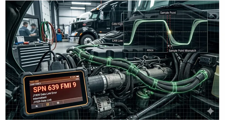
Third time this month the same Class 8 tractor rolled into the bay with the identical story: transmission ECU drops offline for a split second, the engine derates momentarily, and then the truck drives away like nothing happened. Zero active J1939 DTCs. Zero repeatable failure pattern. The technician had already burned the latest J1939 software calibration into the ECM twice, swapped the TCM with a known-good unit, and spent the better part of a shift probing the J1939 harness with a Power Probe looking for opens. The fleet manager’s patience had evaporated. So had mine.
I’ve watched this identical movie play out on job sites from West Texas to Northern Alberta, and in city bus garages from Chicago to St. Louis. The symptoms shift slightly depending on the iron—sometimes it’s the classic SPN 639 FMI 9 (J1939 Data Link Error) that keeps resurrecting itself after you clear it; other times it’s an Allison box that decides to go neutral coast at 65 mph for no apparent reason. But the underlying failure mechanism, once you finally corner it, lives almost entirely outside the boundaries of the J1939 diagnostic flowcharts the OEM gives you.
What you’re hunting is a J1939 bit sampling error. And virtually no one is looking in the right place.
Bit errors on J1939 behave like the auto-immune disorder of heavy-duty vehicle networks. The network turns on itself because the clocks inside the controllers have drifted apart, yet the only feedback you get is “Communications Failure” or “Data Link Error.” The J1939 network never really goes fully down—it hobbles. A CAN message sneaks through, the next one gets mangled. The receiving ECU catches a corrupted bit, bins the entire CAN frame, and waits for a retransmit. Repeat this cycle enough times and the controller finally raises a flag, logging a J1939 communications fault. But by the time you roll the J1939 scan tool out to the truck, the bus has gone silent and the fault is either stored as “intermittent” or has vanished altogether.
This is the phantom J1939 fault that bleeds fleets of real operating capital. We’ve already broken down the financial damage in detail in our analysis of the $4,000/year J1939 phantom fault, and the per-truck math is sobering. Let me show you exactly what’s unfolding at the transistor level, why your J1939 oscilloscope is blind to it, and how to quit treating this as a J1939 software update problem.
What a Bit Sampling Error Actually Is
Let’s confront the uncomfortable truth right up front: 250 kbps J1939 does not mean every J1939 ECU on that twisted pair has a synchronized internal stopwatch agreeing on the precise nanosecond when a “1” flips to a “0.”
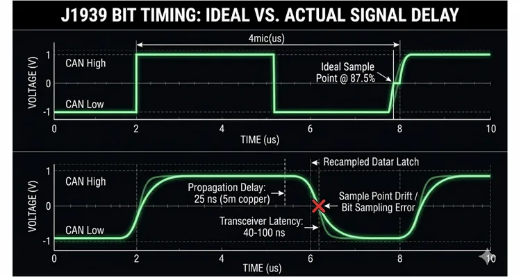
I’m not going to regurgitate the bit timing formula—you can pull the original Bosch CAN 2.0 specification if you need to stare at TSEG1 and TSEG2 register values. What you need to visualize instead is Propagation Delay. At 250k, each bit gets a 4-microsecond window. Node A sits on the firewall; Node B hangs off the frame rail at the rear axle. The voltage edge takes roughly 25 nanoseconds just to sprint down 5 meters of copper. Then that signal smacks into the CAN transceiver, which introduces its own internal propagation lag—anywhere from 40 ns to over 100 ns depending on whose silicon is inside, be it TI, NXP, or another supplier. By the time the distant ECU’s controller actually sees the voltage crossing its threshold, the bit is already 2–3% older than the transmitting node believes it to be.
Now take that same ECU and let it soak in an engine bay where ambient temperatures flirt with 105°C. The ceramic resonator that serves as its heartbeat stops counting microseconds with any real fidelity—it’s approximating. The “J1939 sample point” you selected in a configuration tool stops behaving like a static spreadsheet value and becomes a drifting target. That drift is the root of the entire fight.
So what occurs when two nodes sharing the same bus operate at slightly different J1939 sample points—or when one controller’s internal oscillator has wandered far enough that its clock no longer meshes with the rest of the J1939 network?
You get a J1939 bit sampling error (I refer to it in the field as sample point drift). The receiving node evaluates the bus voltage at the “wrong” sliver of time, catching the differential signal while it’s mid-transition between dominant and recessive. It misreads the bit. A single corrupted bit is sufficient to torpedo the entire frame’s CAN CRC check. The frame gets discarded. No CAN ACK goes back to the sender. The transmitter tries again.
Let this cycle repeat a few thousand times per second during periods of heavy J1939 bus load, and you’ve manufactured an intermittent J1939 communication fault that no amount of J1939 termination resistor inspection will uncover. In fact, many of the common J1939 termination mistakes only serve to temporarily paper over the timing problem rather than eliminating it.
The $4,000/Year Math: Why This Matters More Than You Think
I want to put some concrete numbers against this phenomenon—numbers I’ve pulled directly from fleet maintenance logs and conversations across service counters.
Scenario: A 25-truck Class 8 fleet, each truck accumulating roughly 100,000 miles per year. Three units in the fleet have developed intermittent J1939 communication faults with varying presentations:
- One truck sporadically logs SPN 639 FMI 9, almost always after the powertrain has been under load for 4+ continuous hours.
- Another truck’s Allison transmission intermittently commands a neutral default at highway speeds—a well-documented protective response when the J1939 TCM loses its communication link with the engine ECM over the J1939 backbone.
- The third truck throws a generic “J1939 Data Link Error” that self-clears before any technician can capture a freeze-frame.
The per-truck, per-year financial impact breaks down as follows:
| Cost Category | Conservative Estimate | Realistic Estimate |
| Diagnostic time (tech @ $125/hr, 3–4 hours per incident × 3 incidents) | $1,125 | $1,500 |
| Unnecessary parts replaced (TCM, ECM, J1939 harness segments) | $0 | $800–$1,200 |
| Downtime (lost revenue @ $500/day × 2 days per incident) | $3,000 | $3,000 |
| Mobile service call (one incident per year) | $0 | $400 |
| Annual total per affected truck | $4,125 | $6,100 |
Extrapolate across the fleet: three trucks × a conservative $4,000 minimum each = $12,000/year leaking out of a modest 25-truck operation. Scale up to a 500-truck enterprise, and you’re bleeding $60,000–$80,000 annually in squandered J1939 diagnostic time, unnecessary component swaps, and vehicle downtime—all directed at a fault that a J1939 oscilloscope cannot reveal unless you already know precisely what signature to hunt for.
And the most galling detail: none of those trucks ever contained a defective ECU. The J1939 software updates that were applied didn’t resolve anything because the failure wasn’t in the application code. The failure resided in the physical CAN timing budget between controllers that had never been validated together under real-world thermal and electrical conditions. Fleets that want to truly grasp the financial drain from these misdiagnoses should review our J1939 cable TCO fleet procurement guide for a full accounting.
Why Your Scope Isn’t Showing You the Problem
This is the point where most technicians—and, candidly, a substantial number of engineers—hit a diagnostic wall.
You attach a Picoscope to J1939 CAN H and J1939 CAN L. The differential waveform looks pristine. The voltage swings cleanly between 0V and 2V. Recessive is recessive; dominant is dominant. Every eye diagram you could hope for looks textbook.
But the voltage trace you’re observing is merely what the transmitter placed onto the copper. It reveals nothing about what each J1939 ECU believed it saw when it sampled the bus.
An oscilloscope shows you the transmitter’s output. It cannot expose the moment inside the receiver’s CAN controller when the sample-and-hold circuit latched the bus state. That information lives and dies within the silicon of the CAN controller, gone the instant the bit is processed.
To catch a J1939 bit sampling error, you need either:
- A CAN analyzer capable of logging CAN error frames and identifying J1939 sample point mismatches. I once ran a Vector CANalyzer trace on a truck for 14 continuous hours during a hot-soak test. The error frame counter wasn’t just climbing—it was spiking in lockstep with the engagement cycles of the radiator fan clutch. That’s the level of correlated insight you’ll never extract from a Snap-on J1939 scan tool. You need a tool that captures error passive flags as they happen, not just DTCs long after the event.
- A disciplined, systematic method for verifying J1939 bit timing parameters across every node hanging on the network. This is laborious but non-negotiable. Our CAN bus physical layer testing guide steps through the exact equipment and techniques required for this depth of analysis.
I recall a three-day ordeal on a construction site attempting to troubleshoot a Link-Belt excavator that would randomly ignore joystick commands. The dealer had already replaced the joystick controller, the main ECU, and large sections of the cab harness. Nothing changed. When I eventually connected a CAN analyzer and examined the error frame counter, I saw thousands of bit errors accumulating—specifically on frames that originated from an aftermarket telematics device installed six months prior. That device’s CAN controller had been configured with a sample point at 75%—perfectly acceptable for many industrial CAN networks but entirely marginal for the tighter timing requirements of J1939. Under the temperature swings of a full workday, its oscillator drifted enough to mis-sample bits from the OEM controllers. The telematics unit wasn’t defective; it was simply configured incorrectly for the network it had joined.
Unplugging that single telematics device cleared the fault instantly. Total invoice to the contractor before I showed up: north of $7,000 in parts and labor. The actual fix: disconnect one connector.
The Three Root Causes That Nobody Checks
After years of chasing these failures—both out in the field and inside the J1939 factory floor where we manufacture J1939 cables and harnesses—I’ve distilled J1939 bit sampling errors down to three fundamental mechanisms. Note that “corrupted software” does not appear on this list.
1. Oscillator Tolerance and Temperature Drift
Every CAN controller requires a clock reference—most commonly a crystal oscillator or a less expensive ceramic resonator—to derive its internal bit timing. The SAE J1939-11 standard mandates a nominal bit time of 4.00 μs with a tolerance of 0.05% under idealized bench conditions. But that spec applies at room temperature, with a zero-hour oscillator and no accumulated aging effects.
The real operating environment is far less forgiving. A ceramic resonator embedded in an ECU bolted directly to a hot engine casting will shift its center frequency. That same ECU, cold-soaked overnight in a Minnesota winter at -20°F, will drift the opposite direction. Across years of thermal cycling, the oscillator’s precision gradually erodes.
The net effect: the node’s internal timebase slowly uncouples from the rest of the J1939 network. The J1939 sample point you intended to be at 86% of the bit period at 25°C can effectively migrate to 82% or stretch to 90% once the hardware reaches full operating temperature.
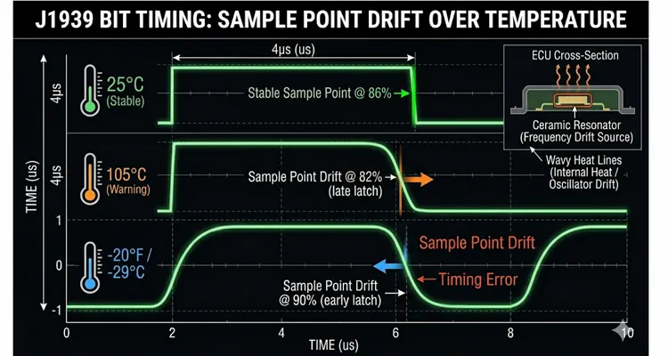
If the drift is severe enough, the controller begins sampling bits during the transitional edges of the waveform—particularly on longer CAN frames where resynchronization accumulates progressively more phase error.
This explains why so many J1939 bit sampling problems are simultaneously temperature-dependent and maddeningly intermittent. The truck runs flawlessly for four hours, the entire powertrain heat-soaks, one ECU’s oscillator slips just beyond the network’s collective tolerance, and a J1939 communication fault materializes. The technician lets the truck cool while retrieving the J1939 scan tool, and by the time diagnostics begin, the fault has vanished. Classic phantom J1939 fault behavior.
2. Mismatched Sample Point Configurations
Not every CAN controller receives the same initialization. Even across OEM ECUs that all carry the “J1939 compliant” label, the actual values programmed into the bit timing registers can differ.
I’ve observed this most frequently in three scenarios:
- A fleet retrofits an aftermarket telematics device or ELD onto the J1939 bus
- A replacement ECU arrives from a different production batch with subtly different firmware defaults
- A third-party controller (hydraulic valve driver, auxiliary I/O module) is integrated without conducting a proper J1939 network validation
The J1939 specification expects the sample point to reside between 75% and 87.5% of the bit time, with 87.5% being the recommended upper bound. But the practical reality is this: CAN controllers from different silicon foundries interpret their bit timing registers differently. The configuration that reads “TSEG1 = 13, TSEG2 = 2” on a Microchip MCP2515 does not produce an identical sample point to the same register values on a TI TCAN4550 or an NXP SJA1000. The resulting sample point can deviate by several percentage points across vendors.
When you mix nodes with sample points at the 75% margin and nodes at the 87.5% margin on a single bus, the 75% node consistently samples earlier. CAN’s built-in resynchronization mechanism—which adjusts phase buffer segments by up to the Synchronization Jump Width (SJW) , typically 1–3 Tq—can absorb minor timing differences under ideal conditions. But introduce a long bus run, significant ringing from improper J1939 termination, or a burst of back-to-back transmissions, and that compensation budget runs dry. The result is bit errors. This is precisely why understanding the proper J1939 backbone and stub length guidelines is essential during any network design or modification.
3. Improper Synchronization Jump Width (SJW) Settings
The SJW parameter governs how aggressively the CAN controller can modify its phase buffer segments during resynchronization events. In practical terms, it’s the “CAN bus timing budget” for absorbing mismatches.
J1939 CAN peripherals typically permit SJW settings between 1 and 3 Tq. A larger SJW increases the node’s tolerance to timing variations from other transmitters but simultaneously heightens the risk that the controller will sample at an inappropriate moment if the adjustment overshoots the ideal window.
The core issue is that SJW is frequently left at the factory default value by engineers who haven’t fully evaluated the implications for their unique J1939 network topology. A default SJW of 1 Tq is conservative but offers minimal flexibility. A network containing 25 ECUs dispersed across 35 meters of twisted pair, subjected to extreme temperature cycling, demands more timing headroom than a default configuration provides.
Yet pushing SJW excessively high (3+ Tq) introduces its own set of problems: the sample point can “hunt” too aggressively during resynchronization, particularly on buses contending with significant J1939 EMI or signal reflections. This produces the exact flavor of sporadic bit errors that resist any attempt at consistent reproduction.
Step-by-Step: How to Actually Find a Bit Sampling Error
If you’ve made it this far, you’ve almost certainly chased a few phantom J1939 faults of your own. The methodology I rely on doesn’t demand a $15,000 Vector toolchain—just a systematic approach.
Step 1: Look Beyond the 60-Ohm Check
You’ve mastered the 60-ohm J1939 check. You’ve performed it more times than you can count. If you’re reading this article, I’m going to assume you’ve already verified J1939 termination and confirmed the expected 2.5V bias—the nominal J1939 CAN High and CAN Low voltage range for a quiescent bus. The one physical measurement that matters for bit sampling and gets overlooked constantly is Capacitance under load.
Break out your LCR meter. Measure the total J1939 bus capacitance. The J1939-11 specification tolerates up to 5 nF per connected node and an additional 500 pF per meter of cable. I’ve personally witnessed aftermarket stub wires—those blue insulation-displacement “vampire tap” connectors—inject an extra 30 nF of capacitance on a stub run of only three feet. That added capacitance doesn’t pull down the DC voltage. It destroys the slew rate. The rising and falling edges of the differential signal round off like a flattened camshaft lobe. The receiver can no longer determine when the bit began because the transition resembles a shallow ramp rather than a crisp step.
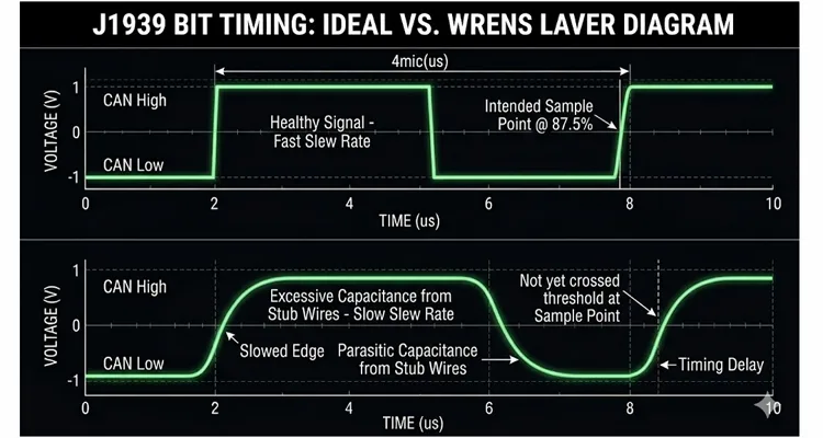
If your J1939 bus capacitance exceeds 60 nF on a 250k J1939 network, you’re not fighting electrical noise—you’re wrestling with a timing delay created by parasitic capacitance masquerading as a J1939 wire harness. Rectify the J1939 physical layer before you waste another hour chasing software ghosts. For a more comprehensive exploration of this diagnostic distinction, refer to our guide on CAN bus diagnostics: multimeter vs. scope.
Step 2: Monitor the CAN Error Counters
This is the step that the overwhelming majority of J1939 technicians bypass entirely. Every CAN controller internally maintains two error counters: the Transmit Error Counter (TEC) and the Receive Error Counter (REC) . Once either counter surpasses 127, the node transitions into “Error Passive” mode. At 255, the controller goes “Bus Off.”
Critically, these counters increment on EVERY bit error—including those that never escalate into a logged J1939 DTC.
You need a J1939 scan tool or a CAN interface capable of querying these counters. On most J1939 ECUs, they’re exposed through diagnostic messages (PGN 65226—the DM1 message for active DTCs—won’t display error counters; you must request DM2 or DM3 data). Hardware such as the DG Technologies DPA 5, Kvaser Leaf Light, or even a basic USB-to-CAN adapter paired with open-source SocketCAN on Linux can retrieve the counter values.
Focus on three indicators:
- Any non-zero CAN error counters appearing on a network that should be pristine
- Counters that increment specifically under certain operating states (fully warmed engine, cold-start conditions, high-vibration regimes)
- A single node exhibiting markedly higher counter values than its neighbors (the prime suspect)
When you observe error counters climbing while the ECU simultaneously reports no active DTCs, you are almost certainly confronting a bit sampling issue or a J1939 physical layer marginality problem.
Step 3: Log Error Frames Over Time
This stage demands slightly more advanced equipment but pays dividends in clarity. A CAN logger that captures CAN error frames will disclose:
- The specific node that transmitted the frame which was ultimately received in error
- The exact error classification (bit error, stuff error, CRC error, form error)
- The precise timestamp of each occurrence
Patterns inevitably surface. In one investigation I conducted, every single error frame appeared within a 30-second window following the moment the engine reached full operating temperature—and every error involved frames traveling from the engine ECM to the transmission TCM. That observation immediately narrowed the problem to two specific ECUs interacting under a defined thermal profile. The transmission ECU’s ceramic resonator was drifting at elevated temperatures, causing it to mis-sample bits originating from the engine controller.
Step 4: Verify Bit Timing Parameters (If You Have Access)
If you represent a J1939 OEM or a fleet with engineering-level access, you can validate the actual bit timing configuration of every node on the network. This is typically performed during development, but it’s equally valuable when chasing stubborn intermittent faults.
The critical J1939 bit timing parameters to confirm for each node are:
| Parameter | J1939-11 Recommendation | Notes |
| J1939 bit rate | 250 kbps ±0.05% | At nominal temperature |
| J1939 sample point | 75–87.5% (aim for 86–87.5%) | Measured from start of bit |
| Synchronization Jump Width (SJW) | 1–3 Tq | Balance between tolerance and stability |
| Propagation segment | Sufficient for longest bus path | Account for 5 ns/m delay + transceiver delays |
| Oscillator type | Crystal (preferred) | Ceramic resonators drift more over temperature |
Absent direct access to ECU firmware, you can frequently infer timing mismatches by correlating which nodes are generating error frames and under what specific operating conditions.
Step 5: Isolate Suspect Nodes
The most pragmatic field remedy for a suspected J1939 bit sampling error is to isolate the suspect node and confirm that the symptom evaporates.
If the vehicle carries a telematics device, ELD, or any form of aftermarket controller tied into the J1939 bus, disconnect it first. I’ve lost count of how many “incurable” J1939 problems I’ve resolved simply by removing a third-party device that had never undergone proper network validation on that specific vehicle platform.
If the fault persists after removing aftermarket hardware, systematically disconnect OEM ECUs one at a time (ignition off, obviously) while monitoring the error counters after each change. The moment the error counters cease incrementing, you’ve located the offending node. For clean, reliable access to the bus during this isolation procedure, a quality breakout harness such as our J1939 9-Pin Pigtail Breakout Cable allows you to monitor traffic and disconnect nodes without backprobing pins or risking connector damage.
One important caveat: J1939 networks with more than two nodes require correct J1939 termination at all times. If you unplug an ECU that hosts one of the two required 120Ω J1939 termination resistors, the bus impedance shifts and you’ll introduce new artifacts that obscure the original fault. Know the physical location of your J1939 termination resistors before you start disconnecting anything. A J1939 voltage drop field test can further identify marginal connections that contribute to timing instability.
Common Mistakes That Make Bit Sampling Problems Worse
Mistake #1: Flashing Software Without Evidence
I’ve observed entire fleets burn through thousands of dollars in software subscription fees simply to keep reflashing J1939 ECUs that were never the source of the fault. If your DTC is SPN 639 FMI 9 or SPN 625 FMI 9 and it’s intermittent, the root cause almost certainly resides outside the application software—at the J1939 physical layer or within the data link layer.
Flashing a revised J1939 calibration does nothing to alter the CAN controller’s bit timing registers. Those registers are typically initialized in low-level firmware or bootloader code that a standard J1939 reprogramming session never touches. You’re modifying the wrong variable entirely. For a thorough explanation of why this strategy fails, read our guide on why software updates won’t fix your J1939 timing problem.
Mistake #2: Replacing ECUs Without Verifying They’re Bad
The “parts cannon” approach is costly and notoriously ineffective against J1939 bit sampling problems. A replacement ECU pulled from the same production batch will share identical oscillator tolerance characteristics and identical bit timing register defaults. You’ll swap the module, the problem may disappear for a few days—simply because the new ECU’s oscillator happens to align slightly better with the network under current conditions—and then the fault returns with the next weather change.
Mistake #3: Adding Ferrite Beads or Filters to the CAN Bus
This is a well-intentioned but hazardous intervention. Adding impedance to the J1939 CAN bus alters its propagation delay, which in turn shifts where the sample point effectively lands for every node on the network. You may inadvertently “resolve” a bit sampling error for one specific node while simultaneously creating fresh timing errors for others.This is a well-intentioned but hazardous intervention. Adding impedance to the J1939 CAN bus alters its propagation delay, which in turn shifts where the sample point effectively lands for every node on the network. You may inadvertently “resolve” a bit sampling error for one specific node while simultaneously creating fresh timing errors for others. This is exactly why a seemingly minor physical-layer violation can have such profound consequences. A 1.8‑meter stub—just 80 centimeters beyond the J1939‑11 limit—creates a 42‑nanosecond reflection that arrives while the CAN controller is sampling the bit. We have a separate deep‑dive that steps through the exact case study, including the oscilloscope waveform that finally exposed it: J1939 Bit Sampling Errors: How 42ns Reflection Distortion Triggers Bus‑Off Events.
I’ve watched technicians wind J1939 CAN H and CAN L conductors around ferrite toroids in an effort to “filter out noise.” Unless you’re referencing a spectrum analyzer that confirms actual J1939 EMI coupling onto the bus, do not do this. The CAN transceivers are already engineered with robust common-mode rejection. The disturbance you’re chasing isn’t external interference—it’s J1939 timing drift. If you genuinely suspect EMI as a contributing factor, our comparison of ferrite cores vs. common-mode chokes for CAN bus will guide you toward the appropriate solution.
Mistake #4: Assuming All 250k J1939 Networks Are Identical
J1939-11 (shielded twisted pair, 250 kbps) and J1939-15 (unshielded twisted pair, 250 kbps) possess different electrical behaviors. J1939-14 (500 kbps) is an entirely separate specification. Even within the boundaries of the same J1939 physical layer specification, different J1939 OEMs deploy distinct topologies, divergent J1939 termination philosophies, and varying node counts.
A bit timing configuration that operates flawlessly on a 3-node J1939 backbone spanning 2 meters of cable can fail intermittently when transplanted onto a 20-node network stretching across 35 meters. The cumulative propagation delay mounts, and the phase error that resynchronization must absorb increases with every added node and every additional meter of J1939 cable. The requirements outlined in our guide to J1939 cable shield, impedance, and jacket selection carry far more weight than most engineers initially appreciate.
How to Confirm You’ve Actually Fixed It
This section separates “I think it’s resolved” from “I have verified it’s resolved.”
1. Monitor Error Counters Over Multiple Drive Cycles
After addressing the root cause—whether by replacing a marginal ECU, removing an incompatible aftermarket component, or correcting a bit timing configuration—reset the error counters and monitor them across at least three to five complete thermal cycles.
A healthy J1939 network should maintain zero active error counters throughout steady-state operation. Occasional errors during startup or shutdown sequences are tolerable; errors accumulating while the vehicle is running are not.
2. Run a Bus Load Test
Use a CAN tool to measure J1939 bus loading under normal driving conditions. J1939 networks should remain below 50% bus load during worst-case messaging bursts. If you’re seeing sustained bus load above 70%, you’re contending with an independent issue—excessive message traffic, an overly aggressive transmit rate, or a node flooding the bus. Elevated J1939 bus load exacerbates bit sampling problems because it reduces the available “quiet time” for resynchronization to stabilize.
3. Temperature-Cycle Validation
If the original fault was temperature-dependent, you must validate the repair under the identical thermal conditions that provoked it. This may entail operating the vehicle until it reaches full operating temperature and then allowing an extended idle period while you monitor error counters.
For fleets experiencing repeatable cold-weather failures, this validation is more challenging but equally necessary. If the problem only materializes at -20°F, you must test at -20°F. A successful room-temperature repair proves exactly nothing.
4. Long-Term Fleet Monitoring
For larger fleets, I strongly advise implementing periodic J1939 health checks as a standard element of preventive maintenance services. A brief 60-second J1939 CAN log captured during routine service can identify climbing error counters long before they trigger a roadside breakdown. The data is available; most fleets simply aren’t collecting it.
The Manufacturing Perspective: Why This Starts on the Factory Floor
I’ve spent more than two decades inside a factory dedicated to producing J1939 cables, J1939 harnesses, and J1939 diagnostic equipment. Our operations are certified to ISO 14001:2015 and IATF 16949:2016, and our products conform to 1298-2 standards. We adhere to 5S management practices within climate-controlled warehouse environments. Every assembly passes through a four-step quality inspection process, and all materials are RoHS compliant with full-plastic designs where appropriate.
Yet here is the essential insight: the build quality of the J1939 cable assembly is merely one component of the larger equation. The J1939 bit sampling problem described throughout this article is, at its core, a system integration issue. It emerges when components sourced from different suppliers—ECUs, J1939 cables, J1939 connectors, and aftermarket peripherals—are joined together in a vehicle without a comprehensive J1939 network validation ever being performed.
We’ve quantified the impact on our J1939 cable assembly line operating under IATF 16949 disciplines. Using a network analyzer, we measured a 1.2% shift in effective sample point between a J1939 cable constructed with a standard PVC jacket and an otherwise identical J1939 cable utilizing a RoHS-compliant TPE jacket when both were stabilized at 85°C. The cause? Dielectric constant variance between jacket materials. The signal velocity within the cable changes. On a 40-meter J1939 backbone, that 1.2% dielectric shift, combined with the 5 ns/m propagation delay we already account for, pushes the network beyond the Synchronization Jump Width margin before the ignition is even switched on. This is precisely why we inquire about J1939 cable length and AWG during any OEM customization discussion. It’s not about increasing the invoice; it’s about guaranteeing that the bits fall cleanly inside the CAN bus timing window.
When we collaborate with J1939 OEMs and equipment builders, we do more than just ship cable assemblies. We ask the following questions:
- What is the intended J1939 network topology? (Total node count, J1939 bus length, J1939 stub length)
- Which CAN transceivers populate the various ECUs? (Propagation delay characteristics vary by supplier)
- What is the full operating temperature envelope? (Oscillator drift is temperature-driven)
- Will any third-party devices be connected to the J1939 bus after the vehicle leaves the factory?
These questions carry real weight. They represent the dividing line between a J1939 network that functions on paper and one that functions in the field. Our OEM engineer checklist for EMI-hardened diagnostic cables offers a solid foundation for any new vehicle integration effort.
Frequently Asked Questions
Q1: What exactly is a J1939 bit sampling error?
A J1939 bit sampling error happens when a CAN controller evaluates the differential bus voltage during the transitional period between dominant and recessive states. Rather than registering a definitive “1” or “0,” the controller encounters an ambiguous intermediate voltage and may misclassify the bit. The affected CAN frame fails its CRC verification and is discarded. These errors accumulate silently until they eventually manifest as J1939 communication faults.
Q2: Why don’t my DTCs point to a bit sampling problem?
J1939 fault codes including SPN 639 FMI 9 and SPN 625 FMI 9 signal that expected communication was interrupted or that received data was invalid. The ECU recognizes that messages failed to arrive, but it possesses no diagnostic visibility into why they failed. The bit sampling error occurs within the CAN controller hardware, beneath the application layer that generates J1939 DTCs. The symptom gets recorded; the underlying mechanism remains hidden.
Q3: Can a bad J1939 cable cause a sample point error?
No. A J1939 cable cannot alter the programmed sample point—that value resides in firmware. However, a J1939 cable exhibiting excessive capacitance or a degraded shield drain connection can effectively delay the arrival of the transmitter’s signal edge. If the signal rise time stretches to 200 ns rather than the expected 50 ns, the receiver’s internal comparator (threshold typically 0.7V differential) triggers later. The ECU’s sample point remains fixed at 87.5%, but the bit’s leading edge reaches the controller “late.” To the CAN controller, this delay is indistinguishable from clock drift. This is why our J1939 harnesses undergo 100% continuity and hipot testing—it’s the only method to safeguard the timing budget at the physical level. For additional detail on cable performance criteria, refer to our guide on J1939 cable shield, impedance, and jacket specifications.
Q4: How do I check if my CAN tool can read error counters?
Numerous professional J1939 scan tools (Noregon JPRO, Cummins INSITE, CAT ET) can retrieve CAN error counters through diagnostic messaging, though the specific procedure varies by tool and ECU vendor. If you’re using a generic J1939 adapter with open-source utilities, search for commands that interrogate the CAN controller status registers. Under Linux with SocketCAN, the command ip -details -statistics link show can0 will output the current error counters.
Q5: Is this problem more common on 250k or 500k J1939 networks?
Both are susceptible. The underlying physics are identical; the bit time simply shrinks to 2 μs at 500k. Shorter bit windows translate to reduced timing error margin, so configurations that operate marginally at 250k J1939 are more likely to fail at 500k J1939. The J1939-14 (500k) specification is more recent and less broadly fielded, but the fundamental principles apply uniformly.
Q6: Can I fix a bit sampling error by adjusting termination resistors?
No. J1939 termination influences signal integrity—reflections and ringing—but does not alter the sample point timing. If the issue is strictly a sample point mismatch, modifying termination will not resolve it and may actually compound the problem if you deviate from the mandated 60Ω total impedance. To fully appreciate the financial consequences of incorrect termination, review our analysis of J1939 termination mistakes and ECU repair costs.
Q7: What’s the difference between a bit error and a stuff error?
A bit error signifies that the receiver detected a bit value inconsistent with what the transmitter sent (determined by the CAN controller’s simultaneous monitoring of its own transmission). A stuff error indicates that the bit stuffing rule—no more than five consecutive identical bits—was violated. Both can stem from sampling errors, but stuff errors are especially prevalent when a node mis-samples multiple consecutive bits in a single frame.
Q8: Why does the problem only happen when the truck is hot?
Temperature directly influences oscillator frequency. As an ECU absorbs heat, the center frequency of its crystal or ceramic resonator shifts incrementally. If the cumulative shift pushes the effective sample point beyond the tolerance envelope of the remaining nodes on the bus, bit errors commence. Once the truck cools, the oscillator drifts back toward nominal and the fault vanishes—until the next extended hot run.
Q9: Should I replace the ECU or try to reconfigure it?
If you possess access to the ECU’s CAN bit timing parameters (generally through engineering-level configuration tools), adjusting to a more conservative sample point (nearer to 87.5%) and an appropriate SJW value may eliminate the J1939 issue. Without that access, and if the ECU is definitively the source, replacing it with a unit from a separate production batch might provide temporary relief—but there is no guarantee. The root condition is usually a design-level timing margin problem, not a component defect.
Q10: How do I prevent bit sampling problems when adding aftermarket devices to J1939?
The most reliable practice is to validate any aftermarket device on the target J1939 vehicle network prior to fleet-wide deployment. This entails connecting the device, monitoring CAN error counters across complete thermal cycles, and verifying that no new error frames emerge. If the device supplier cannot furnish its CAN bit timing parameters (sample point, SJW, oscillator tolerance), regard the device as a high-risk addition. Telematics and ELD manufacturers are gradually improving their transparency, but the responsibility for J1939 validation still rests squarely with the fleet operator.
What This Means for Your Operation
J1939 bit sampling errors are genuine, they are costly, and they remain almost entirely opaque to conventional J1939 diagnostic procedures. They impersonate “defective ECUs,” “software anomalies,” and “J1939 wiring problems.” They drain thousands of dollars per truck annually in squandered J1939 diagnostic time and unnecessary component replacements.
The remedy is not another round of J1939 software updates. The remedy lies in comprehending what is actually occurring at the CAN bit level, learning to monitor error counters effectively, and exercising the discipline to isolate the root cause rather than unleashing the parts cannon.
If you are an OEM or equipment builder confronting persistent J1939 communication issues, or if you’re manufacturing J1939 harnesses and must ensure your J1939 cables are not eroding the timing margin, we can assist with the J1939 physical layer portion of the challenge. Our engineering group understands that a J1939 cable is more than copper—it’s a component of the J1939 network’s timing budget.
Reach out through our Contact page for J1939 engineering support or OEM customization inquiries. For a faster response on technical questions, you’re welcome to connect via WhatsApp.
Contact Page: https://obd-cable.com/contact/
Stop chasing phantom J1939 faults with J1939 software updates. The issue resides in the J1939 timing—and now you possess the method to pinpoint it.
