

By the CARSUN Engineering Team | 20+ Years in Heavy‑Duty Diagnostics and Cable Manufacturing
Few scenarios paralyze a service bay as thoroughly as a SAE J1939 network that has decided to misbehave. The ECM broadcasts an “Engine Speed Source” error. The ABS module insists it has lost contact with the Transmission. Meanwhile, the Instrument Cluster—a $1,200 assembly—sits frozen with a blank tachometer. I have stood beside technicians who immediately reached for a laptop to reflash firmware, long before they bothered to pick up a multimeter. That instinct is expensive. Across twenty years of crawling under heavy equipment and overseeing a factory that produces diagnostic cables by the thousand, the lesson burned into my muscle memory is this: the culprit is rarely software. It is copper. A strand of wire rubbed raw against a frame rail. A termination resistor fatigued by half a million miles of vibration. Or a shield drain that only makes contact while the engine block is still cold. The skill that separates a one‑visit repair from an expensive parts‑cannon disaster is knowing precisely where to place the meter leads—and, equally crucial, recognizing the moment you must ignore the meter and trust the waveform unfolding on a scope. Let us work through the process. No academic detours—only the sequence that moves trucks back out the gate.
When the Network Goes Silent: Recognizing Physical Layer Failure
A J1939 data link seldom announces its demise with a single, well‑mannered fault code. It stutters. It floods the log with contradictory complaints. Then it falls mute. If you prefer a methodical triage routine that catches these failures before they consume half your afternoon, we have consolidated a field‑hardened 20‑minute J1939 data link diagnostic checklist that steps through the exact resistance and voltage checks.
I recall a 2017 Western Star 5700XE that coasted in with a fully illuminated dash but no engine RPM displayed. The instrument cluster had power, yet the J1939 messages carrying the tachometer value never materialized. The fault memory was a catalog of desperation: Loss of Communication with ECM, Loss of Communication with ABS, Intermittent CAN Bus Error. A technician operating on guesswork would have replaced the cluster, then the ECM, then the entire harness. Instead, we reached for a meter.
The pattern is now etched in my brain: when multiple ECUs—engine, transmission, ABS, and cluster—simultaneously report communication loss, the target is not a solitary bad module. The failure resides in the physical layer. The CAN controllers inside each module remain functional. The transceivers are attempting to exchange data. But the twisted copper bridging them has been sabotaged—by corrosion, a chafe point, or a poorly executed splice. For a more granular look at what this diagnostic confusion actually costs a fleet operation, examine our breakdown of a $4,000/year J1939 phantom fault that shops repeatedly attributed to software glitches.
Additional warning signs I have cataloged over the years:
- Intermittent “Bus Off” events that clear with a key cycle, only to resurface later
- A specific ECU repeatedly dropping off the network and rejoining at unpredictable intervals
- Diagnostic scan tools that establish a handshake, then abruptly lose communication
- A vehicle that operates flawlessly for twenty minutes, then inexplicably derates and recovers
- Active fault codes that explicitly cite “J1939 Data Link” or “CAN Bus Error“
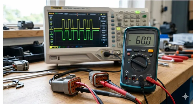
If any of this describes the truck in your bay, close the laptop, disregard the software update prompt, and retrieve your multimeter. We begin with the most overlooked diagnostic maneuver in heavy‑duty repair: the 60‑ohm test.
The 60‑Ohm Question: What Your Multimeter Is Actually Measuring
Set aside the parallel‑resistance equation you memorized in trade school. Here is the practical translation of a 60‑ohm reading in a real shop with a warm engine and a service writer pacing the floor. You place your probes on Pins C and D of the 9‑pin Deutsch diagnostic connector. A reading of 60 ohms allows you to exhale. A reading of 120 ohms triggers a groan, because you already know one end of that truck has consumed a termination resistor—and it is invariably lodged behind the DEF dosing tank or wedged atop the transmission bellhousing.
The physics carries more weight than most technicians appreciate. If you are contending with a J1939‑15 unshielded backbone and a stub has crept to 3.1 meters—a mere tenth of a meter beyond the 3‑meter specification—the resulting impedance mismatch spawns a 42‑nanosecond echo. That reflection races backward and collides with the subsequent bit. Your meter registers a placid 60 ohms of DC resistance, but that reading conceals the AC impedance anomaly at the compromised splice. Electrically, the network appears “connected” to the meter, yet the CAN controllers are drowning in signal reflections they cannot resolve. That discrepancy defines the chasm between a passing static test and a legitimate repair. For the full engineering treatment of backbone architecture and stub length boundaries that withstand real‑world vibration, consult our J1939 backbone and stub length guide.
Where J1939 Hides Its Termination Resistors
Factory wiring diagrams offer a useful starting point, but they do not always mirror what the assembly line actually delivered. On a Paccar MX engine, the second 120‑ohm resistor is not mounted at the ECM—it is concealed within the Aftertreatment Control Module connector harness, adjacent to the SCR catalyst. On a Detroit DD15, one termination resides inside the CPC module near the firewall bulkhead. On earlier Freightliner chassis, the Bulkhead Module houses internal termination that engages only after the connector is fully seated and locked. The essential takeaway: do not place blind trust in a generic diagram. Learn where each vehicle platform stashes its resistors. If you are tallying the financial toll of termination and stub length oversights, we have computed the precise $4,000/year phantom fault cost that fleets absorb from these mistakes.
The Right Way to Measure J1939 Resistance
This measurement demands a disciplined approach, and I have observed technicians commit every conceivable misstep.
Step one: Battery disconnect. Not merely ignition off—physically remove the battery ground cable. Keep‑alive circuits within certain ECUs can sustain voltage at the CAN transceivers for several minutes after key‑off, or indefinitely if those circuits tap constant battery power. I once destroyed the input protection on a Fluke meter while probing a Volvo that was back‑feeding 5 volts through a dormant transceiver. The meter endured. My confidence in my own diagnostic rigor did not.
Step two: Locate your test point. The most accessible entry is the 9‑pin Deutsch diagnostic connector inside the cab. Pin C serves CAN_H (typically a yellow conductor), and Pin D serves CAN_L (typically green). While positioned there, verify Pin E (Shield). If you measure 120 ohms between Pin C and Pin E, the issue is not a corrupted data line—it is a chafed wire permitting the shield to short against the CAN_H conductor. Should the diagnostic connector be damaged or absent, you may probe directly at any ECU connector, but you must have the specific pinout for that module. For a complete visual reference of the 9‑pin Deutsch layout and its common failure modes, review our 9‑pin Deutsch connector diagnostic fix. The standard J1939/13 diagnostic connector pinout is a laminated reference I keep inside my meter case for precisely this scenario.
Step three: Meter setup. Configure your multimeter for resistance (Ω) with auto‑range enabled if available. Apply firm probe pressure to Pins C and D.
Step four: Interpret the reading. A healthy J1939 network with both terminations intact should display between 55 and 65 ohms. Variations in ambient temperature, cable length, and resistor tolerance will cause minor drift. Do not become unsettled by a reading of 58 ohms or 62 ohms.
Interpreting Your Resistance Reading
| Reading | What It Means | Next Step |
| Next Step | Both terminations accounted for, backbone intact | Advance to voltage checks; physical layer is likely sound |
| ~120 Ω | One termination missing or open circuit to one bus end | Locate the absent termination resistor |
| ~40 Ω | A third termination is active (someone installed an extra, or a module’s internal termination is erroneously enabled) | Identify and remove the superfluous resistor |
| <30 Ω | Short between CAN_H and CAN_L | Disconnect ECUs sequentially to isolate the short |
| >10 kΩ or OL | Open circuit somewhere within the backbone | Trace wiring for fractures; inspect bulkhead connectors |
| Fluctuating | Intermittent connection | Execute a wiggle test while observing the meter |
One additional point worth retaining: on J1939‑15 unshielded networks, the permissible stub length extends to 3 meters and the node count contracts to 10, yet the termination requirements remain unchanged—two 120‑ohm resistors positioned at the physical extremes of the backbone.
When 60 Ohms Is a False Positive
I have observed countless technicians walk directly into this snare. They record 60 ohms, pronounce the network electrically intact, and proceed to swap ECUs. One week later, the same truck returns with the identical intermittent complaint. For a sobering examination of the financial consequences this trap generates, read our analysis of J1939 termination mistakes that cost $3,000 in ECU repairs.
A static resistance reading merely confirms the bus is neither shorted nor open. It reveals nothing about signal quality. It cannot visualize reflections ricocheting from an impedance mismatch. It cannot detect noise coupling from a poorly routed alternator cable. And it cannot identify a transceiver that is too weak to drive the bus to the required dominant voltage level. To assess those conditions, you must examine the actual waveform.
When the Meter Lies: Why You Still Need a Scope
The 42‑Nanosecond Echo That Kills Communication
J1939 transmits at 250 kbps, allocating each bit a comfortable 4 microseconds of airtime. That margin appears generous until you introduce an impedance mismatch—a splice constructed with mismatched wire gauge, or a stub that has been stretched to 1.3 meters on a J1939‑11 backbone that specifies 1 meter maximum.
When a dominant bit encounters that impedance discontinuity, a portion of the signal reverses direction. That reflection travels back along the conductor and reaches the receiver approximately 42 nanoseconds later, coinciding with the moment the receiver attempts to sample the bit value. The CAN controller encounters a distorted voltage level, cannot reliably determine whether the bit is dominant or recessive, increments its error counter, and ultimately transitions to Bus‑Off to safeguard the network. This is the precise failure cascade we unpack in our detailed exploration of J1939 bit sampling errors and 42‑nanosecond reflection distortion. To fully grasp this mechanism, it helps to possess a working understanding of CAN bus differential signaling and how physical layer degradation compromises the recessive‑to‑dominant transitions that J1939 depends upon.
Your multimeter is entirely oblivious to this phenomenon. It measures only DC resistance. The bus could be a churning ocean of signal reflections, and your meter would continue to display a pristine 60 ohms.
I absorbed this lesson on a refuse truck that intermittently lost its transmission controller every 20 to 40 minutes. Resistance checked out at 60 ohms. Voltages appeared normal. We replaced the TCM on two separate occasions. At last, we attached a scope and discovered the stub feeding the transmission controller extended nearly 2 meters—someone had lengthened it with a segment of non‑twisted primary wire to accommodate a replacement Deutsch connector. The reflection pattern was unmistakable. Once witnessed, it is never forgotten. This very scenario—a waveform that appears clean while an ECU misinterprets bits—is examined exhaustively in our guide to the $4,000/year J1939 bit sampling phantom fault.
Heat and Vibration: The Scope Reveals What the Meter Misses
I encountered another truck whose J1939 bus appeared immaculate when cold. Yet twenty minutes into a road test, the waveform deteriorated into the visual equivalent of a seismograph during an earthquake. The fault was not a defective ECU. The transmission bulkhead connector was expanding with heat, just enough to interrupt continuity on the shield drain wire. The meter could not capture the event because the connection would momentarily re‑establish itself—sufficient to deceive a brief resistance check. The scope, however, recorded the intermittent common‑mode voltage drift that manifested exclusively once the drivetrain reached operating temperature. That distinction captures the difference between an instrument that measures and one that truly observes. For an exhaustive comparison of when to rely on each tool, refer to our CAN bus diagnostics: multimeter vs. scope guide.
Setting Up the Scope for J1939 Waveform Capture
If you have never connected a scope to a CAN bus, the field‑tested configuration below will serve you well.
Channel assignments: Connect Channel A to CAN_H (Pin C) and Channel B to CAN_L (Pin D). If you possess a differential probe, employ it—it subtracts common‑mode interference and shields your scope inputs. Absent a differential probe, use two standard probes with both ground leads secured to a clean chassis ground point near the diagnostic connector.
Timebase: Configure for 50–100 µs/div to observe several CAN frames simultaneously. For detailed bit‑level inspection, reduce to 10–20 µs/div.
Voltage range: Set both channels to 2 V/div with a 0 V reference positioned near the lower edge of the display. A healthy CAN_H signal transitions from approximately 2.5 V recessive to 3.5 V dominant. CAN_L mirrors this behavior, moving from 2.5 V recessive down to roughly 1.5 V dominant. For a comprehensive reference on normal voltage ranges for both CAN High and CAN Low—including what your DMM should report versus what the scope reveals—consult our J1939 voltage levels guide.
Trigger: Configure to trigger on Channel A, falling edge, at approximately 2.0 V. This setting captures the recessive‑to‑dominant transition.
Sample rate: Use a minimum of 2 MS/s—ideally 5 MS/s or higher—to resolve signal edges with adequate fidelity.
What a Healthy J1939 Waveform Looks Like
A correct J1939 waveform demonstrates several non‑negotiable attributes:
- Differential symmetry: CAN_H and CAN_L must appear as near‑perfect mirror reflections. As CAN_H ascends, CAN_L descends.
- Sharp transitions: The signal edges should resemble vertical cliffs, not gently sloping hills.
- Clean recessive level: Both conductors should stabilize at approximately 2.5 V during idle periods.
- Consistent amplitude: The differential voltage (CAN_H minus CAN_L) should measure roughly 2 V during dominant bits and approach 0 V during recessive bits.
- No ringing: The signal must not oscillate after transitions. If you detect small fangs or ripples trailing each edge, an impedance mismatch exists somewhere along the backbone.
Decoding the Signal: Beyond the Waveform
Most contemporary scopes—including entry‑level USB‑powered units—incorporate CAN decoding functionality. Enable serial decode, set the baud rate to 250 kbps, and the scope translates the raw bitstream into intelligible J1939 messages.
This is the stage where you perceive what the network is genuinely attempting to communicate. Capture 10–20 seconds of bus traffic, export the decoded information as a CSV file, and analyze which ECUs are transmitting and which messages receive acknowledgment. This technique proves invaluable for detecting a module that is babbling—inundating the bus with redundant transmissions and obstructing legitimate communication.
Waveform Diagnostics: What You’re Seeing and What to Do About It
| Phenomenon | What It Means in Human Terms | The Physical Fix |
| Edges look like hills, not cliffs | Someone inserted a segment of untwisted trailer wire to lengthen a stub. | Remove it. Install proper shielded twisted‑pair of identical AWG. |
| Little fangs trailing each edge | A connector along the backbone is not fully seated. | Firmly press the 3‑pin connector at the firewall pass‑through until it latches. |
| Signals crossing, no mirror | CAN_H and CAN_L are shorted together—frequently at a rub location on a bracket. | Locate the chafe, restore insulation, and secure the harness away from metal contact. |
| One line stuck at 0 V or 5 V | That specific conductor is shorted directly to ground or battery positive. | Trace the harness; inspect near exhaust shielding where heat can melt insulation. |
| Recessive voltage drifting upward | The shield is grounded at both ends, producing a ground loop, or a transceiver is failing. | Sever the shield drain at one end; ground exclusively at the cab side. |
| Both lines stuck at 2.5 V | The bus is silent. Either an open circuit exists, or all transceivers are in sleep mode. | Verify backbone continuity; confirm ignition‑switched power reaches each ECU. |
I maintain a directory of known‑good waveform captures from prevalent vehicle platforms on my laptop. When I am uncertain whether a given trace is normal or pathological, I retrieve a reference capture from the same vehicle family. That practice has preserved more hours of diagnostic clarity than any other single habit.
The Five‑Minute Physical Layer Checklist
Before you invest hours hunting an elusive fault, execute the following sequence. With repetition, it consumes less than five minutes on any vehicle that presents with a J1939 communication complaint. For the complete physical layer testing protocol that has spared our customers thousands in diagnostic charges, consult our CAN bus physical layer testing guide.
Step 1: Power Down, Measure Resistance
Battery disconnected. Meter configured for ohms. Probe Pins C and D. Target 55–65 ohms.
If not: Locate the absent termination. On the majority of trucks, one termination resides in the cab (often adjacent to the instrument cluster or at the diagnostic connector), while the other is situated under the hood. However, recall the platform exceptions: Paccar MX conceals one termination within the aftertreatment harness. Detroit CPC modules contain internal termination. Certain ECUs activate termination only after the connector is fully locked—never presume that a missing external resistor indicates an unterminated network.
Step 2: Resistance to Ground and Power
With the meter still set to ohms, measure CAN_H to chassis ground, followed by CAN_L to chassis ground. Both must read open circuit (OL or >10 kΩ). A reading below 1 kΩ signals a partial short to ground. Next, measure to battery positive (ignition off). Again, the circuit must read open. A short to power or ground will displace the bus voltage from its specified operating envelope. For a 90‑second field test that exposes the voltage drop abnormalities most shops overlook, review our J1939 voltage drop diagnostic.
Step 3: Power Up, Measure Voltage
Reconnect the battery. Switch ignition on (engine off). Configure meter for DC volts. Measure CAN_H to ground: anticipate 2.3–2.7 V. Measure CAN_L to ground: anticipate 2.3–2.7 V. Measure differential voltage between CAN_H and CAN_L: anticipate 0 V when the bus is idle. If you encounter 5 V on one conductor and 0 V on the other, a short to power or ground is present.
Step 4: Connect the Scope
If Steps 1–3 pass but the issue endures, the scope becomes necessary. Search for the mirror pattern, crisp edges, and correct voltage amplitudes. Capture 10 seconds of bus traffic and decode the stream. Monitor for unresponsive modules, endlessly repeating messages, or error frames.
Step 5: Isolate the Culprit
Should the waveform appear degraded, disconnect ECUs individually while observing the scope. When the waveform abruptly restores to a clean state, you have pinpointed the module or stub that is burdening the bus. This technique excels at locating a transceiver whose failure mode drags the recessive voltage outside specification.
Step 6: The Wiggle Test
Simple in concept, yet remarkably effective. With the scope active and displaying a waveform, methodically manipulate the wiring harness at connector housings, bulkhead pass‑throughs, and any location where the harness undergoes sharp bending. Observe the scope display for glitches, dropouts, or alterations in waveform morphology. I have uncovered more intermittent opens using this method than any other.
Step 7: Verify the Fix
Following any repair—whether replacing a termination resistor, mending a splice, or exchanging a transceiver—repeat the complete checklist. Resistance must return to 60 ohms. Voltages must reside within nominal ranges. The waveform must exhibit pristine clarity. Only then should you clear the codes and proceed with a road test.
Five Mistakes That Send You Down the Wrong Path
I have committed each of these errors at least once. Spare yourself the same frustration.
Mistake 1: Measuring Resistance with Power Applied
This represents the most prevalent misstep I witness. Even with ignition switched off, certain ECUs maintain power to their CAN transceivers for several minutes—or indefinitely if wired to constant battery voltage. Measuring resistance while voltage remains on the bus produces meaningless readings and may harm your meter. Always remove the battery ground cable first.
Mistake 2: Assuming 60 Ohms Applies Anywhere on the Bus
You cannot accurately measure termination resistance from the midpoint of a stub. Probing at a stub connector or any location not situated between the two terminations will yield a value other than 60 ohms. The 60‑ohm reading emerges only when you measure across the entire backbone with both terminations in the circuit. Always measure at the diagnostic connector; it is positioned at the electrical midpoint for precisely this purpose.
Mistake 3: Ignoring the Shield
J1939‑11 mandates shielded twisted‑pair cable because heavy‑duty operating conditions are electrically hostile. Alternators, starter motors, and solenoids produce electromagnetic interference that couples onto the data conductors and corrupts J1939 messages. The shield must be grounded at exactly one location—typically the cab end. Grounding it at both ends generates a ground loop that injects noise rather than suppressing it. Leaving the shield floating provides no protection whatsoever. I have resolved “mystery” intermittent communication failures simply by correctly terminating the shield drain. For a thorough examination of shield, impedance, and jacket specifications that endure real‑world abuse, refer to our J1939 cable specification guide.
Mistake 4: Adding a Termination Resistor to “Fix” a 40‑Ohm Reading
A customer once proudly reported that he had resolved his J1939 issues by installing a third termination resistor because his meter displayed 40 ohms. That 40‑ohm reading was informing him that a third termination already existed—likely a module with internal termination mistakenly left enabled. Introducing a fourth resistor further reduced bus impedance, overloading the transceivers. The network limped along for several weeks before failing entirely. Do not add resistors. Determine why the existing termination configuration is incorrect. For the wiring diagram and CAN High/CAN Low reference that assists in tracing these errors, consult our J1939 wiring diagram guide.
Mistake 5: Trusting a Clean Waveform Without Checking Stub Lengths
You may encounter a pristine waveform at the diagnostic connector while communication difficulties persist at the far end of the bus. If a stub exceeds the specified maximum—1 meter for J1939‑11, 3 meters for J1939‑15—signal reflections from that stub will disrupt communication for the module attached to that stub while leaving the remainder of the bus appearing undisturbed. When an individual module misbehaves yet the backbone appears healthy, measure the physical distance from that module to the backbone splice point. I have discovered stubs originally designed to be 0.5 meters that were “extended” to 2 meters using whatever wire happened to be within reach.
How to Know You’ve Actually Fixed It
The Post‑Repair Validation Protocol
Clearing the fault codes and observing that the check engine lamp remains extinguished is insufficient. I have been misled by this outcome more times than I can tally. The fault was intermittent, it disappeared for three days, and the customer telephoned on the fourth morning.
The validation sequence I now apply to every J1939 physical layer repair is as follows:
Immediate post‑repair checks:
- Resistance across Pins C and D: 60 ohms ±5
- CAN_H and CAN_L voltage to ground: 2.3–2.7 V each
- Scope capture: Clean mirror waveform, sharp edges, absence of ringing
- Resistance to ground and power: Open circuit on both conductors
Communication verification:
5. Scan tool establishes and sustains connection without interruption
6. All expected ECUs reply to a network scan
7. No “Loss of Communication” codes set during initial power‑up
Road test verification:
8. Minimum 20‑minute road test with scan tool logging active
9. Monitor for any “Bus Off” events or error frame counts that increase
10. Confirm that previously intermittent symptoms do not reappear
Long‑term validation:
11. If the vehicle history includes intermittent failures that surfaced every few days or weeks, I advise a follow‑up scope capture after 50–100 hours of operation. This precaution may appear excessive, but for fleet assets that cannot accommodate unscheduled downtime, it constitutes inexpensive insurance.
A Field‑Proven Success Story
During the past year, a fleet manager contacted us regarding a J1939 network that was confounding his technicians. Six ECUs operated on a 250 kbps backbone, and the transmission controller would vanish from the bus at 20‑ to 40‑minute intervals. They had replaced the TCM twice and performed three software updates. Resistance consistently measured 60 ohms.
We requested that he connect a scope to the bus. His findings were definitive: a clean waveform appeared at the diagnostic connector, but probing at the TCM connector revealed pronounced ringing on the falling edges. The stub feeding the TCM had been lengthened with a section of non‑twisted primary wire to accommodate a replacement Deutsch connector, generating a sharp impedance discontinuity. Each time the TCM transmitted, the reflections from that discontinuity corrupted its own acknowledgment frame, eventually forcing it into Bus‑Off mode.
He replaced the stub with proper twisted‑pair cable, trimmed to the specified length. The problem ceased. No software update. No module replacement. Only copper functioning as copper was intended to function.
Related Products from CARSUN
Note: The following sections describe products we manufacture for OEM and engineering clients. We are a factory direct supplier, not a retailer. Every assembly is custom‑configured to your precise requirements.
J1939 9‑Pin Deutsch Cables
When we manufacture a J1939 cable within our facility, the 4‑step QC procedure is not promotional material. It is the reason you will not encounter inexplicable 40‑ohm readings on a freshly unpacked harness. Step 3—the impedance sweep test at 250 kHz—is a verification that the majority of imported cables omit entirely. They confirm continuity and consider the job finished. We validate Characteristic Impedance because even a 5‑ohm deviation introduces the identical reflection pattern that this article has trained you to identify. That distinction separates a cable that merely connects from one that genuinely troubleshoots. For OEMs overseeing validation fleets, that distinction separates a clean data log from a phantom derate that halts development. For a complete comparison of Deutsch DT and HD series connectors utilized in these assemblies, consult our J1939 connector types guide.
Our J1939 9‑pin Deutsch cable assemblies are fabricated to SAE J1939‑11 standards using 18 AWG or 20 AWG shielded twisted‑pair conductors. Each cable undergoes 100% continuity testing and resistance verification before departing our climate‑controlled warehouse.
We offer:
- Standard and custom lengths (0.5m to 10m+)
- Straight and right‑angle Deutsch DT connectors
- OEM branding and custom jacket colors
- RoHS‑compliant materials with full‑plastic overmold construction
J1939 Y‑Splitter and Breakout Cables
For diagnostic access that preserves backbone continuity, our Y‑splitter cables enable connection of a scan tool while the network remains fully operational. The breakout cable variant provides dedicated test points for CAN_H, CAN_L, and shield, streamlining oscilloscope attachment.
J1708 to J1939 Diagnostic Adapters
In mixed‑fleet service environments where J1708 (6‑pin Deutsch) and J1939 (9‑pin Deutsch) protocols coexist, our adapter cables deliver uninterrupted connectivity with accurate pin‑mapping to prevent diagnostic errors. For context on why J1708 diagnostics continue to affect your operational bottom line, see our J1708 legacy protocol support guide.
Custom OEM Cable Solutions
As an ISO 9001, ISO 14001, and IATF 16949 certified manufacturer with over 20 years of direct factory experience, we focus on custom diagnostic cable solutions for equipment builders and large‑scale fleet operators. Our engineering personnel work directly from your specifications to create cables that satisfy your exact electrical and mechanical criteria. You may verify our ISO 9001:2015 certification and our recent IATF 16949:2016 certification milestone.
Customization options include:
- Logo and brand imprinting
- Cable length and jacket coloration
- Wire gauge (AWG) selection
- Connector orientation and keying configuration
- Shielding configuration and drain wire placement
Every product is manufactured under 5S management discipline and passes comprehensive testing prior to shipment:
- Incoming material inspection (RoHS compliance verification)
- In‑process continuity testing
- Final assembly functional verification
- Pre‑shipment quality audit
We hold UL, CE, and REACH certifications across our product portfolio.
For engineering support, OEM customization inquiries, or technical consultation regarding J1939 physical layer diagnostics, our team is accessible through the contact channels listed below.
Frequently Asked Questions
Q: Why is J1939 termination resistance 120 ohms specifically?
A: The 120‑ohm value is chosen to correspond with the characteristic impedance of the twisted‑pair cable prescribed in SAE J1939‑11. Impedance matching attenuates signal reflections at the bus extremities. A mismatched termination returns energy along the cable, where it collides with subsequent bits and induces sampling errors. This concept mirrors the principles applied in high‑frequency transmission lines and RF antenna systems.
Q: Can I use an off‑the‑shelf 120‑ohm resistor from an electronics supplier as a termination?
A: Electrically, yes—as a temporary measure. However, automotive termination resistors are rated for 0.25 W minimum and are packaged to endure vibration, thermal cycling, and humidity. A conventional carbon‑film resistor will function electrically but is prone to premature failure when installed in an engine compartment. We advise using resistors expressly engineered for automotive CAN bus termination.
Q: What distinguishes J1939‑11 from J1939‑15 at the physical level?
A: J1939‑11 utilizes shielded twisted‑pair cable, permits a maximum backbone length of 40 meters, restricts stub length to 1 meter, and accommodates up to 30 nodes. J1939‑15 employs unshielded twisted‑pair (UTP) with the identical backbone length but allows stub lengths up to 3 meters and supports up to 10 nodes. Termination requirements—two 120‑ohm resistors at the bus ends—are identical for both specifications.
Q: My meter shows 120 ohms, but I can only locate one physical termination resistor. Where is the second one?
A: This situation is routine. One termination is frequently integrated inside an ECU—commonly the Engine Control Module, Transmission Control Module, or ABS module—and is engaged by an internal jumper or circuit logic. On certain platforms, termination becomes active only when the ECU connector is fully locked. Consult the vehicle‑specific wiring diagram to determine which modules house internal termination. Additionally, note that some modules enable termination solely when powered, which explains why you must disconnect the battery prior to measuring.
Q: Specifically, where is the termination resistor on a Paccar MX engine?
A: On Paccar MX platforms, the second 120‑ohm termination resistor is situated inside the Aftertreatment Control Module connector harness, adjacent to the SCR catalyst—not at the ECM as many generic diagrams indicate. If you register 120 ohms at the diagnostic connector and cannot locate the absent termination, inspect the aftertreatment harness thoroughly.
Q: How do I identify CAN_H and CAN_L on a 9‑pin Deutsch diagnostic connector?
A: Examining the face of the 9‑pin Deutsch diagnostic connector (the pin side, not the socket): Pin C (third pin clockwise from the keyway) is CAN_H, typically a yellow conductor. Pin D (fourth pin) is CAN_L, typically a green conductor. The complete SAE J1939‑13 pinout also includes: Pin A (ground), Pin B (battery positive, unswitched), Pin E (shield), and Pin F (J1708+). Pins G, H, and J are generally unassigned or reserved for OEM‑specific functions.
Q: The waveform appears clean at the diagnostic connector, but one specific ECU won’t communicate. What should I investigate?
A: Probe directly at that ECU’s connector. Potential causes include:
- A fractured wire between the backbone splice and the ECU (open circuit on the stub)
- A corroded or incompletely seated connector pin
- A failed internal CAN transceiver within the ECU
- A stub length that surpasses the specification (measure it physically)
- Internal termination in that ECU incorrectly activated, producing a localized impedance mismatch
If the waveform at the ECU connector is degraded while the backbone appears intact, you have isolated the fault to that specific stub.
Q: Can a J1939 cable be used for a generic CAN bus application?
A: Electrically, yes. J1939 is constructed upon CAN 2.0B with a 250 kbps data rate and employs the identical differential signaling methodology as ISO 11898 CAN networks. The physical distinctions relate primarily to the connector (9‑pin Deutsch versus D‑sub or OBD‑II), the shielding requirements, and the environmental durability expected in heavy‑duty contexts. A J1939 cable will perform admirably in industrial CAN bus applications—simply verify connector compatibility.
Q: What is the maximum allowable length for a J1939 backbone?
A: 40 meters (approximately 131 feet) according to SAE J1939‑11. This measurement encompasses the entire twisted‑pair backbone spanning from one termination resistor to the other. Stubs branching from the backbone are excluded from this 40‑meter limit, though each stub must adhere to its own length restriction: 1 meter for J1939‑11 shielded networks, 3 meters for J1939‑15 unshielded networks.
Q: Why does my scope display recessive voltage drifting upward over time?
A: This indicates a common‑mode voltage offset, typically arising from:
- An inadequate ground connection allowing the bus reference voltage to wander
- A failing CAN transceiver in one of the ECUs pulling the bus voltage beyond its nominal band
Verify the shield grounding first—it must be terminated at exactly one location. If the ground is sound, disconnect ECUs individually while monitoring the scope; when the drift ceases, you have identified the defective module.
My meter reads 60 ohms, but the network still drops out intermittently. What am I missing?
A: This circumstance demands a scope. A stable 60‑ohm reading confirms the bus is neither shorted nor open, yet it cannot expose:
- Intermittent connections that separate only with heat or vibration
- Signal reflections originating from impedance mismatches (incorrect cable type, over‑length stubs, splices)
- Feeble transceivers incapable of driving the bus to the required dominant voltage levels
- Noise coupling from adjacent high‑current conductors
- A module broadcasting malformed frames or saturating the bus
Scope the bus at the diagnostic connector initially, then at each ECU as needed. Capture a minimum of 10 seconds of continuous bus traffic and decode the stream. The root cause will manifest in either the waveform morphology or the decoded J1939 message sequence.
Get Engineering Support
We have devoted over two decades to manufacturing diagnostic cables and assisting clients in resolving persistent J1939 network difficulties in the field. If you are confronting a physical layer problem that refuses to yield—or if you require custom cable solutions tailored to your equipment or fleet—our engineering team stands ready to assist.
We do not maintain retail stock. We partner directly with OEMs, fleet maintenance directors, and equipment manufacturers to engineer and produce cables that satisfy demanding specifications.
WhatsApp: Connect with our engineering team directly for prompt technical inquiries or OEM customization requests.
https://api.whatsapp.com/send/?phone=8617307168662&text=Need+Help%3F+Chat+linda+WhatsAPP&type=phone_number&app_absent=0
Contact Form: Submit a detailed inquiry and expect an engineering‑level response, typically within one business day.
https://obd-cable.com/contact/
CARSUN — ISO 9001 · ISO 14001 · IATF 16949 Certified · 20+ Years Direct Factory Experience
