

In short: Aftermarket telematics gateways don’t fail because they‘re built poorly. They fail because the J1939 network was never architected to host third-party nodes, and tiny physical-layer integration oversights—extra terminators, address collisions, tapping into the backbone mid-harness—compound into fleet-wide financial damage that routinely eclipses the hardware purchase price by a factor of fifty. After running down these failures on hundreds of trucks, I can tell you the most costly element of a telematics retrofit is almost never the box itself. It’s the network instability nobody ties back to the shiny new gadget until a truck derates on the interstate. The money starts bleeding with the first unexplained bus error and doesn‘t stop until somebody finally inspects the physical connection and asks what changed.
The Truck That Wouldn’t Stay in Gear—and the Seven Hundred Sixty Dollars a Day We Didn‘t See Coming
The phone rang at 5:40 on a Monday morning. A fleet manager in northern Indiana had a Freightliner Cascadia that kept dropping out of cruise control and, two separate times over the weekend, flat-out refused to upshift past ninth gear. The dashboard wasn’t throwing a MIL, but the driver said the transmission “felt like it forgot what it was doing.” By the time I got the call, that truck had been through three bays in two shops over four days. The ECM had been swapped. The TECU had been bench-tested. Nobody had looked at the one variable that changed three weeks earlier: a brand-new aftermarket telematics gateway that had been spliced directly into the J1939 backbone.
This is not some one-off horror story. I‘ve walked into the exact same scene in fleet shops from Georgia to Saskatchewan. What still surprises me, even after twenty-plus years of chasing J1939 physical-layer problems, is how reliably the conversation starts the same way. The fleet purchased telematics hardware to drive costs down. Nobody connected the dots when costs started climbing. The parts cannon fires early—ECM swaps, TECU replacements—while the aftermarket device sits on the bus, invisible to every diagnostic routine that assumes the vehicle’s hardware is still 100% factory.
Industry surveys—and my own conversations with fleet maintenance directors—place unplanned downtime at roughly four hundred forty-eight to seven hundred sixty dollars per vehicle per day, with the average fleet surrendering close to nine days of uptime per unit each year. A single breakdown can torch anywhere from three thousand to nine thousand dollars, and on a twenty-five-truck fleet that compounds into the mid-six-figure range annually. Those numbers are usually pinned on engine failures, transmission overhauls, turbo replacements. But I‘ve watched aftermarket telematics integration—something that’s supposed to be invisible—generate the same financial hit through a completely different mechanism: a corrupted data bus that feeds garbage information to every ECU downstream.
The hidden cost isn‘t the hardware. It’s what happens when a device no one suspects quietly destabilizes the one network that keeps a modern heavy-duty truck running. The J1939 data link was never meant to carry passenger traffic, but that‘s exactly what occurs when a third-party telematics box elbows into the conversation uninvited. Every data frame carrying engine torque or wheel speed suddenly has to compete with a device that was never accounted for in the OEM’s network timing budget.
What J1939 Was Actually Designed For—and What It Wasn‘t
Back when J1939 was first laid down in the 1990s, a heavy-duty truck rolled off the line with a known, locked-down set of ECUs—engine, transmission, brakes, possibly a body controller. Those modules were validated together as a single certified configuration before the vehicle ever left the plant. No engineer in that era imagined a market where third parties would tap the backbone to warehouse telemetry in the cloud. As the SAE J1939 standard matured, the network architecture continued to assume every node was accounted for during vehicle integration, not bolted on later at a dealership or fleet bay.
J1939 has no concept of an intruder. The protocol trusts any node that can physically reach the twisted pair. There is no authentication, no encryption, no gatekeeper. If a device can touch CAN-H and CAN-L, it can participate—and that participation immediately alters the timing and electrical margins of a network that was never engineered for open enrollment. The CAN transceivers on that bus were specified for a fixed maximum number of nodes, a certain total capacitive load, and a specific stub topology. Add one extra box and you’re already outside the design envelope before you turn the key.
This is the central tension. Fleet operators treat telematics as a read-only data-access layer. From the perspective of the vehicle‘s existing ECUs, however, the network is a tightly choreographed conversation. Introduce a new participant, and you alter the rhythm. I’ve watched a single poorly configured CAN device push the bus error rate so high that the transmission ECU refused to shift under load—all because it couldn‘t reliably hear the engine speed message through the noise. That’s precisely the type of problem a J1939 ground offset diagnosis can uncover when the voltage reference between modules drifts under load. One device sitting on the wrong ground plane shifts the common-mode voltage for the entire bus.
Three Ways Aftermarket Devices Degrade J1939 Networks
Over years of diagnosing these failures, I‘ve seen the damage fall into three categories. They frequently overlap, which is why these problems are so maddening to troubleshoot. And unlike a blown turbo or a dropped valve, a bus fault won’t leave metal in the oil pan. It leaves a trail of intermittent diagnostic trouble codes that vanish the moment you plug in a scan tool. The error frames accumulate in the CAN controller registers but rarely survive a key cycle. You need a bus monitor running during the event to catch them.
The Terminator Problem: It‘s More Than the Resistor You Forgot
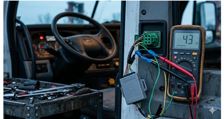
When I measured that Peterbilt 579, the bus read 43 ohms—not 60 ohms—with the key off. The install shop had added a Y-splitter with its own 120-ohm terminator right on top of the two already in the harness. Three parallel 120-ohm resistors land you uncomfortably close to 40 ohms.
J1939 is engineered around exactly two terminators, one at each physical end of the backbone. Those 120-ohm resistors deliver 60 ohms when both are in-circuit—the impedance the CAN transceivers are designed to see. Knock that number down to 40-odd ohms and the differential voltage swing collapses enough that signal edges soften and reflections pile up. At 250 kbit/s, this isn’t a hard kill. It‘s a slow corruption where the truck mostly runs and the ECM logs faults nobody can reproduce on a bay lift. I’ve pulled J1939 termination mistakes apart on more trucks than I can count, and the pattern is always identical: the physical layer gets blamed last because diagnosing it requires a multimeter, not a laptop.
Aftermarket installers routinely disconnect one terminator to insert a telematics gateway inline—and then forget to re-terminate at the device. Or the telematics hardware itself arrives with a third 120-ohm termination, dragging the parallel equivalent down to forty ohms. The bus still communicates. ECUs still acknowledge. But the signal-to-noise margin craters, and intermittent errors become the new normal. I‘ve had shops swear the bus was “working fine” while an oscilloscope showed reflections chewing up thirty percent of the bit width. The SAE J1939/11 physical layer specification defines 250 kbit/s operation over a twisted shielded pair and assumes exactly two termination resistors—no more, no less. When you lose a third of the bit sampling window to signal degradation, you’re rolling the dice on every message.
That Peterbilt ran for eleven months at 43 ohms. It also logged sporadic J1939 communication loss faults that three separate diagnostic sessions had attributed to “possible ECM internal failure.” The ECM was perfectly fine. The impedance was wrong. If you‘re not sure where to start, our J1939 backbone termination and stub length guide walks through the exact measurement sequence I use in the field. It takes under two minutes with a basic digital multimeter and tells you more than an hour of scan-tool fishing.
If your bus measures sixty ohms with power off, your terminators are intact. If it reads 120 ohms, one is missing or there’s an open circuit somewhere in the harness. If it reads forty ohms, you‘ve got an extra resistor—and a problem waiting to surface.
The Address Claim War: When Your GPS Tracker Looks Like a Brake Controller
Inside that Volvo VNL, the aftermarket GPS tracker powered up and joined the address claiming process—a J1939 routine where every ECU broadcasts its NAME (a 64-bit identifier encoding function, manufacturer, and identity) and requests a node address. The tracker’s factory-default NAME collided with one already owned by the instrument cluster. Arbitration shoved the loser off the bus. It re-claimed. Lost again. The cluster ECU, faced with an address fight it didn‘t start, interpreted the noise as a network integrity fault and dropped its display to limp mode—speed and RPM only, every other gauge dark.
That’s the address-claim war that no scan tool flags directly, because the conflict itself generates traffic, not stored DTCs. The sole external symptom was a driver who couldn‘t see fuel level or DEF gauge for eleven hundred miles. Let that sink in: a telematics device installed to enhance visibility instead created a rolling blind spot. The very thing meant to feed data to the fleet office was actively suppressing it on the dashboard.
A WABCO OnGuard maintenance manual states it plainly: if another radar or aftermarket device is connected to J1939 with the same address, the system will log a fault. The fix, per the manual, is to remove the aftermarket device. That’s not a suggestion buried in a footnote—it‘s a black-and-white directive from a component supplier who knows their radar ECU cannot share an address with a third-party logger.
Aftermarket telematics devices frequently ship with generic or default NAME configurations. When one collides with an OEM ECU’s claimed address, the result is not a hard failure. It‘s a repeating cycle of arbitration loss and re-claim attempts that generates continuous bus traffic and can shove other ECUs into fault states or fallback modes. I’ve watched a single address conflict pump bus load by over twenty percent—all from two modules fighting over who gets to be Address 0x17. That twenty percent is stolen from the bandwidth budget reserved for transmission shift messages and engine torque commands.
The technical fix is straightforward but rarely put into practice: configure every telematics gateway with a unique NAME that does not conflict with any OEM address range. Better yet, if the device only needs to read data, set it to listen-only mode—no address claiming, no acknowledgment bits, no participation beyond monitoring. A true listen-only node is invisible to the network, and that‘s exactly what you want. No address, no arbitration, no footprint. The CAN controller sits on the bus like a wiretap, reading but never writing.
Stubs, Splices, and the Slow Death of Signal Integrity
J1939 enforces stub length limits for a reason. A stub is a branch connection off the main backbone. When installers tap into the bus mid-harness using Scotch-Lok connectors or untwisted wire segments—and I have seen both, more times than I care to count—they create impedance discontinuities. At 250 kbit/s, these reflections may not kill the bus immediately. But they erode the noise margin, and after six months of vibration, temperature cycling, and corrosion, the bus starts piling up error frames faster than the CAN controllers can manage. I’ve pulled apart splice joints that looked like they‘d been soaked in saltwater because the weather seal failed—and that intermittent high-resistance connection was generating bus errors every time the truck hit a pothole. A J1939 termination stub length phantom fault is one of the most common and most expensive misdiagnoses I see in fleet shops. It mimics an ECU failure so convincingly that perfectly good modules get replaced.
Some devices make this worse by transmitting during startup even when configured for passive monitoring. Certain CAN controllers suppress data frames in listen-only mode but still allow error frames or acknowledgment bits onto the bus. From the network’s perspective, that is still active participation—and on a sensitive J1939 implementation, it is enough to raise faults. Always verify with a CAN bus analyzer that your telematics device generates zero dominant bits in every operating mode, including startup and shutdown. A J1939 transceiver can appear to still communicate while generating enough bus noise to confuse every other module on the network. Don‘t trust the device data sheet. Trust the scope trace.
The Numbers Behind the Noise
A truck out of service costs between four hundred forty-eight and seven hundred sixty dollars per day in lost revenue. If a network-level J1939 fault triggers an intermittent derate event that takes three diagnostic sessions to locate—each involving a technician, a bay, and possibly an unnecessary ECM replacement at roughly two to four grand a unit—the total cost of that single integration error can easily blow past fifteen thousand dollars before anyone identifies the aftermarket device as the root cause. That’s not a worst-case scenario; I‘ve documented exactly this chain of events on more than one fleet account. I’ve written about how a single J1939 network termination and stub length issue can generate fifteen thousand dollars in maintenance cost before anyone thinks to check the physical layer. The parts invoices stack up while the real problem is a ten-dollar resistor.
Now multiply that across a fleet of fifty, a hundred, or five hundred trucks where the same installation process was repeated. Across a hundred-truck fleet with the same installation pattern, the exposure crosses one million dollars before anyone opens a wiring diagram. And because these bus faults are intermittent by nature, they tend to be dismissed as “gremlins” until the pattern becomes undeniable. A J1939 ground offset across a fleet can pile up six-figure diagnostic waste before a single multimeter measurement identifies it. The math is brutal: five hundred trucks multiplied by a single extra day of diagnostic labor per unit, and you‘re staring at real money spent chasing a ghost.
A standard J1939 data frame consumes roughly 108 bits including inter-frame spacing. At 250 kbit/s, that’s about 0.43 milliseconds per frame. When a telematics device transmits address claims, request PGNs, or heartbeat messages—especially during bus-off recovery attempts—it injects bus load that competes directly with the engine and transmission messages that keep the truck operational. A bus load of sixty to seventy percent is already considered high without proper network management. Throw in an uncalibrated third-party device, and you are operating dangerously close to a margin that was never designed for aftermarket expansion. I‘ve measured bus loads spiking above ninety percent on trucks equipped with multiple unmanaged telematics boxes—at that level, even a single error frame can trigger a cascade of message timeouts. The J1939 backbone design expects 60 ohms for a reason; deviate from it and the derate becomes a question of when, not if. The impedance target isn’t a suggestion. It‘s the value the entire CAN network was simulated against before the first harness drawing was released.
The Integration Problem Nobody Talks About: Warranty Liability
There is a legal dimension here that most fleet procurement processes completely overlook. OEM warranty terms increasingly stipulate that proven CAN bus corruption caused by third-party telematics equipment makes the installer liable for consequential damage. This is not hypothetical. I’ve watched a fleet operator eat a six-figure repair bill because an aftermarket gateway‘s intermittent transmission pattern was captured in the ECM freeze-frame data as the trigger for a transmission control module failure. The OEM denied the claim. The telematics vendor pointed at the installer. The installer had zero engineering documentation proving the device was configured for passive-only operation.
When integration goes wrong, the liability chain crumbles fast. The fleet operator—who bought the telematics solution to save money—ends up holding the bag. If you’re deploying fleet telematics, make certain your installation records include a bus resistance measurement, a screenshot of the device configuration, and a CAN trace proving zero transmission. Without that paper trail, you‘re banking on the OEM being generous. I’ve yet to see generosity win against a documented bus fault signature in an ECM data freeze. The data tells a story that no amount of goodwill can rewrite.
What a Proper Integration Actually Looks Like
After diagnosing hundreds of these failures across multiple OEM platforms, I‘ve put together a checklist that separates reliable integrations from the ones that will haunt a fleet six months later. This isn’t academic theory. These steps come from crawling under trucks and staring at oscilloscope traces until the problem reveals itself. The tools are simple; the discipline is what makes the difference. A J1939 physical layer ROI analysis with basic tools shows how a sub-one-thousand-dollar toolkit can slash fleet downtime by seventy percent. That‘s not a projection. It’s what happens when you stop guessing and start measuring.
Before Installation
- Identify the OEM-recommended connection point. On Volvo, this is the DL1 J1939 data link connector or the RP1226 aftermarket interface. Do not splice into the backbone mid-harness unless the OEM explicitly permits it. I can‘t count how many times I’ve seen a perfectly good telematics gateway installed on the wrong connector, triggering ghost faults that took weeks to trace. The connector pinout exists for a reason; the OEM placed the right signals on the right pins for a specific integration path.
- Read the bus resistance and write it down. Measure CAN-H to CAN-L with power off. I‘ve had fleets skip this, then burn days chasing a fault that a simple before-and-after resistance comparison would have flagged in two minutes. If you see 60 ohms, you’re starting from a healthy backbone. Anything else—43 ohms, 120 ohms, 72 ohms—stop and identify why before you add a device. Document the baseline. That single number is your get-out-of-jail card when the next intermittent fault surfaces. I cover the exact J1939 physical layer troubleshooting sequence with 60-ohm and waveform checks for anyone who wants the step-by-step. Write the number on the work order and snap a photo. Six months later, when the truck acts up, you‘ll want that reference.
- Verify the bit rate. While 250 kbit/s is most common, some platforms use 500 kbit/s, particularly on newer chassis with higher data throughput needs. A bit rate mismatch won’t just cause errors; it can make the bus completely deaf to your device. I check this with a bus monitor before I even open the parts box.
During Installation
- If the connection method involves removing a terminator, ensure the device or its harness re-terminates the bus at exactly 120 ohms. Never leave the bus unterminated, not even for a short test. An unterminated backbone will generate reflections that can corrupt messages from the moment the network powers up.
- Configure the device for listen-only operation if no transmission is required. Verify with a CAN bus analyzer that the device generates zero dominant bits during startup, normal operation, and shutdown. I check for any stray acknowledgment bits during the first 30 seconds after power-up—that‘s when most CAN controllers misbehave. A single ACK bit is enough to announce a new node’s presence to the network.
- Assign a unique, non-conflicting NAME if the device must participate in address claiming. Do not use the factory default. Check the OEM address range documentation to pick a safe node address. Never assume the default is safe. Defaults are set by firmware engineers who have no idea what vehicle the device will land in.
- Maintain stub lengths under the specified maximum—typically one meter at 250 kbit/s per SAE J1939-15 guidance. Shorter is always better. If you must run a longer stub, use a repeater or isolate the branch properly. The J1939 termination and stub length phantom fault cost article breaks down exactly why exceeding stub length limits generates reflections that no scan tool can see. Every extra inch of stub adds capacitive load and eats into the timing margin.
- Use twisted-pair wiring for any extension. Keep the twist rate consistent. Untwisting even a few inches of CAN bus wire can create an impedance bump that generates reflections. The twist is what rejects common-mode noise. Flatten it, and you’ve turned a differential bus into an antenna.
After Installation
- Measure bus resistance again with power off. If it has changed, find out why before starting the engine. A shift from 60 ohms to something else means you‘ve introduced a termination fault that will degrade signal quality under load. If the number moved, something you did altered the network topology. Don’t start the truck until you understand what.
- Start the engine and monitor the bus with a scope or J1939 analyzer for at least fifteen minutes. Look for error frames, unexpected message bursts, or bus-off events. Pay close attention during the ECU initialization window—some aftermarket devices transmit a burst of address claims the moment they see ignition voltage. A J1939 waveform analysis with a 200-dollar USB scope can reveal edge-rate problems and ringing that a scan tool will never report. A clean differential waveform with sharp edges and minimal overshoot is your confirmation that the physical layer is healthy.
- Verify that all existing ECUs are present and communicating normally. Check for any newly stored fault codes related to J1939 communication loss or abnormal update rates. If a code appears after your installation that wasn‘t there before, don’t clear it and walk away—trace it. Learn to diagnose a J1939 data link error in 20 minutes before the truck leaves the bay. The code is the first clue. The multimeter and the scope will tell you the rest.
The tool set required is modest. A multimeter for resistance checks. A two-channel USB oscilloscope for waveform analysis. A J1939 monitor that can decode PGNs, display bus load, and flag error frames. Combined cost is well under a thousand dollars—roughly one-third the cost of a single unnecessary ECM replacement. I keep all three in a single Pelican case. That case has paid for itself more times than I can count. A CAN bus physical layer test saves eight hundred dollars in diagnostic fees on the very first use. After the first successful diagnosis, you‘ll wonder how you ever worked without them.
Common Mistakes I See Repeatedly
Through twenty-plus years of factory experience manufacturing J1939 cabling and troubleshooting field installations, certain patterns resurface again and again. These aren’t edge cases—they‘re the bread and butter of my field diagnostics calls. I see them repeated across fleets, geographies, and OEM platforms because the root cause is never the hardware. It’s the process.
The “It Worked on the Bench” Assumption. A device tested on a simulator with one ECU behaves completely differently when plugged into a live network with gateway modules, power transients, and real message traffic. Bench validation is necessary. It is not sufficient. I‘ve seen devices that ran flawlessly on a CAN simulator fail within ten minutes on a real truck because the vehicle’s alternator noise shoved the common-mode voltage just far enough to trigger bit errors. A bench power supply doesn‘t ripple like a charging system under load.
The Swapped CAN-H/CAN-L Connection. Green to yellow, yellow to green. It happens. The bus may still communicate partially if one device corrects, but error frames accumulate and intermittent faults become impossible to isolate. A wiring mistake like this won’t always kill the bus outright—it‘ll degrade it just enough to gaslight your entire diagnostic process. The differential signal still toggles, but the polarity is inverted, and every recessive bit turns into a timing challenge for the receivers.
The Unfused Power Tap. Tapping accessory power without an inline fuse is not merely a fire hazard. Power supply noise couples into the CAN transceiver through the ground reference, producing common-mode voltage shifts that look exactly like bus faults to the receiving ECUs. Always fuse your telematics device on its own circuit, and keep the ground wire as short and direct as possible. A noisy power supply is a noise source injected straight into the most sensitive part of the CAN physical layer.
The Firmware Update That Re-Enables Transmission. I’ve debugged a fleet where every device was set up for passive monitoring during installation. A subsequent firmware update reset the configuration to default—which included periodic heartbeat transmission. The fault returned across the entire fleet within two weeks, and no one correlated it with the update until the third truck rolled in with identical symptoms. Not a single technician had asked, “Did anything change recently?” because the answer was always “just a routine update.” A routine update that silently flips a configuration bit can undo months of careful integration work in a single flash cycle.
The Missing Ground Reference. J1939 transceivers need a common ground. If the telematics device grounds through a different path than the vehicle ECUs, the common-mode voltage can drift outside the transceiver‘s operating range, producing intermittent communication failures that meter tests will never catch. I’ve seen devices grounded to the cab frame while the J1939 backbone referenced engine block ground—a classic recipe for ground loop noise that corrupted every third data frame. This is exactly the scenario I detailed in the J1939 ground offset fleet cost article; one bad ground reference cost that fleet over eighty thousand dollars in misdiagnosis before anyone checked the ground path. The voltage difference between two ground points under load can exceed the common-mode range of a CAN transceiver, and at that point the bus goes deaf intermittently.
The Factory Perspective: Why Physical Layer Quality Matters
In two decades of manufacturing J1939 cables, connectors, and harnesses, I‘ve learned that the physical layer is where most network problems live—and where most diagnostic effort gets wasted looking anywhere else. A scope trace showing rounded edges, excessive ringing, or inconsistent differential voltage tells you more about network health than any scan tool. You can’t fix a physical-layer fault by reflashing an ECU, but I‘ve watched shops try. The J1939 scope bench analysis of edge rates, ringing, and differential voltage is the first thing I run when a truck rolls in with an unexplained bus fault. Before I connect any diagnostic kit, I look at the waveform. It answers the question the scan tool can’t: is the signal even arriving cleanly?
Our factory operates under ISO 9001, IATF 16949, and ISO 14001 certifications. Every cable assembly goes through a four-step quality inspection: continuity, pinout verification, hipot testing, and visual inspection under magnification. We maintain climate-controlled warehousing under 5S management protocols because humidity and temperature cycling are not abstract concerns—they directly affect connector contact resistance and long-term reliability. A connector that tests fine in a 22°C humidity-controlled lab can develop intermittent opens after a winter of road salt and thermal shock. We test with that reality in mind. Our ISO 14001 certification reflects the environmental management discipline that keeps our production floor consistent enough to guarantee those test results batch after batch. Consistency on the floor means consistency in the field.
The J1939 9-pin Deutsch connectors we ship are RoHS-compliant, UL-listed, and REACH-documented. That is not marketing fluff. It is the baseline for guaranteeing that the connector you install today does not become the intermittent fault you chase three years down the road. I‘ve spent hours under dashes with a flashlight, tracing a CAN bus fault back to a connector that looked pristine on the outside but had corroded terminals just deep enough to create a high-resistance path at the exact moment the engine reached operating temperature. That’s why we inspect every contact surface under magnification before it leaves the floor. Our IATF 16949 certification isn‘t a wall decoration—it’s the quality system that catches that corrosion risk before the connector ships. For additional compliance documentation, our certification portfolio covers the full regulatory landscape that fleet procurement teams require. Having the paperwork in order before the audit is how you pass without scrambling.
For telematics integrators and device manufacturers, we deliver complete OEM customization: logos, branding, cable lengths, color coding, and wire gauge specifications matched to the application. If your device demands a custom pinout or a specific connector orientation—right-angle, low-profile, Y-splitter—we build to your engineering specifications, not a catalog number. Every assembly is tested for continuity, pinout, hipot, and visual under magnification before it leaves the floor. When a fleet orders five hundred custom J1939 harnesses, they get five hundred individually tested assemblies, not a batch-tested sample. If you‘re unsure which connector series fits your operating environment, our Deutsch connector series selection guide walks through the environmental and budget trade-offs. Choosing the right connector body material and seal compound upfront prevents a corrosion failure five years down the road.
When you are trying to keep a fleet of trucks on the road, the difference between a cable that was tested once per batch and a cable that was tested individually is the difference between confident diagnosis and phantom electrical faults that eat technician hours and fleet uptime. I’ve seen a single bad J1939 cable generate more diagnostic labor hours than the cable cost by a factor of a hundred. The J1939 Deutsch DT and HD connector guide explains why connector selection at the specification stage determines whether you get a five-year harness or a six-month headache. A DT connector in a high-vibration, high-pressure-wash environment will fail far sooner than an HD-series part designed for that exposure.
FAQ: Practical Answers for Engineers and Fleet Managers
1. Why does my truck run fine for weeks after telematics installation, then start throwing J1939 faults?
Thermal cycling, vibration, and moisture ingress at the splice points degrade signal integrity gradually. What passes at installation in a climate-controlled bay may fail six months later after a winter of salt spray and temperature swings. The device didn‘t break. The installation did. I’ve traced failures back to wire splices that looked perfectly solid on day one but turned into high resistance after the first freeze-thaw cycle. A wiggle test protocol for J1939 harness opens is the fastest way I know to find these before they strand a driver. When the fault only appears on rough roads or after an overnight cold soak, you‘re chasing a mechanical opening, not an electronic one.
2. Can I just plug a telematics gateway into the 9-pin diagnostic connector and call it done?
Sometimes. But many OEMs route the diagnostic connector through a gateway or isolate it from the backbone with a different termination scheme. Volvo explicitly recommends the DL1 or RP1226 connector over the diagnostic port for permanent telematics installations. Check the vehicle-specific documentation before assuming the diagnostic connector is your safest entry point. Plugging into the diagnostic port can work for temporary data logging, but for permanent fleet telematics, it’s often the first thing I unplug when diagnosing an unexplained CAN bus issue. Knowing which J1939 Type 1 to Type 2 adapter fits your vehicle can save you from the wrong connection point entirely. The adapter you choose determines whether your device sits on the backbone or behind a gateway.
3. How do I know if my device is transmitting when it should be listening?
Connect a J1939 bus monitor before and after installation. A properly configured listen-only device generates zero bus traffic. If you see address claims, request PGNs, or any frames originating from the device‘s address, the configuration is wrong. I run this check for at least ten minutes after ECU initialization is complete, and again after a key cycle—some devices only transmit a heartbeat on the second power-up. One missed heartbeat during bench testing becomes a network-wide disruption on the vehicle.
4. What is the correct resistance reading across CAN-H and CAN-L with everything powered off?
Between CAN-H and CAN-L, with the ignition off and any aftermarket modules disconnected, you’re looking for roughly 60 ohms. That tells you both 120-ohm terminators are in-circuit and parallel. If you see 120 ohms, you‘re reading through a single terminator—either one is open, or you’re measuring across a stub instead of the backbone. If you see around 40 ohms, you‘ve almost certainly got a third 120-ohm resistor somewhere—likely inside a Y-harness that quietly re-terminates a branch. I’ve also caught 72 to 74 ohms when a battery lead wasn‘t fully disconnected and was feeding a weak path through an ECU’s internal protection diodes. Always isolate the bus completely before trusting the meter. If you need the exact J1939 CAN-H and CAN-L voltage ranges for a healthy bus, I keep a reference chart in my tool kit. Recessive should sit around 2.5V. Dominant should pull apart cleanly. Anything else points to a physical-layer fault.
5. Can an aftermarket telematics device void my vehicle warranty?
The device itself does not void the warranty. But if the OEM can demonstrate that the device caused or contributed to a failure—and freeze-frame data from the ECM can make that case—the repair may not be covered, and liability can extend to consequential damage on adjacent systems. I‘ve seen OEM field service engineers pull ECM freeze-frame records that showed the exact microsecond an aftermarket gateway began flooding the bus with arbitration-loss messages right before a TECU failure. That’s when the warranty discussion ends and the liability discussion begins. A J1939 bit sampling error can produce a phantom fault that the ECM freeze-frame captures perfectly—and the OEM will use it. The freeze-frame is a timestamped record. If it shows your device‘s address claiming in the milliseconds before the fault, you have no argument.
6. Why does my telematics gateway work perfectly on a bench test but cause faults in the vehicle?
Bench setups lack the electrical noise, voltage transients, concurrent bus traffic, and gateway ECU interactions present in a real vehicle. ECUs enter diagnostic modes on the bench that they never use in operation. Validation must happen on a representative vehicle, not just a simulator. I’ve run devices on a bench CAN network for forty-eight hours without a single error frame, only to see them fail within five miles of road testing because the alternator ripple pushed the signal-to-noise ratio past its threshold. A J1939 bit sampling error and reflection causing bus-off is the kind of problem that never shows up on a simulator but appears within the first hour on pavement. The alternator, the injector solenoids, and the ABS pump are all noise sources that don‘t exist on your bench.
7. Do I need shielded or unshielded twisted pair for my telematics extension harness?
J1939-15 specifies unshielded twisted pair for 250 kbit/s operation. In environments with high EMI—near inverters, electric motors, or high-current switching—shielded cable may be warranted. But improper shield termination (grounding at both ends, creating a ground loop) can introduce more problems than it solves. Follow the device manufacturer’s guidance. When in doubt, I test with unshielded first in the installed environment and monitor the error frame rate before committing to a shield design. A shield grounded at both ends is a ground loop waiting to couple noise directly into your signal reference.
8. What tools do I need to diagnose a J1939 telematics integration issue?
At minimum: a quality digital multimeter for resistance and voltage checks, a two-channel oscilloscope capable of at least 50 MHz bandwidth for waveform analysis, and a J1939 bus monitor that reports bus load, error frames, and message-by-message traffic. A scope lets you see things a scan tool cannot—reflections, noise coupling, collapsing differential voltage. I keep a PC-based J1939 analyzer running on every integration job so I can capture the entire power-up sequence and review it if something looks off later. For anyone who needs the wiring reference on hand, the J1939 wiring diagram for CAN-H and CAN-L is the sheet I keep laminated in my toolbox. Know the pinout cold. A swapped pair wastes hours.
9. How often should I re-check a telematics integration after initial installation?
At the first scheduled preventive maintenance interval following installation. Re-measure bus resistance. Re-verify that the device is not transmitting unexpectedly. Check for any J1939-related fault codes that have accumulated since installation. If you changed firmware on the device, treat it as a new installation and re-verify everything. I recommend fleets add a bus health check to their standard PM checklist—it takes less than two minutes with a multimeter and a J1939 monitor, and it catches problems before they strand a driver. A J1939 voltage drop field test fits into a PM inspection without adding labor and catches ground reference drift before it becomes a road call. Two minutes every PM beats a five-hour roadside diagnostic.
10. Can I run multiple aftermarket devices on the same J1939 bus?
Technically possible. Practically dangerous without careful planning. Each additional device adds bus load, increases stub complexity, and introduces another potential source of address conflicts, terminator errors, and noise coupling. Test the complete configuration on one vehicle for at least a thousand miles before fleet-wide deployment. I‘ve seen multi-device setups work perfectly on paper but generate intermittent bus-off events in the real world because the combined capacitive load of the extra stub connections shifted the signal rise time just enough to violate the bit timing specification. If you’re mixing connector types across devices, a J1939 Type 1 and Type 2 adapter buyers guide helps avoid the physical-layer mismatch that can masquerade as a software problem. Run a thousand miles, log every bus statistic, and review before you roll it out to the rest of the fleet.
The Bottom Line
Aftermarket telematics should make a fleet smarter, not quieter. But the J1939 network treats every new device as an unknown—and unknowns, in a real-time control system, get expensive fast.
You don‘t have to pull the telematics device. You have to integrate it so the network never knows it’s there: with respect for the physical layer, with passive monitoring as the default, with unique addressing, and with verification at every step from installation through the life of the vehicle. That‘s not a marketing promise. It’s an engineering discipline, and it‘s the only approach I’ve found that keeps fleet J1939 networks reliable after the aftermarket integration is complete. Mastering J1939 physical layer troubleshooting is the skill that separates a five-minute bus check from a five-day diagnostic goose chase. The multimeter and the scope answer questions the scan tool can‘t even ask.
If your fleet runs J1939, and you are deploying aftermarket gateways, trackers, or data loggers, the difference between an asset and a liability comes down to the details of the connection. We have spent twenty years engineering those details into every cable assembly we manufacture—not because the marketing department thought it would sound good, but because we have seen up close what happens when someone gets it wrong. And what happens is a truck sitting dead on the shoulder with a CAN bus fault that nobody can locate until they unplug the one thing everyone assumed was innocent. Intermittent J1939 faults found with a wiggle test is the story I tell fleets when they ask me why a ten-cent splice is worth ten minutes of verification. The cost of verification is orders of magnitude smaller than the cost of the breakdown it prevents.
Need a custom J1939 cabling solution engineered for your telematics hardware? We provide OEM-customized J1939 cable assemblies—your branding, your pinout, your specifications—with full engineering support from concept to production. ISO 9001, IATF 16949, ISO 14001 certified manufacturing. Every assembly tested for continuity, pinout, hipot, and visual under magnification. When your fleet uptime depends on a connector that won’t fail on a freezing January morning in Winnipeg, the difference between batch-tested and individually-inspected is the difference between a schedule and a roadside tow bill.
📩 Contact our engineering team: https://obd-cable.com/contact/
📲 WhatsApp direct line for technical inquiries: Chat with Linda on WhatsApp
