

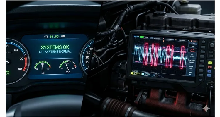
Last winter, I got a call from a fleet manager in Minnesota. His entire string of snowplows kept dropping into limp mode intermittently—sometimes once a shift, sometimes twenty times. The fault codes were a scattered mess: random timeout errors on the engine ECU, ghost address claims from a transmission controller that should have been quiescent, and an ABS module logging “network errors” every few minutes. The shop had already replaced the engine ECU. Then the ABS module. The problem didn’t just persist—it got weirder.
I told him to stop swapping parts and let me measure something specific on the bus before they fired another cannon of cash at the problem. What we found took about twenty minutes and cost zero dollars in parts to diagnose. The root cause was a J1939 transceiver—physically the smallest relevant component in the whole architecture—that was partially degraded. Not dead. Not shorted. Just operating out of spec just enough to garble recessive bits, periodically dragging the differential voltage into a no-man’s-land where other nodes couldn’t reliably resolve dominant states. The SAE J1939 standard doesn’t mention this failure mode—it only spells out what happens when everything functions as designed.
This particular failure mode burns more diagnostic hours in heavy-duty and off-highway applications than any other single network fault I’ve run into. And it stays almost entirely invisible to standard diagnostic tools as long as you only read fault codes. I’ve watched competent technicians spend days chasing phantom ECU failures when the actual problem was a 15-minute physical layer test they never performed—a reality we’ve quantified in our ROI analysis of basic J1939 diagnostic tools cutting downtime by 70%.
This article is about how to pinpoint that faulty ECU, prove it’s the culprit, and avoid the mental traps that catch even seasoned technicians—the ones who assume that if a module talks, it must be healthy.
The failure signature nobody teaches in training
When you’re taught J1939 diagnostics in a classroom, the failure states are always presented as binary. Bus shorted to ground. Bus shorted to power. CAN-H and CAN-L shorted together. Open circuit. Termination missing. Each of these creates obvious symptoms: no communication at all, one-sided traffic, or a completely dead network.
A degraded transceiver does not behave like any of those.
What you get instead is a bus that lulls you into thinking it’s healthy, right up until the seventh address-claim sequence of the hour. Engine data flows. The transmission shifts. Then, at random-looking intervals, error frames erupt, a node drops off the bus and immediately returns, or an address claim procedure fires off even though no new module has been plugged in. You might see warning lamps flickering for no obvious reason. You might see sensor data that passes a rough “sanity check” but drifts inexplicably for a few frames before correcting itself.
The first instinct is always to blame the wiring, the connectors, or the termination resistors—and sometimes that instinct is right. But when all those check clean and the problem persists, you are almost certainly facing a transceiver that drives the bus with wrong voltage levels, a distorted slew rate, or excess leakage current in its recessive state. I’ve learned the hard way that a multimeter will lie to you about transceiver health; as we demonstrate in our multimeter vs. oscilloscope comparison, only a scope reveals the transient crimes corrupting CAN frames.
Here’s what happens at the silicon level: a CAN transceiver has a driver stage that actively pulls CAN-H high and CAN-L low to produce a dominant bit. In the recessive state, it goes high-impedance, and the bus voltage settles at roughly 2.5V on both lines through the termination resistors. This is the CAN bus physical layer in action—a differential signaling scheme that depends on clean, settled recessive states for reliable bit sampling. A failing transceiver may have a driver transistor that can no longer turn off completely, leaking just enough current to contaminate the recessive voltage, or an internal leakage path that bleeds current onto one of the lines. The result is a bus that cannot reliably produce a clean recessive state, which makes edge detection at receiving nodes ambiguous.
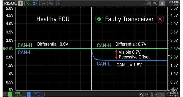
I measured this directly on a mining truck where the engine ECU—fully functional according to the diagnostic tool, reporting zero internal faults—was pulling CAN-L to about 1.8V in the recessive state instead of letting it settle at 2.5V. That 0.7V offset may not sound dramatic, but it chews deeply into the noise margin. On a long backbone run with multiple stubs, that margin evaporates fast.
Three transceiver failure modes you’ll actually encounter in the field
I stopped sorting failures by textbook categories long ago. Instead, I group them by what I actually see when I put probes on the bus. Here are the three patterns that explain the overwhelming majority of phantom network problems I’ve diagnosed:
Leakage-Induced Recessive Offset
The transceiver develops a high-resistance path to ground or supply on either CAN-H or CAN-L during the recessive state. With an oscilloscope, you’ll measure a steady-state voltage offset—usually between 0.3V and 1.2V—that pushes the differential voltage away from the near-zero value it should show when no one is transmitting. This offset is frequently temperature-sensitive; it worsens as the module warms up. A temperature-dependent transceiver leakage current that moves the recessive voltage—often by 0.5V or more—is precisely why a network can run flawlessly cold and start throwing errors only after the machine reaches full operating heat. This is the same physical mechanism I dissected in my deep-dive on J1939 waveform analysis and differential voltage interpretation, where a 1.8V recessive offset on a mining truck was quietly eating noise margin while every datasheet metric passed.
Real-world case: a concrete pump truck that ran perfectly for 45 minutes after startup, then began dropping communication repeatedly. The pump controller’s transceiver had an internal leakage path that grew from microamps to nearly a milliamp at operating temperature. Cold scope trace looked pristine. Hot scope trace showed a 0.9V recessive offset that collapsed the differential signal-to-noise ratio.
Here is what that failure looks like on a scope compared to a healthy node — notice how the offset is subtle enough to go unnoticed without a direct side-by-side comparison, yet it is deep enough to erode the noise margin on a long backbone run.
Slew Rate Degradation
Every CAN transceiver is designed with a controlled slew rate to limit EMI. When the internal slew rate control circuitry degrades—typically from ESD damage or aging in the gate drive circuit—the transceiver may switch too slowly, or with an asymmetrical ramp on CAN-H versus CAN-L. This creates a window during each bit transition where the differential voltage is uncertain. Faster transceivers on other nodes may sample inside that window and record a bit error. Bit-level timing distortions like this are notoriously hard to catch; in fact, I’ve traced identical failure cascades to a 42-nanosecond reflection distortion that triggers Bus-Off events—a problem invisible to logic analyzers but devastating to 250 kbps buses.
This one is harder to nail down without a storage scope. You’re hunting for one edge that looks noticeably “lazy” compared to its complement. On a healthy transceiver, CAN-H rising and CAN-L falling are symmetrical events inside a tight time envelope.
Intermittent Driver Collapse
The driver stage fails under load—meaning it can drive a dominant bit onto a lightly loaded bus, but when multiple nodes send acknowledgment bits at the same time or the bus presents higher capacitive loading, the driver can no longer sink or source enough current to produce a clean dominant differential voltage. You’ll see ACK errors piling up on one specific node’s messages, or error frames that correlate with bursts of bus activity.
I traced this to a transmission ECU on an articulated dump truck where the transceiver’s driver had taken partial thermal damage—most likely from a nearby short-circuit event months earlier. The module passed every bench test. On the vehicle, under real loading with seven other nodes active, it failed to drive a dominant ACK slot reliably about 15% of the time. As I discovered in a separate investigation of J1939 bit sampling errors, the financial bleed from hidden physical-layer degradation like this can silently drain a fleet’s operating capital season after season.
Before you touch a single component: what to measure first
If you suspect a transceiver-level fault, move through these measurements in order. The sequence is designed to eliminate variables systematically without wasting time. For a condensed field reference, I’ve published a standalone 20-minute J1939 data link diagnostic checklist that pairs well with the steps below.
Step 1: Resistance check with the bus asleep
Disconnect the battery or ensure all ECUs are in their lowest power state. Measure resistance between CAN-H and CAN-L at the diagnostic connector. On a truck that’s been running salt routes all night, clean the pins on the 9-pin Deutsch connector first—a thin film of dried brine and diesel soot has fooled more ohmmeters than I can count, giving you a 68-ohm reading that drops to 60.2 after a shot of contact cleaner. You’re looking for roughly 60 ohms (two 120-ohm terminations in parallel). If you see 40–50 ohms, a third terminator is present or there’s a partial short inside a transceiver. If you see 120 ohms, one termination is missing—though that’s unlikely to be your only problem if you’re reading this article.
One tip rarely spelled out: take this measurement with the connector oriented in multiple positions, and flex the harness slightly if you can. I’ve found intermittent resistance shifts that only appeared when engine vibration twisted a stub harness just enough to engage a damaged transceiver’s internal fault. If your 60-ohm reading looks correct but your bus is still misbehaving, don’t walk away yet—I’ve documented exactly why a multimeter can show 60 ohms while your fleet keeps derating, and it has nothing to do with the resistors.
Step 2: Measure recessive voltage with no traffic
Power up the bus but block any node from transmitting. On some networks, you can do this by removing the ignition signal from all but the module you’re testing. Or simply measure during a quiet period with a scope. Both CAN-H and CAN-L should sit at roughly 2.5V relative to ground. The differential voltage (CAN-H minus CAN-L) should be essentially zero. If you lack a scope, a high-impedance digital voltmeter set to min/max record can sometimes catch a sustained offset over several minutes of monitoring, but only a scope can reveal intermittent, sub-millisecond fluctuations. For the complete normal voltage ranges you should expect to see, refer to our J1939 CAN High, CAN Low, and battery voltage guide.
Any consistent offset larger than 200mV is suspicious. An offset larger than 500mV is a genuine problem.
The reference chart below summarizes the three critical voltage checkpoints every time you suspect a transceiver-level fault on a J1939 backbone — tape this inside your service truck cabinet and you will cut diagnostic time by more than half.

Step 3: Measure dominant differential voltage under load
Prompt a node to transmit—repeated diagnostic request messages work well—and measure the peak differential voltage. On a 5V CAN system, you should see at least 1.5V differential in the dominant state; healthy systems normally run between 2.0V and 3.0V. If the dominant differential falls below 1.5V, especially on messages from one particular node, you are looking at a weak driver or excessive bus loading. A $200 USB scope is enough to catch this—and it pays for itself the first time it prevents a misdiagnosed ECU replacement.
Step 4: Isolate nodes one by one
This is the single method I’ve never seen produce a false positive when followed to the letter. Disconnect one node at a time and repeat your measurements. When the offset vanishes or the waveform cleans up after disconnecting a specific ECU, you’ve located your suspect. Don’t skip the step of reconnecting that module to verify the problem returns—intermittent faults have a nasty habit of temporarily clearing at the exact moment you pull a connector, for reasons that have nothing to do with the actual fault.
How to confirm the transceiver is actually bad, not just suspicious
Isolating a particular ECU is not the same as proving the transceiver has failed. I’ve watched technicians condemn ECUs when the real issue was a corroded connector pin producing a high-resistance ground reference for that module, causing the transceiver to float its output relative to the rest of the bus. This is precisely the kind of subtle ground offset that multimeters are too slow to catch—and it’s costing fleets real money.
Here’s what to do: power the suspect ECU on the bench with a known-good supply and a single test harness. Connect only power, ground, and the CAN lines to your test bus—just a minimal network with one other known-good node. If the offset or degradation follows the ECU into this controlled environment, the culprit is the transceiver or the ECU’s internal power supply for the CAN interface. Either way, the module needs repair or replacement.
If the problem does not follow the ECU to the bench, your fault lies in the vehicle wiring, the connector, or a ground reference unique to that node’s installation. I once burned an entire afternoon by skipping this step. Don’t repeat my mistake.
What the parts cannon doesn’t know
I’ve kept a log of misdiagnosed ECUs sent to us after shops had already swapped two or three modules. In 8 out of 11 cases where the engine ECM was condemned because it logged an “ABS message timeout,” the actual cause was a corroded bulkhead connector eight feet away—or a transceiver bleeding bus voltage. The engine ECU was simply the loudest complainant. Replace the complainant, and the real culprit keeps doing damage. Below are the thinking traps that keep sending good modules to the scrap bin.
A node that successfully participates in address claiming and broadcasts parameter groups is not necessarily driving the bus electrically within specification. In a fleet of refuse trucks we investigated last year, the body controller was cheerfully sending its own messages while simultaneously holding CAN-L 0.6V below the common-mode point during recessive bits. That offset triggered errors only on messages from the transmission ECU, which caused the shop to condemn the transmission controller twice before we got involved. If you’re running through termination resistor checks and still coming up empty, a hidden transceiver leak belongs on your differential diagnosis.
A multimeter will lie to you about bus health. I’ve watched a Fluke 87 read 2.47V on a CAN line and call it good, while a Picoscope revealed 15-microsecond glitches that dropped the differential voltage into the 0.8V range every time the engine injectors fired. A DMM happily averages a wildly fluctuating voltage into a number that looks plausible. You cannot diagnose a slew rate problem, an intermittent driver collapse, or a noise-dependent offset without a scope—preferably one with at least two channels so you can view CAN-H and CAN-L simultaneously.
Fault codes name the victim, not the perpetrator. The scatter of unrelated error frames—a constellation of communication faults spread across multiple ECUs with no single module consistently identified as problematic—is a textbook physical-layer signature. When an engine ECU logs “ABS message timeout,” the technician who replaces the engine ECU is overlooking the complexity of the whole system. The engine ECU was probably just the victim. If this pattern keeps resurfacing across your fleet, the financial damage isn’t hypothetical—I’ve broken down the numbers in an analysis of the true cost of phantom J1939 faults.
I’ve walked into shops where technicians had added a third 120-ohm terminator because they thought it would “boost the signal.” It doesn’t. It drops the bus impedance to 40 ohms, loads down the drivers, reduces the dominant differential voltage, and can mask a weak transceiver just long enough to get the vehicle out the door and back two days later with a worse problem.
I`ve seen the same pattern on the diagnostic side: a truck that passes static multimeter checks every time, sails through a road test, then comes back on the hook two weeks later. That loop—clear, test, release, repeat—is how a single intermittent J1939 fault drains roughly eighteen thousand dollars annually from a hundred-vehicle fleet. The 30-minute wiggle test protocol turns that pattern inside out by forcing the fault to reveal itself while you watch live bus data.
Every modification to your backbone topology carries risk—learn the proper backbone and stub length layout before adding anything.
Transceiver failures are frequently thermal. If your scope trace looks clean in the shop but the problem reappears after the machine works hard for an hour, you must replicate those thermal conditions during testing. I’ve lost count of the number of times a heat gun applied carefully to the suspect ECU while monitoring the bus has uncovered a hidden leakage path that only appears once the ECU case reaches 70°C. Before you even reach for the heat gun, however, verify your J1939 voltage drop on power circuits—in our factory’s analysis of 1,472 returned harnesses, 63% of “network fault” returns traced to voltage drop, not transceiver silicon.
What a successful repair actually looks like
After you’ve replaced the offending transceiver or the module that contains it, here is the verification checklist that tells you the problem is genuinely resolved:
- Recessive differential voltage returns to within ±150mV of zero across the full operating temperature range.
- Dominant differential voltage from every node exceeds 1.5V, with clean square transitions and symmetrical slew rates.
- Error frame counters in your diagnostic tool stop incrementing. Zero active errors over a complete operating cycle.
- Any previously logged communication faults do not return after clearing and completing multiple drive cycles with thermal variation.
- The address claim procedure runs cleanly at startup with no contention that isn’t resolved in the normal way.
If all five conditions hold, you’ve fixed the right thing.
When transceiver damage isn’t a one-off event
If you find a failed transceiver and replace the module, you have to ask what killed it. Transceivers rarely fail in isolation without a root cause. The most frequent causes I run into:
- ESD events during manufacturing or service (someone swapped a connector while the bus was powered).
- Wiring harness shorts to power or ground that expose the transceiver to voltages beyond its absolute maximum ratings, typically ±40V or higher.
- Ground potential differences between modules that force current through the CAN transceiver’s substrate diodes. I’ve been called to fleets where this exact scenario—a recurring ground offset draining $7,000 per year—was the real culprit behind multiple transceiver failures.
- Repeated transient suppression failure in a module’s input protection, allowing surges to degrade the transceiver incrementally over months. Poor termination and stub length decisions can amplify these transients across the entire backbone.
While a degraded transceiver seldom destroys another ECU outright, I have seen one bad transceiver stress the input protection circuits of a neighboring module’s receiver over months of exposure, subtly shifting its detection threshold. Swapping the faulty unit early protects the whole network.
If you don’t find and address the root cause, you’ll be doing this job again—possibly on a different module next time around, which makes the diagnostic process even more confusing when it recurs. For a complete methodology on catching these failures before they escalate, refer to our J1939 physical layer troubleshooting guide—the sequence we use when every 60-ohm and voltage check passes but the bus keeps falling apart.
FAQ
Can a J1939 bus work normally with only one terminator?
It might, for a while, on a short bus with only a few nodes. The recessive state won’t settle cleanly, and you’ll operate with reduced noise margin. It’s not reliable, and it masks other problems. Fix the missing termination first, then continue your diagnosis. If your fleet is bleeding money on recurring phantom faults, verify your complete J1939 backbone design—missing terminators and oversize stubs rarely travel alone.
What scope bandwidth do I need for J1939 diagnostics?
J1939 runs at 250 kbps. A 5 MHz scope is more than sufficient for waveform analysis. Two channels are essential; four helps if you also want to check power supply integrity at the same time. For a detailed look at interpreting edge rates, ringing, and differential voltage on a scope, see our J1939 oscilloscope waveform analysis guide.
Can I test the transceiver in-circuit with the ECU powered off?
You can do a basic resistance check and, with a curve tracer, look for abnormal junction behavior. But dynamic electrical faults won’t appear without power applied. Bench-testing is always the preferred route.
Is there a way to tell from fault codes alone that a transceiver is failing?
Not reliably, but there is a pattern to watch for: multiple unrelated nodes logging intermittent communication errors against each other, especially when no single node is consistently named as the source of the trouble. This constellation of unrelated error frames often points to a physical-layer issue rather than an application-layer fault inside one module.
Does cable length affect the likelihood of transceiver-related bus corruption?
Yes. A marginal transceiver may work fine on a 3-meter bench harness and fail on a 40-meter backbone with multiple stubs, because the higher capacitive load demands more drive current and cleaner edge transitions. Always test at full system scale whenever possible. Stub length violations are one of the most common physical-layer offenders—see our J1939 termination and stub length guide for the exact layout rules that prevent reflection-induced bit errors.
Why does my J1939 network only start dropping out after the engine reaches operating temperature?
A temperature-dependent transceiver leakage current that shifts the recessive voltage—often by 0.5V or more—is the usual suspect. As the module heats up, internal leakage paths change, pulling one of the CAN lines away from the 2.5V resting point and eating into the noise margin until errors appear. That is why a heat gun aimed at the suspect ECU is such a powerful diagnostic step. However, don’t overlook a simple wiring issue first—our J1939 wiring diagram guide walks through the power and ground circuits that fail most often in the field.
How can I check for a recessive voltage offset without an oscilloscope?
With a high-impedance digital voltmeter set to min/max record, you can sometimes catch a sustained offset over a few minutes of monitoring, but only a scope can show intermittent, sub-millisecond fluctuations. If you don’t have a scope, the node-isolation method becomes even more critical.
Can a degraded transceiver permanently damage other ECUs on the bus?
Direct damage is uncommon, but a transceiver that repeatedly drives the bus with incorrect voltages can stress the input protection circuits of other nodes over time. I’ve seen one bad transceiver cause subtle threshold shifts in a neighboring module’s receiver after months of exposure. Replacing the faulty unit early protects the whole network.
What’s the easiest way to separate a transceiver fault from a wiring harness short?
A wiring short to ground or power will usually produce a hard voltage stuck near 0V or battery voltage that doesn’t change with ignition state. A transceiver fault typically produces a softer offset and often varies with temperature or module activity. If the anomalous voltage disappears the moment you unplug a single ECU, wiring is unlikely to be the cause. For a quick field verification, run a 90-second voltage drop test before you condemn the module—you may find the problem lives in a corroded Deutsch pin, not the silicon.
When the diagnosis outruns your available tools
Several of the measurements described here demand an oscilloscope and some experience in reading CAN bus waveforms. Not every fleet shop or field service truck has that gear, and that’s all right—the underlying diagnostic principles scale down. Even with just a multimeter and a disciplined isolation process, you can still identify a problem node by watching when the symptom disappears.
What you cannot afford is to keep swapping modules reactively. On a modern heavy-duty vehicle, the cost of an ECU plus the downtime to install and program it can easily run well into four figures per attempt. Two wrong swaps pay for a scope and the training to use it productively.
If your fleet or equipment is fighting recurring J1939 bus issues that resist straightforward diagnosis—or if you’re engineering a custom harness and need to guarantee your physical-layer design won’t introduce the failure modes covered here—we provide direct engineering support for CAN bus diagnostics, custom cable assemblies, and OEM harness manufacturing.
Most of the diagnostic adapters and backbone cables that leave our floor trace their origin to a real field failure report: a technician who needed a longer stub length on a mining truck, or a fleet that kept cooking transceivers because the harness jacket couldn’t handle the radiant heat pouring off a hydraulic tank. We don’t just stamp ISO 9001 and IATF 16949 on a certificate; we run every completed CAN cable assembly through a network analyzer that checks impedance skew and termination resistor matching to within 1% before it receives a serial number—a process governed by our ISO 14001 environmental management framework. That test data stays on file for the life of the part.
Whether you need a standard diagnostic cable, a custom-length backbone harness, or a full OEM wiring solution with branded connectors and specific AWG requirements, we’re set up to engineer it from specification to delivery without the delays you’ll find elsewhere.
For technical consultation or to discuss a project, visit our contact page at https://obd-cable.com/contact/ or message us directly on WhatsApp at https://api.whatsapp.com/send/?phone=8617307168662&text=Need+Help%3F+Chat+linda+WhatsAPP&type=phone_number&app_absent=0. We respond to technical inquiries with engineering detail—not sales scripts.
