

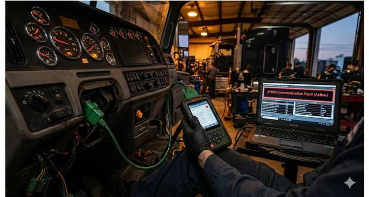
The truck rolls into the bay at quarter past six on a Thursday evening. The driver says the check engine light came on somewhere around mile marker 247 on I-80, stayed on for about forty-five seconds, then went out. The gauges flickered once. The transmission shifted hard for maybe three seconds. Then everything went back to normal. He drove another four hundred miles without incident. Now you have a work order that says intermittent CAN communication fault and a truck that presents perfectly on a static scan. What do you do?
If your shop is like most, someone clears the fault code, road-tests the unit around the block, sees no active codes, and returns it to service. The truck goes back out. Two weeks later it happens again, this time on a Friday afternoon outside Bakersfield with a forty-thousand-pound load of produce that has a delivery deadline. The tow alone costs more than the first diagnostic session. The load delay costs more than the tow. And you still have not fixed the problem.
This pattern is not rare. It is the defining characteristic of intermittent J1939 faults, and over a twelve-month period it pulls roughly eighteen thousand dollars out of the average hundred-vehicle heavy-duty fleet through misdiagnosis, repeat repairs, unnecessary module replacements, towing, and lost revenue. That number climbs as fleet size increases. In a significant percentage of cases, the fix costs nothing in parts and takes roughly thirty minutes. The catch is you have to know exactly where to look and you have to trust a diagnostic method that feels almost too simple to work.
What an Intermittent J1939 Fault Actually Is
The SAE J1939 protocol is the communication backbone every uptime-focused fleet manager needs to understand, even if they never pick up a wrench. It rides on a Controller Area Network physical layer—a twisted shielded pair of wires that carries a differential signal at two hundred fifty kilobits per second, with each end of the backbone closed off by one hundred twenty ohm resistors. Those two resistors in parallel give you a measured sixty ohms across CAN High and CAN Low with the network unpowered. That sixty-ohm reading is not just a number from a spec sheet. It is the single most useful measurement you will ever take on a J1939 network, and it should be the first thing you reach for when communication fault codes start showing up.
A few years ago I put a scope on a J1939 bus in a refuse truck where the telematics module had been spliced in with a stub that ran almost three meters back to the cab corner. The waveform at the engine ECU looked like a canyon echo. The SAE J1939/11 standard sets a one-meter maximum stub length for exactly this reason. Push past it, and signal reflections start eating into the bit edges, making the network jumpy enough to react to tiny voltage shifts. The same standard caps the backbone at forty meters and thirty nodes. Those limits are not suggestions. I have watched one out-of-spec drop line take a perfectly healthy CAN waveform and turn it into a mess that set fault codes on four different modules across four different days. Each time, the code description pointed to a different ECU. Each time, the root cause was that same three-meter stub.
An intermittent J1939 fault is, at its core, a physical layer problem that shows up as a data link error code on whichever ECU happens to be watching the bus at the moment the physical disruption occurs. The fault code you pull with your diagnostic scan tool—whether it is a 639-9 J1939 Network Number 1 Abnormal Update Rate on a Caterpillar engine, an SID 231 FM15 on a Freightliner chassis, or a U0010 on a medium-speed CAN segment—is a symptom. The actual problem lives in the copper, the connectors, or the terminations. It almost never lives inside the modules.
Yet modules get replaced routinely for intermittent J1939 faults. I have watched fleets swap out three ECMs on the same truck for the same recurring communication code before anyone thought to check the firewall bulkhead connector. The modules were never the issue. The issue was a Deutsch connector with a slightly spread socket that made contact when cold and lost contact the moment the engine bay reached operating temperature. The thermal expansion was enough to open the circuit for a few hundred milliseconds at a time—just long enough for the ECU to log a fault and for the driver to catch a split-second gauge dropout.
How One Intermittent Fault Consumes Eighteen Thousand Dollars
Go back to the truck in the opening story. Over a single twelve-month period, that one unit racked up repair costs and downtime that are easy to overlook if your cost accounting system drops each event into a different line item. Let us walk through what actually played out.
The first time the fault set, a technician spent an hour and a half on J1939 diagnostics. The code was historical, not active. The OEM troubleshooting tree directed the tech to check for active codes. Finding none meant the procedure was technically complete. The code was cleared. The truck was released. Diagnostic labor was billed. Two months later the same code came back, and the exact same sequence repeated. That is two diagnostic sessions with zero corrective action.
On the third visit, the shop replaced the engine ECM. The part cost around eight hundred dollars, plus two hundred dollars in labor. The fault returned three weeks later because the module was never defective. The wiring between the ECM and the firewall, however, had a connector terminal with fretting corrosion that opened the CAN Low circuit every time the under-hood temperature climbed past a certain threshold. Nobody looked at it.
Then came the breakdown that mattered. The truck lost J1939 communication entirely fifteen minutes into a delivery run, triggering a derate that left the driver on the shoulder. The tow bill was over six hundred dollars. The load of temperature-sensitive freight spoiled, which became a claim the fleet had to absorb. The customer issued a late-delivery penalty. Dispatch burned two hours re-routing another truck and rescheduling drivers. Industry data consistently shows that the fully loaded cost of an unplanned Class 8 breakdown runs three to five times the direct repair bill once you factor in driver idle time, load loss, customer penalties, and administrative rework. Fleet benchmarks peg unscheduled downtime at four hundred forty-eight to seven hundred sixty dollars per vehicle per day in lost utilization alone—and that does not include towing.
Now multiply this pattern. Studies of fleet maintenance records show that roughly two-thirds of roadside electrical failures had a diagnostic trouble code sitting in the vehicle ECU at least fourteen days before the failure event. The code was there. The truck was in the shop. The opportunity was right in front of them. But the diagnostic process stopped at reading and clearing codes instead of starting there. That is not a technician failure. It is a process failure, driven by service procedures written for active faults that leave no structured path for chasing intermittents.
Add up the wasted diagnostic labor, the unnecessary module replacements, the towing events, the load claims, and the cascading downtime costs across a hundred-truck fleet running Class 8 equipment in regional or long-haul service, and the annual burden of unresolved intermittent J1939 faults settles at roughly eighteen thousand dollars. Some fleets pay more. The number climbs as fleet size increases and as aging equipment racks up more connector wear. But eighteen thousand dollars is a reasonable baseline for a fleet that is not actively hunting these faults with physical-layer diagnostic methods.
Why a Parked Truck Will Fool You Every Time
A multimeter measurement taken with the truck shut off and the harness at ambient temperature will almost never expose an intermittent fault. The resistance across CAN High and CAN Low at the diagnostic connector will read somewhere between fifty-five and sixty-five ohms because both terminating resistors are present and the wiring is continuous in that moment. The voltage differential will show roughly two and a half volts with the network active because the CAN transceivers are driving the bus correctly. Everything looks normal. The technician signs off on the work order. The truck leaves. The fault returns.
What the static measurement misses is what happens when the chassis flexes, when engine torque twists the harness a few degrees, when a connector body expands from heat, or when road vibration causes a pin with reduced normal force to lift off its mating surface for a few milliseconds. None of that can be replicated with the truck parked and the hood open. Those conditions only appear under dynamic load.
I have pulled enough connectors apart on a hot engine to know that the classic failure mechanism in heavy-duty J1939 wiring is fretting corrosion right at the terminal interface.
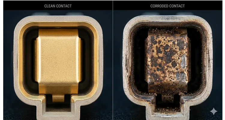
The Deutsch connectors used throughout commercial vehicle wiring are excellent when properly assembled and maintained, but physics still wins over time. Across tens of thousands of thermal cycles and hundreds of thousands of vibration cycles, the tin or gold plating on the terminal pins wears through at the microscopic contact points. Base metal gets exposed. Oxidation forms. The contact resistance creeps up, subtly at first, then more aggressively. That increased resistance generates heat at the contact point, which accelerates oxidation, which further increases resistance, in a feedback loop that eventually creates an open circuit. But the open circuit is not permanent. It opens when the connector is hot and closes when it cools. Or it opens on a particular road surface frequency and closes when the truck changes speed. That is the intermittent fault.
Another common mechanism is terminal back-out. A connector terminal that was not fully seated during harness assembly will stay in contact for months or years until thermal cycling and vibration walk it far enough out of the connector body that the pin no longer fully engages its mate. The circuit becomes sensitive to harness position and movement. Moving the harness during inspection can temporarily restore contact and mask the fault, which is why the truck always behaves perfectly while the technician is looking at it.
A third mechanism is insulation chafing at pinch points. The wiring harness routes through frame rails, around engine mounts, across bulkheads, and past countless metal edges. The protective loom eventually wears through. The insulation on individual conductors abrades against the chassis. A single strand of copper wire begins making intermittent contact with ground, pulling one side of the differential pair toward zero volts in random bursts. The CAN controller sees the bus error and may eventually enter a bus-off state, shutting down communication entirely until the ignition is cycled.
None of these faults will show up on a static resistance check. All of them will reveal themselves under a properly executed wiggle test.
The 30-Minute Wiggle Test: A Step-by-Step Diagnostic Protocol
I first learned the wiggle test from a dog-eared OEM troubleshooting manual in the mid-nineties. The core idea is straightforward: you monitor network parameters in real time while physically manipulating the wiring harness and connectors. When you reach the location of the intermittent fault, the monitored parameter will change. You have found the problem. The repair is then straightforward.
What follows is the protocol I use. It requires a diagnostic scan tool capable of displaying live J1939 data, ideally with the ability to log parameter changes over time. Most professional-grade heavy-duty scan tools support this functionality. Some, like JPRO, include a dedicated wiggle test mode that flags any data point deviating more than ten percent from its baseline value, which is especially useful when you are monitoring multiple parameters simultaneously. A reliable J1939 breakout harness or test adapter that maintains correct impedance and shielding is just as important as the scan tool itself. I often reach for our J1939 9-pin pigtail breakout cable because it gives me a clean access point without disturbing the twisted pair. If your diagnostic cable introduces its own signal reflections or intermittent connections, you will end up chasing phantom faults that do not exist on the vehicle.
Step One: Establish Communication and Baseline
Connect the diagnostic interface to the vehicle diagnostic connector, typically the Deutsch 9-pin connector located in the cab or under the dash. The standard J1939/13 diagnostic connector pinout is as follows, with common failure notes based on field experience:
Pin A | Battery Negative — This pin rarely fails electrically, but the socket can spread if a test light probe was forced in during previous troubleshooting.
Pin B | Battery Positive, unswitched — Corrosion here, often from moisture wicking down the wire from a compromised cab floor seal, can cause a voltage drop that makes the network appear to fail when it is actually starving for power.
Pin C | CAN High, J1939+ — This is the pin where I find fretting corrosion most frequently on the female side, because the smaller terminal has less contact wipe area than the power pins. Look for dark spots or rough texture.
Pin D | CAN Low, J1939- — A backed-out terminal in this cavity will disconnect the differential pair reference for the entire diagnostic connector. If you measure open circuit only on Pin D, start here.
Pin E | CAN Shield — If the shield is broken or disconnected, the network may still function but will become vulnerable to electromagnetic interference that sets faults only when the truck passes a specific radio tower or when the alternator load spikes.
Pin F | SAE J1708+ (legacy) — A short to ground on this line can pull down the entire diagnostic connector voltage if a scan tool is connected, mimicking a J1939 bus failure.
Pin G | SAE J1708- (legacy) — Same failure potential as Pin F.
Pin H | OEM Implement Bus CAN High — If this pin is damaged from a previous improper connection, it can intermittently short to the chassis ground inside the connector body.
Pin J | OEM Implement Bus CAN Low — Same physical vulnerability as Pin H.
Turn the key on and establish communication with the engine ECU and any other modules relevant to the fault you are chasing. Let the network stabilize for approximately sixty seconds. Record the baseline resistance across pins C and D with the key off. You should see approximately sixty ohms, indicating both terminating resistors are present. A reading of one hundred twenty ohms indicates one missing terminator. A reading significantly below fifty ohms indicates a short or an additional unintended termination path. A reading in the megohm range indicates an open circuit somewhere on the backbone.
With the key on, verify that the differential voltage between CAN High and CAN Low is stable at approximately two and a half volts. If the voltage is below one volt, suspect a short to ground on one of the CAN lines. If the voltage is close to battery voltage, suspect a short to power.
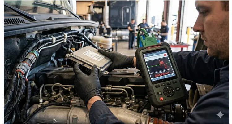
Step Two: Activate Live Monitoring
Open the live data display on your scan tool. The specific parameters you monitor depend on what is available, but at minimum you want to watch the J1939 bus load, which is the percentage of bus capacity currently in use. A healthy J1939 network at two hundred fifty kilobits per second typically runs at thirty to fifty percent bus load. If you see the bus load spiking erratically or dropping to zero, that indicates communication disruption.
Also monitor any parameter that updates continuously, such as engine speed, coolant temperature, or vehicle speed. These serve as canary signals. If the data stream freezes or drops out while you are manipulating the harness, you have located the fault zone.
If your scan tool supports it, monitor fault code status in real time. Some tools allow you to watch whether a specific diagnostic trouble code becomes active or inactive as conditions change. This is the most direct way to correlate physical manipulation with fault occurrence.
Step Three: Systematic Physical Manipulation
This is the step that separates a useful diagnostic session from a wasted one. You must be methodical. Start at one end of the network and work systematically toward the other end. Do not skip around randomly, because if you trigger a fault without knowing exactly which connector or harness segment you were manipulating at that moment, you have gained nothing.
The access points for manipulation vary by vehicle, but the following locations are the most common sources of intermittent J1939 faults, listed in order of probability based on my experience across multiple OEM platforms:
Engine ECU Connectors, P1 and P2: These are the connectors at the engine control module itself. The ECM is typically mounted directly on the engine, which means it experiences full engine vibration and heat cycling. The connector seals can degrade, allowing moisture intrusion. The terminals can fret. Start here.
Firewall Bulkhead Connector: The pass-through connector where the engine harness transitions through the cab firewall is subjected to thermal differential between the engine bay and the cab interior, plus mechanical stress from cab movement relative to the chassis. This is one of the most common failure points I see.
Transmission ECU Connector: Similar environmental exposure to the engine ECU, with the added complication of driveline vibration.
ABS ECU Connector: Often located on the frame rail, exposed to road spray, salt, and physical impact from debris. The connector seals are critical here.
Cab Floor Harness Routing: The section of harness that runs under the floor mat or through the cab floor can be compressed by driver foot pressure, subjected to moisture from wet boots, and pinched by seat mounting bolts if a previous repair was done carelessly.
Dash Cluster and Body Controller Connectors: These are lower-vibration areas but can suffer from connector terminal issues if harnesses were strained during previous dash repairs or accessory installations.
Diagnostic Connector Itself: The Deutsch 9-pin connector in the cab can develop spread pins if a diagnostic tool connector was inserted at an angle or forced, or if an incompatible connector type was used. Note that starting with model year 2016, commercial vehicles began appearing with a green 9-pin diagnostic connector instead of the previous black connector. The green connector is keyed differently to prevent insertion of older tools not rated for five hundred kilobits per second communication speeds. If a technician attempted to force a black connector into a green receptacle, the pins may be damaged.
Each of these connectors should be subjected to the following manipulation sequence: grasp the connector body firmly and apply gentle rocking force in multiple directions while watching the scan tool data. Do not unplug the connector first, because you want to observe the fault while the circuit is energized and under load. If you see a data dropout, a bus load spike, or a fault code going active during manipulation of a particular connector, you have identified the suspect location. Then, and only then, disconnect the connector for visual inspection.
Also manipulate the harness itself. Grasp sections of the harness bundle and flex them, twist them gently, and press on them at the points where they pass through clamps, over frame members, and around corners. Pay particular attention to any area where the harness loom shows signs of chafing, discoloration from heat, or stiffness from contamination.
Step Four: Confirm and Repair
When you have identified the suspect connector or harness section, disconnect it and perform a detailed visual inspection. Look for the following:
Terminal fretting: Dark or discolored spots on the contact surfaces indicate fretting corrosion. Under magnification, you may see pitting or a rough surface texture where the contact should be smooth.
Spread or backed-out terminals: Compare the terminal position and socket opening to a known good terminal of the same type. A spread socket can be identified by inserting the correct male terminal pin and feeling for reduced insertion force or a loose fit.
Damaged connector seals: Torn, missing, or hardened seals allow moisture and contaminants to reach the terminals. Green or white corrosion products on the terminal base are evidence of water intrusion.
Chafed insulation: Where the harness passes over a metal edge, look for the characteristic wear pattern: the outer loom is abraded first, then the conductor insulation, and finally the copper strands are exposed.
Crimp quality: If the terminal is crimped to the wire, inspect the crimp under magnification if possible. A poor crimp will have high resistance from the start and will degrade over time.
Once you have confirmed the fault, the repair is typically straightforward: replace the damaged terminal, replace the connector body if the housing is compromised, clean and reseat a contaminated connection, repair chafed wiring with proper environmental splices, or replace the affected harness section. The specific repair depends on what you find, but the critical point is that you now have a confirmed root cause rather than a guess.
Step Five: Verification
After completing the repair but before releasing the vehicle, repeat the wiggle test at the repaired location to confirm the fault no longer occurs. Clear all diagnostic trouble codes from all modules. Road test the vehicle if possible, monitoring live data throughout the test. Verify that no codes return.
The Three Most Common Mistakes
The first mistake is relying on fault code descriptions to identify the failed component. A J1939 communication fault code tells you which ECU detected the problem and what type of communication failure occurred. It does not tell you where the physical fault is. A code indicating that the engine ECU lost communication with the transmission ECU does not mean the transmission ECU failed. It means the communication path between them was interrupted. The interruption could be at the engine ECU connector, the transmission ECU connector, the terminating resistors, or anywhere along the backbone wiring. Replacing the transmission ECU because the engine ECU reported losing communication with it is the equivalent of replacing your television because the cable signal went out.
The second mistake is performing the wiggle test without live data monitoring. Wiggling connectors and hoping to see something change on the dashboard is not a diagnostic method. The event may be too brief for the gauges to reflect it. You need a scan tool displaying live parameter data that updates at a rate fast enough to capture millisecond-level interruptions. If your scan tool displays data at one-second intervals, you may miss fast transients. Use the fastest update rate available.
The third mistake is failing to check the simple things first. Before spending thirty minutes on a wiggle test, spend five minutes verifying the following: battery voltage at rest and under load, because low system voltage causes CAN transceivers to behave erratically. Ground integrity at the engine-to-chassis ground strap and the cab-to-chassis ground strap, because a floating ground can shift the CAN reference voltage enough to cause bus errors—this J1939 ground offset issue can go undetected for months, silently driving up fleet repair costs. Terminating resistor presence, because a missing terminator causes signal reflections that produce exactly the intermittent symptoms described in this article. These checks take minutes and eliminate the most basic causes.
What Happens When You Fix the Right Problem
A fleet maintenance director I worked with several years ago was dealing with a particular truck that had been to three different dealerships over six months for an intermittent J1939 fault. The truck had received a new engine ECU, a new instrument cluster, and a new wiring harness section between the firewall and the dash. Total parts and labor exceeded seven thousand dollars. The fault persisted.
A technician spent approximately forty-five minutes performing the wiggle test protocol described above. He found that manipulating the engine ECU connector with the engine at operating temperature caused an immediate J1939 communication dropout. Removing the connector revealed a spread terminal in cavity thirty-four, which carries CAN Low on that particular engine platform. The terminal was replaced. The old terminal was examined under magnification and showed classic fretting corrosion on the contact surface. The repair cost less than ten dollars in parts and labor. The fault never returned.
That truck had been out of service for a cumulative total of approximately eleven days across the six months of unresolved faults. Using the conservative downtime cost estimate of four hundred forty-eight dollars per day, the downtime alone cost roughly four thousand nine hundred twenty-eight dollars. Add the unnecessary parts and labor, and that single truck consumed over twelve thousand dollars in avoidable expense before someone performed a focused physical-layer diagnostic procedure that cost almost nothing.
Multiply this story across a fleet, and the eighteen thousand dollar annual figure becomes not just plausible but conservative. The number grows quickly when you consider that the typical fleet averaging two unscheduled breakdowns per vehicle per year, with an average of eight point seven days of unplanned downtime per vehicle annually, is already spending between two hundred eighty thousand and four hundred twenty thousand dollars per year on fully loaded downtime costs across a fifty-vehicle fleet, against a direct repair spend of eighty thousand to one hundred twenty thousand dollars. A meaningful percentage of those breakdowns originate as intermittent electrical faults that were present in the diagnostic history and were not resolved.
What the Harness Remembers
I remember pulling a cab harness from a 2014 Cascadia that had been through three engine overhauls. The main engine harness had been unplugged and replugged so many times that the Deutsch connector locks were worn smooth. The CAN twisted pair was flattened against a coolant pipe where someone had zip-tied it too tight during a previous repair. The protective loom was intact on the outside, so the routing looked acceptable. But the wires inside were compressed into an oval cross-section, and the insulation had cold-flowed to the point where the conductor was within a few thousandths of an inch of shorting to the pipe. That truck had an intermittent J1939 fault logged in its ECM sixteen separate times over two years. Sixteen visits to the shop. No one ever looked at that section of harness.
The wiring harness is the longest continuous component in the vehicle. It contains hundreds of individual circuits subjected to the full range of operating conditions from sub-zero cold starts to desert-grade under-hood temperatures, from highway-speed vibration to off-road shock loading, from dry Arizona air to salted Michigan winter slush. The fact that a thousand individual circuits can survive a decade of Michigan winters and Arizona summers without complaint is a testament to the engineers who designed the system. But even the best design has a service life, and it does degrade.
The J1939 standard specifies a shielded twisted pair cable for a reason. The shielding provides immunity to electromagnetic interference. The twisting ensures that induced noise appears as a common-mode signal that the differential receiver rejects. The termination resistors prevent signal reflection. Every element of the physical layer specification exists because without it, the network does not work reliably. Ignore the physical layer, and you are ignoring the foundation on which every J1939 message depends.
When we build J1939 diagnostic cables and harness assemblies, we build to the same physical layer standards that the vehicle OEMs require. The cable is shielded twisted pair with a characteristic impedance of one hundred twenty ohms and a two hundred fifty kilobit per second data rate capability. The Deutsch connectors are assembled with correctly crimped terminals and verified seal integrity.
We hold a full suite of certifications: ISO 9001, ISO 14001, IATF 16949, RoHS, CE, UL, and REACH. But the one that matters most for connector reliability is IATF 16949. That certification means every batch of crimped terminals goes through a production part approval process where we pull samples and measure pull force, visual contact area, and cross-section voiding under magnification. The reason this matters to your diagnostic work is simple. If you are hunting an intermittent open circuit in a vehicle CAN bus, the last thing you need is a test lead with a loose socket that mimics the exact symptom you are chasing. A diagnostic tool with poor termination or a corroded contact at the diagnostic connector introduces faults that do not exist on the vehicle. That kind of frustration wastes more time than the fault itself.
Every assembly goes through a four-step quality inspection before it leaves the floor. The factory operates under 5S management in a climate-controlled warehouse, because humidity and temperature swings during assembly affect terminal crimp consistency and seal adhesion. We provide OEM customization on every cable we build: logo, branding, cable length, jacket color, conductor gauge, connector type, and pinout configuration. Full plastic design compliant with RoHS standards. Every unit is one hundred percent tested before shipment. This is not above-and-beyond for us. It is the minimum required for a tool you will trust with a diagnosis that might otherwise cost your fleet thousands.
Frequently Asked Questions About Intermittent J1939 Faults
Q: My scan tool keeps pulling a 639-9 code on a Cat engine. Does that mean the ECM is failing?
No. The 639-9 J1939 Network Number 1 Abnormal Update Rate code, like the SID 231 variants on Freightliner and Volvo chassis, or the U0010 on medium-speed CAN segments, simply means one ECU detected that another ECU stopped talking on time. The FMIs you typically see with these are FM12 for bad intelligent device, FM15 for current below normal or open circuit, and FM19 for abnormal update rate. All of them point to a communication disruption. The location of that disruption could be at either ECU connector, anywhere along the backbone, or at the terminators. Do not condemn a module based on these codes alone.
Q: I measured forty-five ohms on a J1939 backbone with everything connected and the key off. Is that close enough, or do I need to track down the problem before the truck leaves?
Track it down now. The specification calls for approximately sixty ohms, which is two one hundred twenty ohm terminating resistors in parallel. A reading of forty-five ohms indicates either a partial short, a third unintended resistive path to ground or power, or a degraded termination resistor. The network may function intermittently at forty-five ohms, but the signal amplitude is reduced and the noise margin is compromised. That truck will set codes again under the right combination of temperature, vibration, and electrical load. Find the extra resistance path before it finds you on the side of the road.
Q: I do not have a scan tool that logs live data. Can I still run a wiggle test with just a multimeter?
You can try, but you will miss fast transients. A multimeter set to resistance can show you an open circuit if you manipulate the harness enough to break the connection completely and hold it there, but an intermittent break that lasts only a few hundred milliseconds will not register on most digital multimeter displays. A scan tool with live data and a fast update rate, ideally twenty milliseconds or better, is the practical minimum for a reliable wiggle test. If a scan tool is not available, an oscilloscope on the CAN lines will capture even the briefest interruption, but that setup takes more time than most bays have.
Q: How long should I budget for a wiggle test when I see an intermittent communication code?
A focused wiggle test targeting the connectors most likely to cause the fault based on which modules are reporting errors should take between twenty and forty-five minutes. If you methodically work through every connector and harness segment on a vehicle with multiple CAN networks and a full body controller, it could take an hour or more. The thirty-minute figure in the title assumes you have already narrowed the suspect list to the engine bus backbone and its primary connectors, which is where the majority of these faults live.
Q: Why does the intermittent fault disappear for weeks at a time and then come back?
The conditions that trigger the fault change. The spread terminal that opens at two hundred degrees Fahrenheit makes perfect contact at one hundred eighty degrees. The chafed wire that grounds out on a specific road surface frequency is fine on smooth pavement. When those conditions stop aligning, the fault stops occurring, but the physical defect has not healed. It will return when the conditions return.
Q: Are modules ever the real cause of an intermittent J1939 fault?
Yes, but far less often than wiring and connectors. A failed CAN transceiver inside an ECU can generate intermittent bus errors, but by the time that happens, the module usually has other symptoms, like failing to wake up consistently or refusing to accept a parameter reset. Start with the physical layer. It is the most probable cause and the easiest to verify. If the wiring, connectors, and terminations check out completely after a thorough wiggle test and a scope check, then module-level diagnosis is the appropriate next step.
Q: My shop has both black and green 9-pin diagnostic connectors on different trucks. What is the difference and why does it matter for my test equipment?
The black connector is the original 9-pin Deutsch diagnostic connector defined in SAE J1939/13, used on vehicles built before approximately 2016. The green connector, introduced starting with model year 2016, is keyed differently to physically reject older diagnostic connectors. The change happened because newer vehicles began supporting five hundred kilobit per second CAN communication, and plugging an incompatible tool into the network risked damaging either the tool or the vehicle nodes. The green connector is backward compatible for properly designed scan tool adapters, but it will not accept legacy hardware. If someone jammed a black connector into a green receptacle, inspect those pins before you do anything else.
Q: I ran the wiggle test for an hour and found nothing, but the truck still sets codes intermittently. What is my next move?
Expand the investigation beyond mechanical manipulation. Connect an oscilloscope to the CAN lines and look at the waveform under different operating conditions. Excessive ringing on the bit edges suggests a termination or impedance problem. Slow rise and fall times suggest excess capacitance, often from a module that is still functioning but has degraded internal components. Dropouts that only occur when an electrical load switches on, like the cooling fan or the grid heater, suggest an electromagnetic interference source. Review the freeze frame data if the ECU captured it. A pattern like the fault always setting at a particular engine RPM, road speed, or coolant temperature will guide you to a condition you can replicate in the bay.
Q: What is the single biggest prevention step I can take to reduce intermittent J1939 faults across my fleet?
Respect the harness during every repair. Never pull on the wires to disconnect a connector. Use the connector body. Inspect seals before reassembly and replace any that are torn or hardened. Route harnesses with clearance from hot surfaces, sharp edges, and moving parts. Never, under any circumstance, tap into CAN wiring with scotch-lock connectors or insulation-displacement methods. Use the proper Y-cables or pass-through adapters that maintain the network impedance. The wiring harness is not a consumable, but it is also not immortal. Treat it like the precision component it is.
Q: At what point does it make more sense to replace an entire harness section rather than repair individual terminals?
Replace the harness or a harness section when you find multiple compromised terminals in the same connector, widespread corrosion that has wicked up the wire strands beyond the terminal barrel, insulation that is cracked and brittle across multiple circuits, or a harness that already has more splices than original conductor. Every splice is a future failure point. In a fleet where unscheduled downtime costs hundreds of dollars per day, the price of a new harness section is frequently less than the accumulated cost of chasing a series of cascading failures in an aging assembly that has already told you it is tired.
If you are sourcing J1939 diagnostic cables, adapters, or custom wiring harness assemblies for fleet maintenance or OEM integration, and you need a manufacturing partner that builds to SAE physical layer specifications with full traceability and certification, we should talk. Our engineering team provides direct technical support for OEM customization projects, including pinout configuration, connector selection, wire gauge specification, and branding. Reach out on WhatsApp for a direct conversation with an engineer who understands J1939 from the bit level up, or use the contact form on our website to submit your specifications. We respond with technical answers, not sales scripts.
Contact Page: https://obd-cable.com/contact/
