

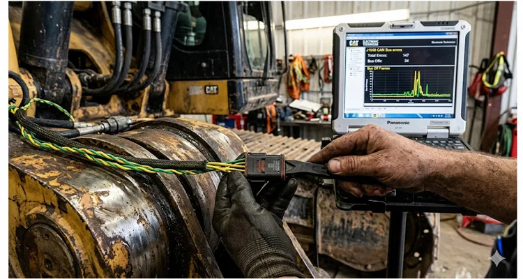
An intermittent J1939 open laughs at a bench multimeter. I’ve been on my back under a paving machine in the Texas heat, staring at a J1939 harness that looked fine, while the ECU logged CAN communication errors I couldn’t force to repeat. The operator said the transmission would drop into neutral for two seconds, only on rough ground. I’ve measured 0.2 Ω on a harness at rest that opened to 6 kΩ the moment the paver’s articulation hit 22 degrees. That machine eventually cost us three weeks of guessing. The culprit? A single fractured wire inside perfect-looking insulation, right where the harness flexed near the articulation joint.
That’s not a measurement problem; it’s a test condition problem. The wiggle test protocol gives you a way to move the fault condition into the shop instead of waiting for the machine to break again on the haul road. I’ve used this systematic diagnostic protocol on dozers, combines, drill rigs, and haul trucks, and it consistently reduces diagnostic time from “throw parts at it” to a few focused hours with the right tools. The technique draws on the same principles of electrical continuity testing that field technicians have relied on for decades, but applies them dynamically rather than statically.
A Wiggle Test Isn’t a First Step
A systematic wiggle test isn’t a first step. If you’ve already found a hard short to ground, you don’t need a wiggle test — stop here and meter the pins. This diagnostic protocol only earns its place when you can tick off all four of these conditions:
- Fault logs show sporadic FMI 2 (Data Erratic), FMI 9 (Abnormal Update Rate), or FMI 12 (Bad Intelligent Device) on multiple ECUs, but you can’t reproduce the fault statically.
- Your machine shows intermittent CAN communication loss only under specific mechanical conditions: high vibration, articulation turns, a particular engine RPM band, or thermal soak after a hot shutdown.
- You’ve already verified the J1939 terminating resistors are within spec — that’s 120 ohms across pins C and D at the diagnostic port with the system asleep, not 180 ohms, not 90 ohms.
- The intermittent J1939 fault is clearly momentary — the machine recovers on its own, and the error counter in your diagnostic tool shows active errors that clear after a key cycle.
Before you even pick up a pry tool, take sixty seconds and swap the suspect ECU with a known-good unit, or run a discrete power supply test. A weak voltage regulator inside an ECU can drop the CAN transceiver offline momentarily under vibration, perfectly mimicking a harness open. If the error counters follow the ECU, the fault is internal. If they stay with the harness location, proceed with the wiggle protocol. This ECU substitution test should always precede any harness diagnosis.
A 2018 Cat 966M I worked on would drop the transmission ECU only during a loaded right turn with the bucket below 1.2 m. We eventually found the green CAN-H wire had cold-worked just past the cab-side clamp, where the bend radius was less than 60 mm. At full articulation, the insulation stretched 0.8 mm while the copper strands slipped apart. That’s the kind of intermittent open this wiggle test protocol is built to find.
Why the Wire Fails Before You Can See It
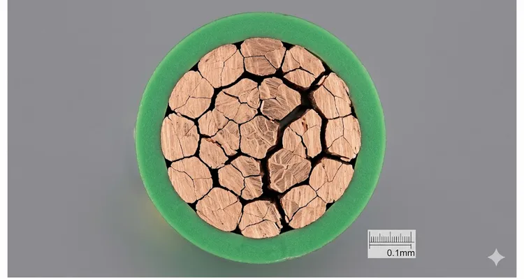
The Copper Fracture Mechanism
I’ve sectioned J1939 harnesses that measured a clean 60 Ω end-to-end on the workbench but still failed with intermittent opens on the machine. Under the insulation, the copper wasn’t missing — it was a chain of fractured grains held in contact by the insulation’s compression. Once the harness bends, those grains separate enough to spike the local impedance by 30–40 Ω, which the transmitter reads as a signal reflection. You can’t fix that with solder and heat-shrink. This is work hardening at the microscopic level, invisible to a standard continuity test. The cross-section below shows exactly what a standard continuity test misses.
If you want a deeper technical breakdown of what happens at the waveform level when this occurs, our J1939 waveform analysis guide walks through capturing these reflections with a 200 MHz USB scope.
Signal Behavior During an Open Circuit
Inside a J1939 CAN backbone, the 120-ohm twisted pair (yellow CAN-H, green CAN-L) carries a differential signal. When an intermittent open occurs along that backbone, the signal doesn’t just vanish — it reflects, setting up a standing wave that corrupts the next message. One ECU may still see the data, but the one past the break doesn’t. This is why you’ll see a “missing message” fault on the engine ECU, while the transmission ECU still shows active, depending on where the break sits relative to the terminating resistor. Understanding these signal reflections is key to interpreting your wiggle test results. For guidance on the physical-layer checks that complement the wiggle test, including the 60-ohm measurement and waveform validation, see our J1939 physical layer troubleshooting walkthrough.
Thermal Expansion and Connector Back-Out
Thermal expansion complicates this further. A Deutsch connector that’s tight when warm can become an open circuit when cold-shrunk by just 0.2 mm. I’ve logged intermittent J1939 failures that only appeared during the first 10 minutes of a winter morning, then vanished once the harness warmed up. That’s a classic sign of a pin backing out of the connector body just enough to lose contact. This is why your wiggle test needs to account for ambient temperature and not just mechanical vibration. This same connector degradation mechanism often contributes to J1939 ground offset issues across fleets, as detailed in our ground offset fleet cost analysis.
The Wiggle Test Protocol, Step by Step
To run a proper wiggle test, you need a diagnostic interface that reads J1939 error counters in real time — not just a code reader that pulls stored DTCs. My own diagnostic setup overlays active DM1 messages with live CAN bus traffic. A break-out box between the suspect ECU and its 9-pin or Deutsch connector saves time; you can also back-probe carefully on sealed connectors. Never pierce the insulation. This real-time monitoring rig turns the wiggle test from a guessing game into a precision diagnostic method. For direct access to the CAN lines without cutting into the harness, many techs use a J1939 9-pin pigtail breakout cable that brings CAN_H, CAN_L, and power to labeled test points while the bus stays live.
- Map the J1939 CAN backbone by failure history, not the wiring schematic. I start at the diagnostic resistor and follow the twisted pair toward the highest-failure zone: articulation joints, then bulkhead pass-throughs with hard plastic edge guards, then any point where a zip tie has been cinched with pliers. If the cable jacket shows a polished line, it’s been moving against metal. Mark those spots with a white marker — they’re your first wiggle points.
- Divide the J1939 network. Use the deployment of the terminating resistors. If you have access to the center of the CAN backbone — often at the diagnostic connector — you can split the network into front and rear halves. Disconnect ECUs on one half and monitor the error rate on the still-connected segment. This physical segmentation tells you exactly which side contains the intermittent open.
- Set up real-time CAN monitoring. Connect your scan tool and graph the “Bus Off” or “Passive Error” frame. If your tool can log at 100 ms intervals, even better. You want to capture the exact moment the error count increments. This real-time data is what makes the wiggle test a precision diagnostic rather than a crude physical check. For a practical breakdown of which signals to watch and why, the J1939 data link error diagnosis guide outlines how to isolate faults within 20 minutes using these same real-time counters.
- Apply controlled mechanical stress — the core of the wiggle test protocol. Don’t wiggle randomly. Use a non-conductive plastic pry tool. Start at the connector body of the suspect ECU. Wiggle the connector sideways gently — 2–3 mm of deflection is plenty. Watch your error counter. Move down the harness 10 cm at a time, applying the same lateral force. When you find the zone where the error count spikes, you’ve localized the intermittent open to within a few inches. A spike in the error counter while you deflect a connector often means you are looking at a J1939 bit sampling error, where a reflection corrupts a single bit and pushes the transceiver briefly into a Bus Off state — a failure mode explained further in our bit sampling error analysis.
- Audit every CAN splice. If the machine has a factory or field-installed CAN splice — solder-and-heat-shrink or a sealed junction block — spend extra time there. I’ve found more intermittent opens in aftermarket telematics splices than anywhere else. A poorly executed splice is a guaranteed failure point on any J1939 harness.
Five Ways to Fool Yourself During a Wiggle Test
I’ve committed every one of these errors at least once in the field. Avoiding them will save you half a shift.
- Wiggling too aggressively during the test. If you yank the harness hard enough to generate a fault even on healthy wire, you’ll spend an hour chasing a phantom break. Gentle lateral pressure reveals real weak points without creating new ones. The wiggle test is about precision, not force.
- Overlooking a failing J1939 terminating resistor. An intermittent open inside a molded terminating resistor cap can mimic a CAN backbone open perfectly. Test the resistor while tapping it lightly with a screwdriver handle. A failing terminating resistor produces identical symptoms to a harness open. For more on how subtle termination mistakes can drive up repair costs, see our J1939 termination mistakes cost analysis.
- Trusting a visual inspection of the harness. I’ve cut open harnesses where the copper looked continuous but was actually a collection of individual fractured strands held together by the insulation’s memory. If the wiggle test points to a spot, replace that section of wire — don’t just tape it. Visual confirmation is worthless without electrical validation.
- Blaming the harness before ruling out ECU internal faults. A weak voltage regulator inside an ECU can drop the CAN transceiver offline momentarily under vibration. Swap the suspect ECU to a known-good machine or run a discrete power supply test before condemning the J1939 harness. For a real-world case where a controller was still partially communicating despite a failing transceiver, refer to our J1939 transceiver failure analysis.
- Forgetting the CAN shield drain wire continuity. A broken shield termination creates a floating ground reference that can induce CAN bus noise, making the bus go intermittent without a true open circuit. Check continuity of the CAN shield to battery ground at both ends. A grounding issue can perfectly mimic an intermittent open during your wiggle test. We cover the diagnostic steps for isolating this exact condition in our J1939 ground offset diagnosis guide.
How to Know You Truly Fixed the Intermittent J1939 Open
After you’ve repaired the intermittent open — whether you replaced a backed-out pin, a fatigued wire section, or an entire pigtail — the real proof comes from mechanical repetition. Clear all DTCs. Start the machine and run the operation that previously triggered the fault at least 15 times. If it was an articulation-related break, cycle the steering lock-to-lock under load repeatedly. One clean key cycle isn’t enough; the intermittent open must be proven gone across multiple duty cycles.
I also monitor the J1939 error counters for a 30-minute duty cycle post-repair. A properly functioning high-speed CAN bus should show zero transmit error counts and zero receive error counts. If you see even a single passive error frame increment, you haven’t found all the damage. Go back and check the other leg of the CAN backbone — sometimes the initial break causes enough pulling force to partially damage another wire in the same harness bundle. A thorough post-repair validation is what separates a permanent fix from a callback.
Diagnostic Cables That Support a Rigorous Wiggle Test Protocol
Every wiggle test depends on a diagnostic adapter and cable set that won’t create its own intermittent connection. Our engineering team designs diagnostic cable assemblies to endure exactly the field stress I’ve been describing — overmolded connectors with a PVC jacket that resist the flex fatigue at the heart of so many J1939 opens. A diagnostic cable that fails during a wiggle test will send you down false paths for hours. The materials we select draw from established wire rope and cable construction principles that govern how stranded conductors behave under cyclic bending loads — the same physics that determines whether a harness survives 1,000 or 100,000 machine hours.
Overmold Design Engineered for Flex Fatigue Resistance
The diagnostic cables we ship are overmolded with a PVC compound that we’ve tested through 200,000 flex cycles at –30 °C — the same motion that causes the work-hardening breaks I described earlier. Instead of a standard strain relief, the overmold extends 45 mm past the rear of the connector, distributing the bend along a longer arc. That’s not marketing; it’s a direct answer to a joint failure we traced in a customer’s 24-volt CAN backbone three years ago. We duplicate the OEM pinout for Cat, John Deere, Volvo, and Komatsu equipment as a standard offering, and all materials meet RoHS and REACH standards under our ISO 9001 and IATF 16949 quality systems. For technical buyers who want to compare connector series and their impact on maintenance budgets, our Deutsch connector series selection guide provides a detailed breakdown of options and lifetime cost considerations.
Our manufacturing facility operates under a fully integrated quality and environmental management system, holding certifications to GB/T 19001-2016/ISO 9001:2015 for quality management and GB/T 24001-2016/ISO 14001:2015 for environmental management. These certifications ensure that every diagnostic cable assembly is produced under tightly controlled processes with full material traceability, from incoming quality control (IQC) through to final continuity and load testing. In May 2025, we further solidified our commitment to the automotive supply chain by achieving IATF 16949:2016 certification — the global benchmark for quality management in automotive production, which emphasizes defect prevention, risk management, and continuous improvement across every production batch. Every diagnostic cable assembly undergoes 4-step inline continuity testing before it leaves the factory floor.
Custom Harness Replication for Legacy Heavy Equipment
If you’re dealing with a proprietary harness that’s no longer available from the OEM, we can duplicate the original assembly — same AWG, same color coding, same connector orientation — typically within a few weeks, with engineering support from the initial drawing check through to final sample approval. Whether you need a single replacement harness or a fleet-wide solution, we match the original routing, bend radii, and strain-relief dimensions exactly.
Frequently Asked Questions About the Wiggle Test Protocol
How long should a J1939 wiggle test take on a standard off-highway machine?
On a tractor or single articulated hauler, a focused harness wiggle test with real-time monitoring should localize the intermittent open within 3–4 hours. On larger units like a mining shovel with multiple junction boxes, plan for a full day. The diagnostic time depends on harness accessibility and how many ECUs share the J1939 backbone.
Can I perform a wiggle test without a real-time CAN bus monitor?
You can use a multimeter on the resistance setting and watch for a break in continuity, but you’ll miss split-second opens. The meter isn’t fast enough to catch a 50-millisecond disconnection caused by vibration. A CAN monitor with real-time error counter display is the more reliable witness for an intermittent J1939 open.
What’s the acceptable J1939 termination resistance range I should see during the wiggle test?
A healthy, unpowered J1939 backbone will read between 55 and 65 Ω at the diagnostic connector. If the meter holds steady at 120 Ω, you’ve lost one terminating resistor or its feed wire. But don’t stop there. If the value drifts between 70 and 110 Ω while a second technician rocks the machine, you’re seeing the effect of a high-resistance open that’s still partially connected — exactly the condition the wiggle test traps. For a complete reference on normal voltage ranges for CAN-H and CAN-L in a healthy network, see our J1939 voltage range specification.
Will a broken CAN shield wire cause an intermittent open?
It causes noise-induced errors, not a true open circuit. The bus may go offline when the alternator or hydraulic solenoid kicks in, making it look intermittent. Testing shield continuity from the CAN shield to battery ground at both ends is part of the full wiggle test protocol.
Does the wiggle test work for CAN FD and CAN 2.0B as well?
The physical layer principles are identical. The wiggle protocol works on any CAN variant running over J1939-style twisted pair. The higher bit rates of CAN FD make it more sensitive to impedance mismatches, so your wiggle test might actually catch marginal wiring even faster than on standard J1939.
What if the intermittent J1939 fault only occurs when the machine is covered in mud?
Weight and cooling effect. Wet mud adds mass that can pull on improperly supported harness sections, and it also cools the connector, causing thermal contraction. Simulate the condition by washing the suspect area and then monitoring during the rapid temperature drop. This field-expedient diagnostic trick has helped me replicate mud-only intermittent opens.
Our fleet has recurring J1939 opens near the DEF tank. What should we check?
DEF crystals can wick up the harness and corrode copper inside the insulation, creating a high-resistance path that eventually opens into an intermittent open. Inspect the sealing plug of every connector near the DEF system; any green crust means the wire is compromised further inside the harness. This is a common J1939 failure mode on Tier 4 Final machines that I’ve seen across multiple fleet operations.
Can you build a replacement harness that exactly matches the routing of our current machine?
Yes. We replicate legacy harnesses sample-by-sample. We pull dimensions, branch lengths, and connector clocking from your original, or from a CAD drawing if you have one. No re-engineering of the harness routing required. This OEM-spec duplication service covers everything from AWG selection to overmold geometry.
How do I know if the fault is in the harness or inside an ECU?
Swap the suspect ECU with a known-good unit before running the wiggle test. If the error counters follow the ECU, the fault is internal. If they stay with the harness location, proceed with the wiggle protocol. This ECU substitution test should always precede any harness diagnosis.
What’s the most overlooked cause of intermittent J1939 opens in articulated equipment?
The bulkhead connector at the articulation point. I’ve found more intermittent opens there than anywhere else on articulated haul trucks and wheel loaders. The connector may test fine at rest, but under full articulation, the internal pins lose contact by fractions of a millimeter. Always start your wiggle test at the articulation joint.
Diagnostic Cables & Harness Support for Your Fleet
We work directly with fleet maintenance teams who need J1939 harness solutions built to match the machine’s actual routing and flex points — not a generic off-the-shelf cable. If you’re diagnosing a recurring intermittent J1939 open and considering a harness retrofit, we can discuss the exact connector series, AWG, and overmold requirements. For teams looking for a step-by-step troubleshooting framework that complements the wiggle test, we’ve also published a dedicated guide on intermittent J1939 faults and the wiggle test.
→ Submit a Drawing or Inquiry: https://obd-cable.com/contact/
→ Message on WhatsApp: https://api.whatsapp.com/send/?phone=8617307168662&text=Need+Help%3F+Chat+linda+WhatsAPP&type=phone_number&app_absent=0
When you send us a sample harness, we return a CAD drawing with bend radii, strain-relief dimensions, and the exact Deutsch pin orientation before we cut the first wire. That’s the engineering support that comes with every build. Direct factory technical team, ISO 9001 and IATF 16949 certified, with 20+ years of heavy equipment harness manufacturing experience.
