

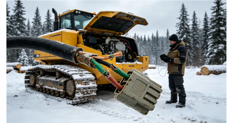
Last February I stood knee-deep in snow next to a tracked feller-buncher in northern Quebec. The operator had limped the machine to the edge of the cut block after it derated for the fourth time that week. The engine ECU was throwing SPN 639 FMI 9 — Abnormal Update Rate on the J1939 datalink — and the local dealer had already swapped the engine controller and the display. The real problem was buried under a wad of electrical tape near the articulation joint: a section of CAN harness where the jacket had been worn through by a steel bracket. The twisted pair was visible, green with corrosion, and one of the conductors had fractured inside the insulation.
That single harness failure cost the contractor over two thousand dollars in emergency field service, plus another sixteen hundred in lost production. Over the course of a season, three near-identical incidents on three machines added up to just under eight thousand dollars in completely avoidable field repairs. Multiply that across a fleet of forwarders, harvesters, or skidders, and the number becomes a quiet budget drain nobody mentions at the monthly maintenance meeting — until someone finally asks why machine availability is stuck at eighty-two percent.
I’ve spent more than twenty years untangling J1939 networks on logging equipment, first on the diagnostic side and later right on the harness manufacturing floor. What follows isn’t a marketing deck. It’s an engineer’s field-level view of why forestry J1939 failures are overwhelmingly harness-driven, how a properly built harness rewrites the cost equation, and what you can do the next time your CAN bus parks a six-figure machine in limp mode because of a ten-dollar connector.
The forest isn’t a highway — why the standard harness fails
A J1939 backbone on a highway tractor is a predictable animal: 250 kbps, forty meters of ladder frame, clean terminations, no surprises. Drag that same twisted pair through the articulation knuckle of a forwarder — where the bend radius compresses with every turn and the ambient temperature cycles from minus forty overnight to plus eighty under the hood — and the 120-ohm impedance you banked on starts drifting before lunch. I’ve written about this exact impedance-to-cost chain before: a J1939 backbone designed without headroom for 60-ohm tolerance will derate a machine long before any dashboard lamp tells the operator what’s actually failing. Once the differential signal softens, you’re chasing network ghosts that the standard diagnostic tree was never written to catch.
Inside a harvester or forwarder, the J1939 backbone snakes through compartments that get pressure-washed twice a day, past hydraulic valve banks that sit at 180 degrees Fahrenheit, and across articulation joints that rotate through ninety degrees in deep ruts. Wood debris packs into every crevice. Urea-based hydraulic fluids eat at connector seals. I’ve yet to see a lab test that replicates the corrosion cell you get when an unsealed connector endures a hundred freeze-thaw cycles with wet wood fiber packed against the seal — that’s the real-world chemistry that starts the clock on a network fault.
The typical production harness on a mid-tier forestry machine is built to a cost target, not a survival spec. You’ll find 20 AWG tinned copper conductors, PVC insulation, and unsealed Metri-Pack connectors everywhere. PVC turns brittle below minus twenty. Unsealed connectors pull moisture straight into the crimp zone by capillary action. When a pin corrodes, the resistance climb disrupts the differential impedance of the CAN bus, generating random bit errors. The ECU interprets those as intermittent message timeouts and logs a network fault. The technician, standing in the rain with a laptop, swaps the ECU — because that’s the path the diagnostic tree sends him down — and the fault walks back in three weeks later.
How one harness change eliminates half a dozen failure modes
Let’s walk a real diagnostic sequence I followed on that Quebec machine, then compare it to what a purpose-built J1939 forestry harness would have done on day one.
Step 1: Resistance measurement at the 9-pin diagnostic connector
Measure the bus before you disturb anything. With the machine shut down, key off, battery disconnect open, I took a resistance between CAN H and CAN L reading at the 9-pin diagnostic connector. The meter showed 123 ohms. A healthy J1939 backbone must read 60 ohms — two 120-ohm termination resistors in parallel across the bus. That number told me instantly that one termination resistor had dropped out of circuit, almost certainly because a conductor had broken somewhere between a backbone stub and the main trunk.
Step 2: Termination resistor location verification
The OEM wiring diagram placed one terminator inside the engine ECU connector and the second inside a weatherproof cap near the rear frame harness. The rear resistor itself was intact but showed no continuity to the bus. Back-probing along the harness with a fine probe located the open circuit roughly eighteen inches forward of the articulation point.
Step 3: Physical inspection under full articulation
With the machine articulated hard left, the harness at the pivot had been pulled tight against a sharp bracket. The outer nylon jacket was sliced through, the foil shield torn open, and the green CAN-H conductor severed internally while the insulation looked unbroken — a textbook “green stick” fracture from work-hardening.
Now consider what a purpose-built J1939 forestry harness would have looked like in that same location. A harvester OEM once asked us to re-engineer the boom-tip harness after three warranty returns from Finnish Lapland. We knew the failure mode before we cut open the first sample: 7-strand conductors had work-hardened and snapped inside intact insulation. The replacement we built used 20 AWG 19-strand tinned copper to take the flex cycles without micro-cracking, cross-linked polyethylene (XLPE) insulation rated from minus forty to two hundred seventy-five degrees Fahrenheit, and a true one-twist-per-inch pair inside aluminum-polyester foil with a tinned drain wire landed only at the ECU ground stud — because anything else invites a ground loop that eats your noise margin. Every connector was Deutsch DT with gold-plated nickel contacts and integrated interfacial seals; the connector bodies were glass-filled polyamide that stays ductile in subzero weather. At the articulation pivot, we added moulded polyurethane boots and spiral-cut abrasion sleeve held in place by Tefzel clamps that won’t cut the jacket. That forestry harness has not failed in two full winter seasons. If you’re specifying connectors for articulation zones, the choice between Deutsch DT vs. HD series directly shapes your maintenance budget, and getting it wrong means replacing connectors in the field instead of running production.
Apply that same material logic to the Quebec feller-buncher and the whole failure chain disappears. No moisture ingress, no work-hardened fracture, no bus impedance shift, no intermittent network fault, no derate, no service call. The gap between a harness that trims a few cents on a purchase order and one that wipes out thousands of dollars in downstream cost comes down to a handful of material decisions that somebody either understands — or ignores.
The eight thousand dollars a year math — where the money actually leaks
Most contractors never add up field repair costs as a single line item; the numbers are scattered across labour, parts, travel, and lost production. The breakdown below comes from actual service records I’ve reviewed across logging operations in eastern Canada and the U.S. South, including a tracked feller-buncher working mixed spruce-fir stands in the Gaspé:
- Mobile field technician call-out, portal-to-portal: four hours at one hundred eighty dollars per hour — seven hundred twenty dollars.
- Emergency parts delivery: two hundred fifty dollars (connector kit, replacement sensor if a voltage spike occurred).
- Machine downtime: a feller-buncher cutting a hundred tons per day at a stumpage-to-delivered margin of twelve dollars per ton loses one thousand two hundred dollars of contribution margin per eight-hour shift. When the fault hits mid-morning and the machine sits for six hours, that’s nine hundred dollars in lost production you never get back.
- Total per incident: roughly two thousand one hundred seventy dollars.
Four such incidents per year across a small fleet of three to five machines is eight thousand six hundred eighty dollars. The right harness — designed, tested, and validated for the application — drives those incidents to near zero. Even a conservative seventy-five-percent reduction puts the net annual saving between six thousand five hundred and eight thousand dollars. That’s not spreadsheet theory. That’s what happens when a logging outfit swaps the factory cable for something designed by people who understand CAN physical layer as well as they understand what a harvester head endures in a spruce stand. We’ve documented how physical-layer troubleshooting with basic tools can cut downtime by seventy percent — a number that lines up squarely with the field data above.
What to look for when you specify a replacement harness
If you’re an equipment OEM or a fleet manager tired of chasing intermittent J1939 faults, here is the engineering checklist I use when I review a harness design for forestry. Every line is tied to a failure I’ve physically pulled out of a machine. For the complete protection strategies we apply in these environments, I’ve detailed them separately in our J1939 harness protection guide for forestry equipment.
- Wire stranding near articulation zones: we’ve watched 7-strand conductors work-harden and snap inside intact insulation at 3,200 machine hours on Ponsse Scorpions. 19-strand copper handles the same duty cycle without micro-cracking. For CAN runs up to forty meters, stick with 20 AWG 19/32 stranding; power circuits to remote terminators need 18 AWG minimum.
- Twist rate: one complete twist per twenty-five to fifty millimetres. A lazy twist kills noise rejection. On a Tigercat 630C working Oregon coastal brush, opening the twist to add a service loop introduced enough signal reflection to take the bus down once a week.
- Connector sealing: IP67 minimum at every join. Field experience shows IP67 survives pressure washing as long as connectors are fully mated and locked. We’ve drained water from IP65 connectors on forwarders after a single season of twice-daily washdowns.
- Terminal plating: gold flash over nickel. Pure tin terminals are a false economy on any machine that sees condensation cycles. I’ve measured an 8-ohm resistance drift on tin terminals inside a supposedly sealed bulkhead connector after eighteen months in northern Alberta.
- Termination resistors: integrate them into sealed connector caps, never as field-installed splices. A resistor buried inside a heatshrink tube is a failure waiting to happen — I’ve found three in the last two years that corroded open because moisture crept past the adhesive lining. On a cold morning, the drift you’ll measure between a hot vs. cold termination resistor can be enough to push a marginal bus over the edge before the engine even reaches operating temperature.
- Abrasion protection: heavy-duty polyurethane tubing or self-wrapping split braid wherever the harness passes within fifty millimetres of a moving part or steel edge. On a stroke delimber, the tail-section harness was chafed through to the shield in 1,100 hours because the OEM used a simple nylon sleeve that trapped grit.
- Documentation: a pin-to-pin wiring table, connector face views, and a physical routing drawing with clamping locations. Without these, field troubleshooting is pure guesswork. I’ve burned hours tracing wires on a used forwarder because the previous owner had no schematic — that’s downtime nobody ever budgets for.
Common mistakes that cost more than a new harness
Over the years I’ve seen well-intentioned field repairs turn small problems into major ones:
- Cutting and splicing the CAN bus to “add a service loop” without preserving twist rate or shield integrity. On a forwarder in New Brunswick, this introduced signal reflections that showed up as overshoot on a PicoScope, and the transmission controller began dropping into neutral at random. The splice had been in place for three days. A wiggle-test protocol for J1939 harness opens would have caught the intermittent break before it became a transmission-neutral event on a slope.
- Replacing one terminator resistor with a single 60-ohm resistor because the technician misread the bus resistance. A 60-ohm load does not replace two 120-ohm terminations correctly and distorts bus voltage levels. The machine ran for a week before the engine ECU started logging sporadic address claim failures.
- Using unsealed butt connectors with heat-shrink that eventually wicks water along the conductor strands. Black-wire corrosion travelled over a meter inside the insulation before the CAN-H line opened. The fault only appeared at operating temperature, after the harness expanded enough to separate the corroded strands.
- Wrapping damaged jacket with electrical tape and walking away. The machine ran four days before a rainstorm. Water pooled in the taped section, the CAN-H line shorted to chassis ground at full throttle, and the transmission controller defaulted to neutral — on a thirty-percent grade.
Each of these “fixes” buys a few days of runtime and sets up a much more expensive failure down the road. I’ve walked through the diagnostic workflow for exactly this kind of J1939 calibration fault troubleshooting before — spoiler: the flowchart almost always dead-ends at the harness physical layer when the fault is intermittent.
Verifying the repair after installing the right harness
Commissioning a replacement harness is never a checkbox exercise. The sequence is methodical, but I’ve added my own hard-won habits to it. I carry a dedicated Fluke 87V with gold-plated probes just for the 60-ohm test — standard probes add enough contact resistance to introduce a 0.5-ohm error that can mask a weak terminator. On a John Deere 853M, I take the resistance reading at the 9-pin, then again at the engine ECU connector with the rear terminator cap removed, because I’ve found water sitting inside that dummy cap on two separate machines in coastal BC.
Resistance check: 60 ohms ± 2 ohms between CAN H and CAN L
60 ohms ± 2 ohms between CAN H and CAN L at the diagnostic connector, key off. Infinite resistance to ground and to battery positive. If I see 61.5 ohms, I don’t walk away — I track down which terminator has a weak crimp.
Bus voltage check: CAN H at 2.7 V, CAN L at 2.3 V key-on engine-off
Key on, engine off — CAN H should sit around 2.7 volts, CAN L around 2.3 volts, with less than 0.1 volt difference between nodes measured at the furthest connector. A reading of 3.1 volts on CAN H with a warm engine that collapses to 1.9 volts on cold start almost always points to a resistive short to battery voltage that only makes contact once the harness expands with heat.
Signal quality test: PicoScope capture of CAN waveforms
PicoScope across the bus, grabbing a burst of messages. I’m looking for clean square waveforms with minimal overshoot, no clipping, and a crisp recessive-to-dominant transition. A single reflection spike tells me there’s an impedance discontinuity somewhere along the backbone. If you’re new to interpreting what healthy CAN waveforms should look like, I’ve published a practical guide to J1939 scope bench measurements covering edge rates, ringing, and differential voltage that walks through each parameter.
Dynamic test: error frame count under full hydraulic cycling
With the machine running and every hydraulic function cycled, I watch error frame counts on a J1939 monitor tool. Any jump during articulation, throttle snaps, or hammer operation flags an intermittent open or short that hasn’t been caught yet. I once found a loose pin in a bulkhead connector solely because the error frame count spiked by six counts the moment the harvester head tilted past seventy degrees.
Visual final inspection of connectors and routing
Check every connector backshell is sealed, every label legible, every tie-wrap flush-cut so it can’t slice the harness outer layer over time. I’ve seen a zip tie tail cut through a silicone jacket in under 500 hours.
If all steps pass, the network is stable. On the machines I’ve followed up at six and twelve months, a forestry CAN harness built to this standard has logged zero repeat network faults. Zero.
Where factory process makes the difference
A forestry harness is not a bench project; it’s a production component that must repeat across hundreds of units. When I walk our wire harness factory floor during a supplier audit, I’m not looking for glossy presentation. I’m watching how the team manages humidity, contamination, and inspection discipline.
After a batch of harnesses in 2021 showed intermittent CAN faults traced to terminal fretting, we pulled humidity sensors into the crimping area and discovered the air conditioning condensate drain was pushing local relative humidity to seventy-two percent for about three hours every morning. We added a desiccant dehumidifier circuit, brought the zone down to a steady forty-five percent RH, and introduced a hipot test step that checks every circuit at one thousand five hundred volts DC. Since that change, our warranty return rate on forestry CAN harnesses has held at 0.07 percent.
That sits alongside our ongoing process control: every incoming reel of wire is tested for copper purity and insulation dielectric strength against RoHS and REACH requirements. Every assembled harness goes through a four-stage quality gate — continuity and hipot, a CAN signal integrity check on a network analyzer comparing eye diagrams against a golden sample, a mechanical pull test on a sample of crimped terminals, and a final visual inspection under magnification. Our crimp pull-test data gets reviewed every shift, not once a month — because a drifting crimp die can introduce a high-resistance terminal crimp that passes a simple continuity test but fails under thermal cycling. We hold IATF 16949 certification, ISO 14001, and ISO 9001, but the certificates are the paperwork trail. The substance is that a harness leaving our dock has been 100% tested and serialized. That’s a reliability envelope a local rewiring shop working off a napkin diagram simply cannot replicate.
Failure mode table — J1939 harness faults on forestry equipment
| Symptom Observed | Most Likely Harness Root Cause | Design Countermeasure | Field Confirmation |
| Intermittent communication loss when machine articulates | Wire fatigue fracture or insulation chafing at pivot point | High-flex cable, abrasion-resistant sleeve, proper clamping to limit bend radius | Confirmed on a Ponsse Scorpion at 3,200 hours; green-stick fracture in 7-strand conductor |
| Corrosion on connector pins, green/white powdery buildup | Moisture ingress through unsealed connector, wicking along insulation | Sealed Deutsch or Amphenol connectors with interfacial seal, cavity plugs, gold-plated terminals | Tigercat 630C after 1,200 hours in Oregon coastal brush; water found in Metri-Pack connector |
| Random address claim conflicts on startup | Missing or high-resistance termination resistor, bus reflections | Integrated 120-ohm resistor in sealed connector cap, validated during QC | Two John Deere 853M machines in coastal BC; water in dummy terminator cap |
| Engine derate with SPN 639 FMI 9 after rain or pressure washing | Water penetration into splice joints or bulkhead connectors | Overmolded junction blocks, dual-wall heatshrink with adhesive liner on any field splices | Quebec feller-buncher; fault returned three weeks after ECU swap until harness replaced |
| CAN bus appears as a single wire on scope (one signal flat-lined) | Shorted CAN H or CAN L to ground inside damaged section | Shielded twisted pair with proper clearance to frame, additional nylon braid in high-temp areas | Forwarder in New Brunswick; splice-induced short after four days of rain |
| No communication after hardware retrofit | Connector pinout mismatch, backwards CAN H/L or swapped power ground | Silkscreened connector labels, polarization keys, documented pinout table delivered with harness | Stroke delimber retrofit; CAN H/L swapped in field-made adapter |
| Intermittent “no data” for a single ECU but network otherwise healthy | High-resistance terminal crimp on the stub connecting that node | Controlled crimp force with dies validated by pull test, 100% continuity test on all circuits | Harvester head ECU dropouts; 0.8-ohm drift measured at stub connector after 18 months |
8 questions engineers and fleet managers ask after a J1939 harness failure
SPN 639 FMI 9 keeps returning after an ECU swap — is the harness the only thing left?
Almost certainly. Once you’ve eliminated the engine controller, the display, and the obvious connectors, the bus physical layer becomes the prime suspect. I’ve traced this exact SPN to a fractured CAN-H wire inside intact insulation more times than I can count. Measure the bus resistance at the diagnostic connector; if it reads anything other than 60 ohms, start back-probing. A step-by-step walkthrough of how to diagnose a J1939 data link error in twenty minutes maps out exactly this sequence.
Can a hydraulic solenoid spike corrupt J1939 messages on a feller-buncher?
Yes, and it’s more common than people admit. When a PWM-controlled solenoid coil de-energizes without a proper flyback diode, the inductive kickback can couple onto the CAN bus if the harness routing runs parallel and unshielded for more than about 300 millimetres. I’ve seen error frame rates quadruple during saw motor actuation on a harvester head because the solenoid harness was zip-tied directly to the CAN backbone.
Why does CAN-H voltage read 3.1 V on a warm engine but drop to 1.9 V on a cold start?
A resistive short to battery voltage that only makes contact when the harness expands with heat. The elevated voltage tricks the ECU into seeing a dominant bus, and messages get corrupted. I isolate this by bringing the machine to operating temperature, then cooling specific harness sections with freeze spray while watching the scope. This exact thermal-dependent behavior is covered in our guide to J1939 common-mode voltage shift measurement, which walks through the oscilloscope setup you need to catch it.
Deutsch vs. Amphenol AT for articulation joints: which survives pressure washing better?
Both are excellent when mated and locked correctly. In practice, I lean toward the Deutsch DT series for articulation zones because the wedge-lock contact retention system handles vibration without micro-fretting, and the interfacial seal geometry resists being dislodged by a pressure washer wand held at close range. Amphenol AT connectors are equally rugged, but I’ve replaced more of them due to seal push-out after aggressive washing. For a deeper comparison of Deutsch connector series and their impact on long-term maintenance spend, see this Deutsch connector selection guide.
How do I reverse-engineer a J1939 harness on a used forwarder without schematics?
Start by inventorying every connector on the backbone — engine ECU, transmission controller, display, joystick nodes, and any inline tees. Photograph each connector face and note the wire colours. Measure the bus resistance from the diagnostic connector, then disconnect one terminator at a time to identify which nodes sit at the ends. From there, map the trunk and stub topology with a tone generator and probe. I’ve performed this on machines where the OEM no longer existed; it takes about a day but saves weeks of guesswork.
How often should I physically inspect the harness on a forwarder or harvester?
Every 500 machine hours, and more frequently if the machine works wet coastal conditions. Pull the main connectors, check for moisture, look for shiny spots on the jacket that indicate rubbing. If you see any green powder on a terminal, replace the connector — cleaning it will buy you a few months at best.
What’s the ideal AWG for a J1939 backbone in a forestry machine?
20 AWG is typical for runs up to forty meters. For very long tail sections on a stroke delimber, 18 AWG can reduce voltage drop on the power feed to remote terminators. Don’t go below 22 AWG anywhere on the backbone — the added loop resistance erodes differential voltage margin and makes the bus susceptible to noise. If your machine already carries aftermarket telematics, undersized backbone conductors amplify the very problems discussed in our analysis of J1939 aftermarket telematics cost vs. network reliability.
Is there an advantage to custom-branded harnesses for an equipment OEM?
Yes, and it goes beyond branding. Custom printing of part numbers, lengths, and routing marks directly on the jacket reduces assembly errors at the factory and speeds up field replacement. We can print your logo, colour-code circuits by function, and build to the exact branch lengths you need so the OEM custom harness drops into the machine without field trimming. One OEM cut harness installation time by forty percent after we added routing marks at every clamping point.
If your machines keep tripping over the same J1939 fault, let’s talk
When a fleet manager sends me a photo of the harness section near the articulation joint and the diagnostic connector location, I can usually spot the likely failure point before we even quote. If your operation is bleeding eight thousand dollars a year into field repairs that could be prevented by getting the physical layer right, it’s worth thirty minutes of your time to see what a proper forestry harness actually looks like. The WhatsApp number below goes directly to an engineering contact who can discuss your machine’s routing and connector requirements — no sales script, just someone who speaks J1939, Deutsch connectors, and the difference between a harness that survives and one that doesn’t. Or use the contact page if you prefer a more formal start, and we’ll put you in touch with the team that supports OEMs from prototype through full production, including custom branding, connector kits, and full documentation packages.
Contact us via WhatsApp: https://api.whatsapp.com/send/?phone=8617307168662&text=Need+Help%3F+Chat+linda+WhatsAPP&type=phone_number&app_absent=0 | Engineering Inquiry on our Contact Page: https://obd-cable.com/contact/
