

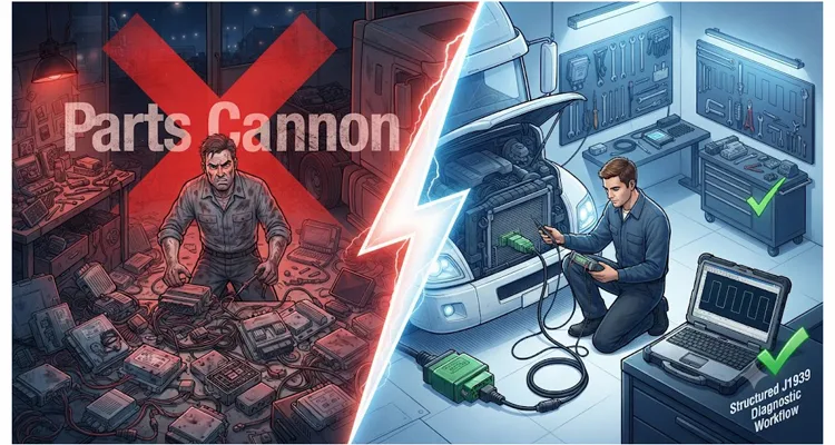
It’s two in the morning, and a refrigerated fleet just lost another truck. Every warning indicator across the gauge cluster fired at once — ABS fault, transmission derate, engine comms loss — painting a picture of multiple simultaneous failures that couldn’t possibly be real. The technician pulled the codes — J1939 timeout errors on half the modules — and went straight for the parts cannon. Over the next two weeks, he replaced the instrument cluster, the ABS ECU, the transmission ECU, a section of the cab harness, and even the engine ECM on a hunch. The bill for parts alone crossed forty-seven thousand dollars. Lost revenue from that one truck sitting idle was tracking around one thousand six hundred dollars a day. The root cause? A single corroded pin inside a weatherpack connector that was pulling the CAN Hi line low under vibration. Total repair cost, including a new pin and two cable ties: less than forty dollars.
The term “parts cannon” gets thrown around a lot, but we’ve quantified what it actually costs: in this case, component swapping outran troubleshooting by a factor of over a thousand to one in repair spend. That’s the kind of number that shows why shops need a structured diagnostic workflow for J1939 networks. When that workflow gets adopted, we’ve seen it cut fleet downtime by fifty percent or more — not because we sell diagnostic services, but because we’ve spent two decades engineering the cables, connectors, and harnesses that make those networks tick. After building a few hundred thousand J1939 cables for OEMs and diagnostic tool makers, you learn where the real faults live.
Why the Parts Cannon Is So Tempting on J1939
J1939 doesn’t fail gently. A single physical layer fault can bring down the entire powertrain bus, setting fault codes in five, ten, or fifteen modules simultaneously. A technician plugs in a laptop, sees a screen full of “timeout” and “invalid data” messages, and logic short-circuits: “If the ABS module can’t talk to the transmission, one of them must be dead.” Almost always, both are fine.
The underlying reason comes down to how SAE J1939 uses CAN 2.0B at 250 kbps. A clean differential signal across CAN Hi and CAN Lo keeps the bus alive, with two 120-ohm terminating resistors placed at the extreme ends of the backbone. But most training stops at “measure 60 ohms between CAN Hi and CAN Lo.” That’s table stakes. We’ve intentionally floated the shield drain on our test bench and watched the differential receiver’s input voltage drift outside its common-mode range even while resistance and DC voltages looked perfect. When that happens, modules don’t just lose frames — their CAN controllers enter bus-off state and trigger a cascade of timeout faults that look like multiple ECU failures. That’s the exact failure mode where a common-mode voltage shift silently kills J1939 communication, and no static ohm check will ever reveal it. That’s what turns guesswork into precision.
The Real-World Costs We’ve Tracked
We work directly with fleets, diagnostic tool builders, and heavy-equipment OEMs, and over the years we’ve accumulated real downtime data — not survey averages, but logs from shops that changed their approach.
A municipal bus fleet in the upper Midwest kept three rigs sidelined during a winter cold snap for what turned out to be water ingress in a J1939 backbone T-connector. Before adopting a physical-layer-first workflow, the average diagnostic-to-repair cycle for a bus-off event was fourteen hours. After training their crew to follow a no-guesswork sequence, that number dropped to just under four hours. Across their fleet of 120 buses, the annual reduction in shop hours and lost service days exceeded one hundred ten thousand dollars in savings.
Another case: an ag equipment OEM came to us after their field service teams were swapping entire engine-harness assemblies on combine harvesters to clear intermittent J1939 errors. An analysis of twenty returned harnesses revealed that seventeen had no electrical defect whatsoever — the real issue was a missing shield drain termination at the diagnostic connector, which allowed alternator ripple to couple onto the bus and create a phantom derate. The fix was a single ground strap and an improved diagnostic cable with a properly bonded shield, something we later designed into their OEM service kit. That change cut their per-incident warranty cost by roughly two thousand three hundred dollars, all without replacing a module.
A Structured Diagnostic Workflow: Physical Layer First, Logic Second
The workflow that consistently cuts downtime isn’t complicated, but it is rigid in sequence. Every step exists because skipping it has caused someone to chase ghosts for a full shift. I’ll write this from the point of view of a technician working on a truck or heavy machine with a suspected J1939 bus fault.
J1939 Step 1 – Interview the Operator, Not Just the DTCs
Fault codes tell you what the modules saw; they don’t tell you when, under what conditions, or what the machine was doing. Before a multimeter is even plugged in, ask:
- Did the event happen during cranking, heavy vibration, or after hitting a pothole?
- Was there a specific weather condition — rain, high humidity, rapid temperature change?
- Did any aftermarket equipment get installed recently? (Telematics trackers, body builders tapping the bus, LED light bars with noisy power supplies.)
One fleet we worked with traced a recurring “ABS timeout” to a specific bridge expansion joint on a highway. The vibration was flexing a hidden splice — exactly the kind of intermittent open that a proper wiggle test protocol is designed to catch. Without the operator’s note, they might have swapped three more ABS modules.
J1939 Step 2 – Map the Topology Before Probing
You can’t diagnose what you can’t draw. Sketch the J1939 backbone: where are the two terminating resistors? Which nodes branch off, and what is the stub length? Stub lengths that violate the one-meter rule cause signal reflections that can corrupt entire frames. The SAE J1939/11 specification calls for a maximum stub length of one meter for 250 kbps, but we regularly see factory installations with stubs pushing two meters due to routing constraints. Those need to be checked first.
While mapping, physically inspect each connector shell. Look for green corrosion, spread terminals, backing out of the weather seal, and incorrect locking. We manufacture connectors by the hundred thousand, and the number one field failure we see is a terminal that was never fully seated from the start — it makes contact until thermal cycling works it loose.
J1939 Step 3 – Resistance Checks with the System Asleep
Key off. Let the modules power down completely; on some trucks, this can take over three minutes. Disconnect any diagnostic interface. Measure directly at the 9-pin Deutsch diagnostic connector (pins C and D for J1939). This is the foundation of J1939 physical layer multimeter diagnostics. A J1939 9-pin pigtail breakout cable brings each circuit out to labeled test points, eliminating the need for back-probing and the intermittent contact that often produces misleading readings. Expected values:
| Measurement | Expected Value | If You See… | Likely Meaning |
| CAN Hi to CAN Lo | 60 Ω (two 120 Ω terminators in parallel) | 120 Ω | One terminator missing — we traced one to a backbone connector left unplugged after a cab tilt repair on a refuse truck. |
| CAN Hi to CAN Lo | 60 Ω | 40 Ω or less | Extra termination; a third resistor was accidentally wired in by a third-party telematics installer. No DTC for “extra resistor.” |
| CAN Hi to Ground | > 1 kΩ (ideally open) | < 100 Ω | CAN Hi shorted to chassis or shield drain somewhere — moisture in a sill connector pulled it down. |
| CAN Lo to Ground | > 1 kΩ | < 100 Ω | CAN Lo shorted to ground; we once found a pinched wire under a transmission mount bolt. |
| Shield to Ground | < 1 Ω | > 10 Ω | Poor shield bonding; noise immunity compromised. A combine harvester lost comms every time the alternator kicked in. |
Never trust a resistance reading taken while a module is even partially awake. A module’s internal CAN transceiver can bias the lines and make a 60-ohm network look like 47 ohms, sending you off on a wild goose chase.
J1939 Step 4 – Voltage Checks Under Load
With the key on and all modules awake, a healthy J1939 bus will sit at approximately 2.5 V recessive on both CAN Hi and CAN Lo relative to ground. CAN Hi will swing to about 3.5 V during dominant bits, CAN Lo to about 1.5 V. A multimeter set to average voltage will typically read around 2.6 V on Hi and 2.4 V on Lo if bus traffic is moderate.
If you see CAN Hi pegged at battery voltage or 0 V, there’s a short to power or ground, respectively. If both CAN Hi and CAN Lo read exactly the same voltage — say 2.5 V — but communication is dead, you may have a CAN transceiver that has failed but still appears to communicate, or the bus is stuck in a dominant state and one of the nodes is holding it there. This is where you move from multimeter to oscilloscope.
J1939 Step 5 – Capture a Waveform (One Good Frame, One Bad Frame)
An oscilloscope is the only tool that reveals signal integrity. Set up two channels, one on CAN Hi, one on CAN Lo, ground references at the diagnostic connector shield pin. Trigger on a single frame. A healthy waveform will show sharp, square transitions with minimal ringing and a clear differential eye pattern — what we look for in J1939 oscilloscope waveform diagnostics.
Signatures that scream “fix me”:
- “Shark Fin” – rounded shoulders on transitions: Excessive bus capacitance. Our test bench produces this when total bus capacitance crosses 100 pF, often from a stub pushed 2.3 meters on a combine.
- “Hedgehog” – reflection spikes after edges: Un-terminated or incorrectly terminated bus ends. We once traced one to a bulkhead connector where the terminating resistor was plugged in but the female pin had relaxed and wasn’t making contact.
- Collapsing differential voltage during a frame: A transceiver that can’t drive the full bus load, typically from water inside a connector creating a high-resistance short.
- Noise bursts synchronized with injector pulses or alternator ripple: Shield drain open, or twisted pair un-twisted for too long a run near a noise source — the same alternator ripple that induces phantom derates we saw in the combine case.
We have an engineering bench loaded with different configurations of our own J1939 cables specifically to replicate these exact failure signatures. When a customer describes a waveform over the phone, our engineers often can pinpoint the class of fault within minutes because we’ve induced every one of them in our test lab.
J1939 Step 6 – Isolate Methodically, Not Haphazardly
Once a physical layer fault is confirmed, the worst thing you can do is unplug modules at random. A J1939 network with a missing node can temporarily restore communication because the failing transceiver is no longer loading the bus — but you won’t know if the problem was the module or the stub leading to it.
Instead, break the backbone at a known access point: a bulkhead connector, a T-splitter, or the backbone junction near the engine ECM. Split the network in two, check resistance and signal quality on each half independently, and only then move toward the fault branch. This split-half fault isolation approach typically finds the fault in three splits instead of fifteen module swaps. When combined with a structured physical-layer toolkit, fleets have cut diagnostic time by seventy percent.
The Diagnostic Cable: The Component That Silently Corrupts CAN Frames
Technicians spend hours analyzing the vehicle wiring but rarely question the cable that connects their laptop or diagnostic tool to the 9-pin connector. A poorly built diagnostic cable can distort bus voltages and even inject noise. We’ve measured “budget” cables where the shield was floating, the CAN Hi and Lo wires weren’t twisted, and the insulation resistance dropped to single-digit megohms once humidity climbed above 60%.
This is where factory pedigree matters. Our facility produces J1939 diagnostic cables under the same roof as OEM harnesses for truck manufacturers. Every cable goes through four-stage inspection: automated continuity and short-circuit test, HiPot dielectric test at 500 VDC, CAN signal eye-diagram verification on a reference network, and finally a physical pull-and-lock test on every connector pin. The warehouse operates under 5S management with climate control to prevent material degradation before assembly.
Our full-plastic overmolded connectors meet RoHS and REACH standards, and we hold ISO 9001, ISO 14001, and IATF 16949 certifications — not as marketing badges, but because Tier-1 vehicle OEMs require them on every production line. The same RoHS-compliant, UL-listed wire stock and CE-approved connector shells that go into a production truck also go into the service diagnostic cables we manufacture. This is the same factory direct engineering capability we bring to every custom project.
When a diagnostic tool company approaches us, they don’t get a catalog and a price list. They get engineering support: impedance matching verification for their specific PCB layout, custom pinout mapping, laser marking with their logo, color-matched overmolds in any Pantone shade, cable lengths from half a meter to twenty meters, AWG selection from 18 to 24, and even custom packaging with their brand identity. That’s what twenty-plus years of direct factory experience translates to.
Recurring Diagnostic Traps That Keep the Parts Cannon Loaded
Even skilled technicians fall into these traps:
- Believing the first fault code. J1939 fault codes are symptoms, not diagnoses. An SPN 639 FMI 9 (J1939 Network #1, Abnormal Update Rate) almost never means the ECU that reported it is defective. More often, a backbone connector was unplugged with the key on during a PM, and the bus never re-initialized cleanly — a classic network calibration fault with a phantom cost.
- Measuring resistance with the key on. As mentioned earlier, waking modules corrupt the reading. A partially-awake CAN transceiver can bias the lines and pull a 60-ohm network down to 47 ohms, mimicking a third terminator. We’ve seen techs chase that phantom resistor across an entire combine chassis. Always measure dark.
- Using a test light on CAN lines. A standard incandescent test light can draw half an amp. On a CAN transceiver designed for milliamps, that’s a death sentence for one or more nodes. Use a high-impedance DMM only.
- Ignoring the shield drain on both ends. Many OEMs ground the shield at only one point to avoid ground loops. If a technician adds a second ground “for good measure,” they create a giant antenna and introduce a ground offset that leads to ECU misdiagnosis. Understand the vehicle’s shield topology before modifying it.
- Replacing modules based on a single captured frame without looking at the bigger picture. One error frame out of ten thousand is noise; one hundred error frames per second is a bus failing. You need a scope with enough bandwidth to catch the glitch that repeats under load.
Confirming the Fix Is Real
Repair isn’t complete until you prove that the bus stays clean under load and over time.
- Re-measure CAN Hi–Lo resistance and voltage; compare to baseline.
- Run the engine at varying RPM, operate all high-current loads (fans, wipers, HVAC blowers on max), and monitor the bus for error frames using a J1939 analyzer or oscilloscope in persistence mode for at least ten minutes.
- If the original fault was vibration-triggered, reproduce it physically: tap the harness with a rubber mallet while watching the waveform. We call it the “fist test,” and it’s the field equivalent of a documented wiggle test for J1939 harness opens. If the waveform even twitches, the fault is still there, hiding.
- Clear all fault codes, perform a key cycle, and confirm they don’t return after a road test that replicates the original complaint conditions.
A cheap diagnostic cable with a floating shield can fool you here: it may dampen noise during static testing but fail on the road. This is why high-end mobile service vans are increasingly switching to factory-grade diagnostic cables that match the vehicle’s original harness quality.
FAQ: What Engineers and Fleet Managers Ask Us About J1939
1. Can I use a generic OBD-II cable for J1939 diagnostics?
Not reliably. In our lab, we tested an off-the-shelf OBD-II cable with a J1939 adapter and measured a ten percent packet loss rate on a quiet bus. J1939 uses a 9-pin Deutsch connector, not the 16-pin OBD-II. The cable’s impedance mismatch and unshielded CAN lines introduced enough reflections to cause bit sampling errors and bus-off events. A properly terminated Deutsch 9-pin cable delivered zero frame errors under the same conditions.
2. What’s the difference between J1939 and CANopen?
Both are based on CAN, but J1939 uses a defined 250 kbps speed, 29-bit extended identifiers, and a strict set of Parameter Group Numbers (PGNs). CANopen is typically used in industrial automation with different framing and network management. They do not interoperate without a gateway.
3. How long can a J1939 backbone be?
Per SAE J1939/11, a maximum of 40 meters for 250 kbps. Stubs must not exceed 1 meter. In practice, many installations stay under 30 meters to maintain margin. Exceeding these limits drives up bit sampling errors, as we detailed in our guide on J1939 stub length and reflection timing.
4. Why do I have 60 ohms, correct voltages, and still no communication?
Bus overloading. Too many error frames or a node transmitting at an incorrect baud rate can saturate the bus even though the static measurements look clean. Use a scope or bus analyzer to check bus load percentage; it should stay below fifty percent under normal conditions. This is exactly the scenario where J1939 data link errors can be diagnosed in 20 minutes with the right approach.
5. Should the shield be connected at both ends or just one?
Most automotive and heavy-duty J1939 implementations connect the shield to chassis ground only at the source (typically near the ECM) to prevent ground loop currents. Always follow the vehicle manufacturer’s documentation.
6. How do I tell if a terminating resistor is internal to an ECU?
On many modern ECUs, the terminating resistor is software-configurable or internally hardwired and can only be verified by measuring resistance with the ECU disconnected from the backbone. If a module shows 120 ohms across its CAN Hi–Lo pins with the connector unplugged, it contains an internal terminator.
7. What’s a common sign of water in a J1939 connector?
Intermittent faults that appear after a wash bay cycle or rain. Resistance measurements may look normal when the connector is dry but drop dramatically when humidity is high. We’ve reproduced this in our lab by misting connectors with water — resistance between CAN Hi and ground can swing from megohms to under 100 ohms within minutes.
8. Can I splice J1939 wires just like regular automotive wiring?
Splices are allowed but must maintain the twisted pair geometry, and the untwisted region must be under 50 mm. Solder splices are not recommended in high-vibration environments; open-barrel crimps with adhesive-lined heat shrink are more durable. We manufacture repair pigtails that are one hundred percent tested for impedance consistency, precisely for this situation.
9. How does a structured approach actually cut downtime in half?
Because it eliminates the time spent replacing functional components, waiting for parts that aren’t needed, and chasing intermittent faults that get worse with every incorrect “fix.” In documented fleet cases, average time-per-repair drops from double-digit hours to under four hours, and the repeat-repair rate falls to nearly zero. Fleets that adopted a physical-layer-first ROI toolkit cut downtime by up to seventy percent.
10. Why is your factory’s diagnostic cable built differently from generic ones?
Because it’s manufactured on the same lines as OEM vehicle harnesses, under IATF 16949 quality systems, with full traceability from raw copper to finished assembly. We use RoHS-compliant materials throughout, full-plastic overmold designs that pass IP67 testing, and every single cable is 100% tested for CAN signal integrity — not batch tested. It’s the same standard that heavy-duty vehicle makers demand for production, applied to service tools. That’s why leading diagnostic brands choose our custom cable assembly factory for their own branded tools.
The Difference Between Replacing and Solving
A parts cannon approach doesn’t just waste money; it erodes confidence. When a truck comes back from “repair” and fails again the next day, the driver loses trust, the fleet manager starts questioning the shop, and the manufacturer sees warranty claims pile up for perfectly good components. A structured J1939 workflow stops that cycle cold. It forces the technician to prove the physical layer is healthy before pointing a finger at electronic modules — and in heavy-duty applications, the physical layer is guilty nine times out of ten.
It’s the same philosophy we apply when an OEM asks us to design a new J1939 harness or a custom diagnostic cable. We don’t guess at the specs; we measure, model, validate, and document — the same rigor you’ll find in our J1939 scope bench measurements for edge rates and differential voltage. That’s the precision part.
If your operation — whether a fleet, a diagnostic tool company, or an equipment manufacturer — needs engineering support to get J1939 connectivity right, reach out to us directly. We can build custom cables and harnesses to your brand, length, color, AWG, and pinout, with no minimum order that forces you into stock you don’t need. Our team provides OEM-level customization with logo, branding, and packaging as required, backed by a factory that holds UL, CE, REACH, and RoHS certifications, as well as IATF 16949 and ISO 14001 accreditations, and over twenty years of direct manufacturing experience.
Need help with a persistent J1939 problem, or looking to develop a reliable diagnostic cable under your own brand? Connect with us via WhatsApp at +8617307168662 or through our Contact Page. No immediate purchase conversations — just honest engineering discussion and precise custom solutions.
