

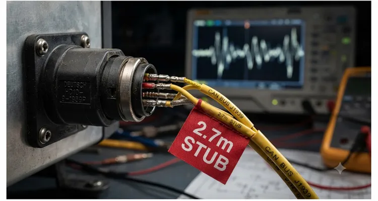
The transmission ECU dropped offline for exactly 417 milliseconds — I still keep the Vector log file ohio_truck3_ghost_node_004.asc as a reminder. Six identical refuse trucks. Same J1939 backbone layout they’d been running since 2015. Yet these six would randomly shed nodes. Sometimes the transmission ECU vanished for 417 milliseconds. Sometimes the body controller threw a timeout, then recovered. No pattern, no deterministic trigger, no DTC that made sense. The shop tech had already swapped the engine ECU, the transmission ECU, the terminating resistors, and even the main trunk cable. When I walked in, the first thing I asked was, “What’s the longest stub length in this build?”
He pointed to a neatly bundled harness branch feeding the roof-mounted telematics unit — 2.7 meters of twisted pair, spliced into the backbone behind the cab with zero thought given to reflection timing. That single stub was strangling the entire bus.
This article unpacks exactly how an overlong stub can tear down a J1939 network, walks you through calculating the reflection window with nothing more than a propagation delay figure and a bit timing diagram, and shows you how to fix it without re-engineering the whole harness. If you design, integrate, or troubleshoot heavy-duty CAN systems, the gap between a reliable backbone and a rolling headache is often less than a meter of wire nobody measured. I’ve written separately about the broader design decisions behind J1939 backbone termination and stub length rules — this article focuses specifically on the reflection timing physics and the calculation steps that let you quantify the problem before you cut a single wire.
The physics few people talk about at the harness bench
I used to think of a stub as just a tap. That changed after I injected a 50 ns pulse into a mock backbone on the bench and watched the reflection on a Tektronix TDS 3054. A 0.8-meter branch didn’t just delay the edge — it split it. The differential voltage collapsed to 0.9 volts for 80 nanoseconds, right where the TJA1050 datasheet says the receiver goes deaf. An impedance discontinuity isn’t a theory; it’s a voltage dip you can capture and timestamp.
At the physical layer, J1939 rides on CAN, and CAN depends on a linear bus topology with proper termination at each end — 120 ohms, exactly two resistors, no exceptions. I’ve been called to troubleshoot machines where a third terminator was added “for extra reliability” — the resulting DC bias shift made recessive bits look like noise. The moment you introduce a stub — a branch off the trunk to a node — you create that impedance bump. A voltage edge launched from any transmitter hits the junction, splits, and part of the energy fires back down the line. The longer the stub, the later that reflection arrives, and the more likely it hammers the receiver’s sampling point.
Stop fixating on the stub length in meters. The number that governs whether your bus survives is the round-trip flight time of the signal down the stub and back, measured against the bit time of your data rate. J1939 uses a nominal bit rate of 250 kbit/s, giving a bit time of 4 microseconds. A typical CAN controller samples the bus state at roughly 75% of the bit time — around 3 µs after the edge. If a reflection bounces back inside that window and drags the differential voltage below the dominant threshold, the sampler reads garbage.
Every meter of stub cable buys you about 10 nanoseconds of round-trip trouble. Propagation delay in standard SAE J1939/11 twisted pair sits near 5 ns/m, so the round-trip is 2 × L × 5 ns/m = 10 × L ns. For the sampler at 3 µs to stay clean, you need the reflection energy mostly dissipated by then. A field-proven rule of thumb I’ve settled on: keep the round-trip delay under 30% of the bit time so the first reflection decays enough that it can’t pull the differential voltage more than 150 mV. That caps the round trip at 0.3 × 4000 ns = 1200 ns. Do the division: L_max = 1200 ns / 10 ns/m = 120 m.
That 120-meter figure has driven more designs into a ditch than I can count, because it only holds if the stub is terminated into a perfect 120 Ω. It never is. In production vehicles, the node almost never terminates the stub. The transceiver’s recessive state presents high impedance — basically a small capacitance to ground — so the stub behaves as an unterminated transmission line, and the reflection coefficient at the node sits close to 1. The energy comes screaming back nearly in phase.
That’s why empirical limits for 250 kbit/s J1939 are far tighter. SAE J1939/11 calls for a maximum single stub length of 1 meter, with the accumulated stub length across all nodes not exceeding roughly 4 meters for unshielded twisted pair. I’ve watched systems fall over at 1.2 meters when the node capacitance exceeded 40 pF. I’ve also traced bit errors on a 0.5-meter stub back to an extra 0.3-meter service loop coiled at the connector — the coil and the node capacitance formed a parasitic LC resonance that sang at 16 MHz.
The Ohio diagnosis: a 2.7-meter rooftop stub
Back to the refuse trucks. The telematics unit lived on the cab roof, and the harness designer picked a dedicated branch from a backbone T-splice behind the dash straight up the A-pillar. The stub measured 2.7 meters from splice to connector. Round-trip delay: 2.7 m × 10 ns/m = 27 ns — an order of magnitude inside our 1200 ns budget. So why did it fail?
Because I wasn’t measuring to the transceiver die. The node’s internal PCB trace added another 80 mm of uncontrolled impedance, plus the connector’s parasitic capacitance, plus the telematics unit’s CAN transceiver with a recessive input capacitance of 35 pF hanging in parallel with a 22 kΩ pull-up to Vcc/2. That combination formed a low-pass filter at the stub tip, rounding the edge and slapping an extra 18 ns onto the effective reflection. Total round-trip sat around 45 ns — still within budget — but the reflected amplitude yanked the differential bus voltage down to 1.1 V on a recessive bit, violating the 1.5 V minimum threshold for the older NXP transceivers on the bus. The reflection didn’t need to hit the sampler dead-center; it just had to corrupt the recessive level during the arbitration field, and the node misread a dominant bit.
We proved it by unplugging the telematics unit at the roof connector, leaving the stub open. The differential waveform turned into an 8 MHz ringing mess that persisted for 180 ns after every transition. That open stub became a quarter-wave resonator at roughly f = v / (4L) = 200e6 m/s / (4 × 2.7) ≈ 18.5 MHz — close enough to the transceiver’s noise bandwidth to couple straight into the receiver threshold. The bus never stood a chance.
What you actually measure with a scope
Before you crunch numbers, capture the differential waveform with a high-voltage differential probe across CAN_H and CAN_L, right at the node logging errors. Trigger on a specific CAN ID you know generates failures, or run a pass/fail mask test if your scope supports it.
The fingerprint of a stub-induced reflection is a stair-step or hump on the differential signal immediately after the transition edge — typically 20 to 100 ns after the initial falling edge, scaling with stub length. It looks like a ghost edge that has no business being there. On a 250 kbit/s bus, a clean dominant-to-recessive edge settles within 100–150 ns. A problematic stub stretches that settling time past 300 ns, and you’ll sometimes catch the differential voltage dipping below +0.5 V when it should sit well above +2.0 V during a recessive bit. If you’re using a 50 MHz scope to chase these glitches, you’re likely missing half the story — a 100 MHz bandwidth reveals the true edge rate.
Take five captures at different nodes. If the reflection delay tracks the stub length — meaning the delay grows proportionally when you measure at a node farther from the stub — you have your smoking gun.
Fixing it without redesigning the vehicle
The cleanest fix is to re-route the backbone so the “stub” becomes part of the main trunk, putting the node in-line rather than on a branch. On the Ohio trucks, we pulled a new trunk segment up the A-pillar, relocated one backbone termination resistor to the roof telematics unit, and adjusted the opposite terminator to match. The total trunk length grew by 2.7 meters, but the stub length for that node dropped to zero. The J1939 network was rock-solid by the end of the afternoon.
When re-routing isn’t feasible — say, the node is potted into a hydraulic manifold — you have three other levers:
Stub reduction — and the hidden trap of connector re-pinning
Shortening the stub sounds trivial. The gotcha is that cutting a stub often forces you to re-pin a Deutsch connector in a spot with zero wire slack. I’ve built short adapter harnesses just to effectively move the splice point. Afterwards, physically measure the new length; never trust the harness drawing. A 0.6 m stub with a 12 pF node is a completely different creature than 0.6 m with a 45 pF node. Even reducing from 1.5 m to 0.6 m pushes the reflection energy well outside the bit sampling window.
Series resistance at the stub tap — carbon comp, not wirewound
Use carbon composition resistors. Wirewound parts are tiny inductors at the frequencies we care about, and they’ll turn your stub into a resonator. I learned this the expensive way with a batch of 39 Ω wirewounds that generated a 22 MHz ring exactly at the sampling point. Place a 20–50 Ω carbon comp resistor in series with each stub’s CAN_H and CAN_L lines, right at the backbone junction. This dampens the reflection but introduces a DC voltage drop; verify that the differential amplitude at the node still clears 1.5 V under worst-case loading.
Split termination at the problematic node — capacitor placement is everything
The 4.7 nF cap must sit within 5 mm of the node’s CAN pins. Any farther, and trace inductance kills its effectiveness. Install a split termination — two 60 Ω resistors in series, with the midpoint bypassed to ground through a 4.7 nF capacitor. This partially terminates the stub and burns off reflected energy right at the node. Only apply this when the node is at the end of a stub and you’ve confirmed it won’t disturb the overall bus termination scheme. This exact technique rescued a fleet of underground mining trucks where re-cabling was impossible because the node was sealed inside a hydraulic valve block.
The five common mistakes I see again and again
Trusting the 1-meter rule like it’s a law of physics
It’s not a law; it’s a guess until you measure the node capacitance. A 1-meter stub with a 40 pF node behaves nothing like a 1-meter stub with a 15 pF node. The capacitive load at the tip delays and shapes the reflection. Always measure the actual node capacitance (or pull it from the transceiver datasheet) and calculate the RC corner against the stub’s characteristic impedance. This is exactly the kind of phantom fault that costs fleets real money.
Building a star topology and calling it a backbone
Four nodes crimped together at a single physical junction with equal-length stub branches might look tidy, but you’ve built a multi-stub reflection festival. Every arm launches its own echo. This topology demands a hub with active CAN repeaters — not passive wire junctions.
That neat 12-inch service loop is a tank circuit
A coiled service loop behind the panel looks innocent. But a coil of twisted pair is an inductor, and when it resonates with the node’s capacitance, you’ve built a tank circuit that sings at frequencies J1939 transceivers are perfectly happy to amplify. Uncoil it or cut it out.
Mixing cable types because “it’s all twisted pair”
Dropping a section of 100 Ω ribbon cable into a stub, or using an unshielded twisted pair with a different twist pitch than the trunk, changes the local characteristic impedance. You’ve created a secondary reflection point inside the stub itself. The trunk and every stub must use the same 120 Ω nominal cable.
Assuming your 120 Ω resistor is actually 120 Ω
I’ve measured “120 Ω” cable from 112 to 128 Ω at operating temperature. When your termination is off by 10%, the reflection coefficient at the trunk ends jumps to 0.05 — and now the stubs aren’t your only reflection source. Termination resistance drift over temperature is real, and I’ve seen it turn a stable bench setup into a field failure. Match your terminating resistors to the cable’s actual measured characteristic impedance, not the catalog number.
Confirming the fix is real
After the harness modification, run three validation steps:
Eye diagram measurement
Trigger on any CAN ID and let persistence build for 60 seconds. The resulting eye diagram must show an opening at the node of at least 1.6 V high and 70% of the bit width wide. Any crossings inside the mask mean you still have signal integrity problems.
Bus loading stress test
Force every node onto the bus at its highest periodic transmit rate. Measure the differential voltage at the physical midpoint of the backbone with all nodes talking. It must stay above 1.5 V recessive and below 0.9 V dominant.
Stub tap waveform check
Probe right at the former stub-tap splice on the backbone. The dominant-to-recessive transition should settle without a secondary dip exceeding 150 mV.
On the Ohio trucks, after moving the backbone to the roof, the eye diagram cleaned up so dramatically that the fleet manager kept the scope trace on his phone to show visitors.
Hardware that eliminates the guesswork
When we build J1939 backbone cables and stub assemblies on our production floor, we never lean on rules of thumb. Every cable assembly runs through a vector network analyzer sweep that logs differential impedance, propagation delay, and attenuation at three frequency points before the connectors are even overmolded. That traceability matters when you’re supplying an OEM that absolutely cannot afford a field recall over intermittent CAN errors.
We’ve engineered custom backbone harnesses for refuse fleets, mining haul trucks, electric bus traction controllers, and marine propulsion systems — every one with stub lengths calculated and validated per node, never guessed. Whether your program needs a complete plug-and-play backbone kit with pre-terminated 120 Ω connectors or a short-run custom stub harness in a specific AWG and jacket compound, the engineering data package ships before the first article.
Our facility operates under IATF 16949 quality management, and we are also certified to ISO 14001 and additional international standards. Every harness goes through a four-step inspection that includes differential impedance verification. We stock SAE J1939/11 compliant cable in multiple AWG sizes, and we can brand, color-code, and laser-mark every assembly to your specification. The RoHS-compliant full-plastic connector housings are 100% tested before packaging. If your current J1939 backbone is giving you headaches a scope can’t quickly diagnose, the root cause is often a stub problem pretending to be an ECU failure. We can help you isolate it and build the harnesses that permanently fix it.
If you’re deep into a diagnostic puzzle and want to talk stub timing with someone who has been on both the factory floor and the roadside, reach out. We don’t work from a shopping cart — we discuss your topology, node count, cable routing constraints, and environmental requirements, then engineer the harness solution around those parameters.
Contact our engineering support team here and send over your backbone topology sketch. Or message us on WhatsApp and we’ll start the conversation before your next shift change. We do OEM custom cable assemblies, private labeling, and application-specific harness design — no catalog part numbers, just direct engineering collaboration.
FAQ
1. What’s the maximum stub length for J1939 at 250 kbit/s?
The SAE J1939/11 standard recommends a single unshielded stub no longer than 1 meter and a total accumulated stub length under 4 meters. In practice, depending on node input capacitances, even 0.6 meters can trigger signal integrity issues.
2. Can I use a single terminating resistor at one end of the backbone?
No. CAN physics demands exactly two 120 Ω termination resistors, one at each extreme end of the bus. Removing one changes the DC bias and leaves the line improperly terminated, dramatically amplifying stub reflections.
3. How do I measure the actual stub length causing a problem?
Disconnect the stub at the node, then use a time-domain reflectometer (TDR) or a scope with a fast pulse generator. The time to the first reflection peak gives the round-trip delay. Divide by 2 and multiply by the velocity factor of the cable to get physical length.
4. Does the CAN bit timing sample point affect stub sensitivity?
Yes. A controller sampling at 87.5% of the bit time has a wider margin than one sampling at 62.5%. If your network mixes ECUs from different suppliers, verify the sample point configuration in each node.
5. Can a stub problem appear only at certain temperatures?
Absolutely. Cable impedance and node input capacitance shift with temperature. A design that is marginally stable on a 25°C bench can tip into bit errors at -20°C or 85°C. Always validate the full operating temperature range.
6. Is there a difference between a “stub” and a “branch”?
In the J1939 world, the terms are interchangeable. Both describe a wiring segment that tees off the main trunk to connect a single ECU. The physics is identical: an unterminated transmission line stub that spawns a reflection.
7. What if I have an existing harness with multiple long stubs?
If re-routing isn’t possible, consider a CAN signal improvement device such as a stub eliminator or an active hub that isolates each node segment. This isn’t a substitute for sound topology design, but it can rescue a troubled fleet long enough to schedule a proper harness revision.
8. Should I ground the shield of the J1939 cable at every stub node?
No. Ground the shield at exactly one point — typically at the backbone connector nearest the vehicle’s central ground reference — to avoid ground loops that inject noise into the differential pair. Floating the shield at stub nodes helps suppress common-mode noise.
9. Can I use a single longer cable as a trunk extension and treat the original trunk as a very long stub?
If you extend the backbone, you must move one terminator to the new end and preserve the linear topology. The original trunk segment does not become a stub; it remains part of the trunk, with all nodes in-line, not on stubs. This is fine as long as the total length stays within the maximum bus length for 250 kbit/s (roughly 40 meters for unshielded twisted pair).
10. Do J1939 connectors matter for stub reflections?
Yes. Low-quality connectors create impedance discontinuities at the mating interface. Use connectors with controlled differential impedance designed to J1939/11, and never untwist the pair for more than 10 mm inside the backshell. On our own assembly line, we hold the untwist to under 5 mm — every extra millimeter adds series inductance that distorts the CAN edge.
