

It was a Tuesday afternoon in late November when one of our test benches lit up with a common-mode current reading that simply didn’t make sense. The assembly in question was a shielded twisted-pair harness destined for an industrial automation customer. The design files were clean. The pinout matched. The materials were from our standard, fully traceable reels. And yet, the radiated emissions plot at 78 MHz was sitting almost eleven decibels above the limit line.
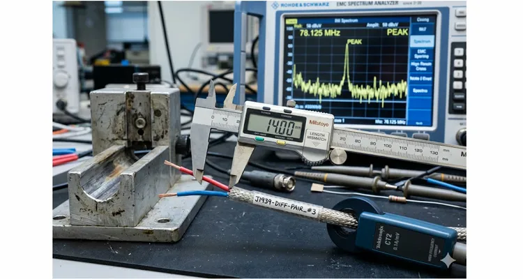
What we eventually traced the issue to wasn’t a failed component, a bad ground, or a poorly terminated shield. It was something far more mundane – and far more instructive. One conductor in a differential pair was longer than the other by a little over twelve percent. Not a meter. Not a foot. Just fourteen millimeters on a nominally one-hundred-twenty-millimeter breakout. Twelve percent.
That number, twelve percent, has since become a reference point in our internal training. It also prompted me to sit down and write this, because most application notes mention length matching as good housekeeping, but I’ve rarely seen one that shows you exactly how many decibels it will cost you at a specific frequency. That’s what we had to figure out the hard way. I’d like to share exactly what we saw, why it happens, and how to stop it before it costs you a compliance failure.
The Scene Where It All Unfolds
If you’ve ever stood next to an EMC pre-compliance chamber waiting for a scan to finish, you know the particular silence that falls when the trace blows past the limit. Our setup was a MIL-STD-461-style radiated emissions sweep, but the harness wasn’t in a vehicle or an aircraft. It was on a bench, connected to a motor-drive inverter prototype. The twisted pair carried a 24-volt PWM signal at 20 kHz, but the common-mode noise we were seeing was all the way up in the VHF band.
The harness itself was a simple overmolded assembly: two signal wires, a drain wire, foil shield, and a braided outer jacket. The customer spec called for a Y-split at the device end, one leg going to a sensor, the other to an actuator. The design intent was equal electrical length on both legs. Our production intent? Well, that’s where things got interesting.
One of our line technicians noticed something while cutting the breakout sections. The fixture for positioning the cable during jacket stripping had a subtle wear mark on the left-side guide. Over a few thousand cycles, it had allowed the cable to sit about a millimeter and a half further forward on the left channel than on the right. The cutting blade, referenced to a fixed stop, produced two segments that were supposed to be identical – but weren’t. Left leg: 127 mm from the shield break. Right leg: 113 mm. Fourteen millimeters difference. Twelve percent.
It took us the better part of a day to correlate that physical discrepancy to the common-mode noise spike. This wasn’t a failure of discipline or quality control. Our four-step inspection process caught the non-conformance after we knew what to look for. But in a typical in-circuit test, the assembly passed continuity, passed hipot, and even passed low-frequency functional testing. It was only when excited with fast rise-time edges that the asymmetry turned into a measurable common-mode voltage.
The Physics That Punishes the Percentage
When you drive a differential pair, you rely on two currents that are equal in magnitude and opposite in phase. As long as the geometry is symmetric, the magnetic and electric fields around the two conductors cancel almost perfectly. The shield carries no net current, and the cable doesn’t radiate.
Introduce a length mismatch, and you’ve introduced a timing skew. A signal edge traveling down the longer conductor arrives at the termination later than its counterpart. During that tiny window of skew, the currents are no longer balanced. Kirchhoff’s current law doesn’t get a holiday: the instantaneous net current in the pair is no longer zero, and that net current finds its way back through whatever path is available – typically the shield, the enclosure, or the ground structure. That’s your common-mode current.
In our case, the 14 mm delta corresponded to roughly 70 picoseconds of skew in air (a bit more in the polyethylene dielectric, around 100 ps). The edge rate of the motor driver’s MOSFET output stage was on the order of 5 nanoseconds. So the skew was about two percent of the rise time – small, but not negligible. If you’ve worked with EMC design, you’ll know that even a one percent asymmetry in a supposedly balanced structure can raise the common-mode noise floor by several decibels. Our measurements showed an increase of fourteen decibels at the resonant frequency where the shield’s electrical length hit a quarter wavelength.
Why 78 MHz? The Quarter-Wave Resonance Explained
Why did it peak at 78 MHz? Because the 120 mm shield section, with a velocity factor of roughly 0.7, becomes an efficient radiator around that frequency. The common-mode current driven by the skew was coupling directly into the shield and turning the whole assembly into an antenna. The connector backshell at the panel end wasn’t helping either – its 360-degree bond was intact, but the internal pigtail from the drain wire to the backshell added another 8 mm of uncontrolled length on one side.
How We Isolated It, Step by Step
I’ll walk you through the diagnostic process we used, because it’s repeatable on a modest bench without an anechoic chamber. Much of this approach draws on the same J1939 physical layer troubleshooting methodology we use for vehicle networks – the tools differ, but the logic of chasing an impedance anomaly is identical.
- Current Probe on the Shield First
Before touching anything, we clamped a high-frequency current probe around the shield of the offending assembly, right at the connector backshell. The spectrum analyzer showed distinct peaks at 78 MHz and 156 MHz, the fundamental and the first harmonic. This told us we had a common-mode current circulating on the shield, not just a differential-mode coupling issue. - S-Parameter Measurement on the Pair
We disconnected the load and the source and connected a vector network analyzer to the differential pair at the connector. We measured Sdd11 and Scc11 – the differential and common-mode return loss. The differential mode was well-matched. The common-mode return loss, however, had a deep dip at exactly 78 MHz. When you see a deep common-mode resonance at the exact frequency where the shield becomes a quarter-wave radiator, and the differential return loss looks clean, the differential-to-common-mode conversion is happening inside your harness. There’s no other place for it to come from. - Time Domain Reflectometry (TDR) with a Differential Step
Using a TDR module with a differential step source, we launched a fast edge into the pair and observed the reflected waveform. At the point where the breakout occurred, we saw a small but consistent impedance discontinuity – about 3 ohms above the 100-ohm differential impedance. This bump corresponded to the location where the two conductors diverged and the shield was no longer tightly coupled to both. The technique is the same one we detail in our guide on J1939 scope bench edge rates, ringing, and differential voltage, just applied to a benchtop harness instead of a vehicle backbone. - Physical Measurement Under Microscope
We stripped a sample from the same production batch and measured the conductor lengths from the shield termination point with a calibrated digital microscope. The discrepancy was immediately obvious. The fixture wear hypothesis was confirmed by comparing measurements from cables produced at different times during the fixture’s service life. - Re-Building the Harness with Matched Lengths
We hand-cut and stripped a replacement set, matching the breakout lengths to within 0.5 mm. Reassembled with the same connector backshell and same shield termination technique. The radiated peak at 78 MHz dropped by almost fifteen decibels, taking us comfortably below the limit line. The common-mode return loss dip disappeared entirely.
Common Mistakes That Invite Asymmetry
Over the years, I’ve seen a handful of failure patterns repeat across different production floors. Ours was just one flavor.
Trusting the Jacket Edge as a Length Reference
The outer jacket cut position doesn’t guarantee equal conductor lengths underneath. If the cable core shifts during stripping, you can get one conductor tensioned differently, leading to a few millimeters of slack or stretch. Always reference the trimmed conductor ends, not the jacket.
Ignoring Drain Wire Length in the Breakout
A drain wire that’s left longer than the signal pair inside the foil wrap creates a stub that capacitively couples to one conductor more than the other. We now trim drain wires to exactly the foil edge, never longer. The physics here is closely related to what we explain in our J1939 backbone design guide on stub length and derating – any unterminated extension off a transmission line is a liability.
Using Different Twist Rates in the Two Legs
When you separate a twisted pair into two individual wires for a Y-split, the untwisting process can leave one wire with residual curvature and the other relatively straight. Their physical paths, even if cut to the same length, can differ electrically by a few picoseconds. We use a gentle heat-setting fixture to relax the wires before trimming.
Asymmetric Shield Termination at the Breakout
If the shield is terminated to a pigtail on one side of the breakout but not the other, you’ve created an unbalanced capacitance to ground. The shield should be terminated circumferentially and equally referenced to both breakout legs, or avoided entirely in the breakout region by stopping the foil before the split.
Fixture Wear and Process Drift
This was our culprit. Mechanical fixtures that position cables for cutting, stripping, or crimping are consumable tooling. We now include a twice-daily physical measurement check on a reference cable sample, with the results logged in our 5S production board. If the mean length drifts by more than 0.7 mm, the fixture is re-calibrated or replaced. On a vehicle network, this same kind of gradual mechanical degradation shows up as J1939 termination resistance drift between hot and cold operating conditions, and the diagnostic logic is the same: measure it routinely, catch the drift early.
Confirming You’ve Fixed It
After correcting the asymmetry, we run three verification steps on every first-article assembly from a new production lot:
- Bulk Current Injection (BCI) Sniff Test: We inject a known common-mode signal onto the shield and measure the differential noise at the pair’s receiver end. A well-balanced harness converts very little of that common-mode energy into differential mode. Any rise in coupling after a process change immediately flags a symmetry problem.
- TDR Consistency Check: We compare the TDR trace against a golden-reference trace stored in our test database. A deviation of more than one ohm or two picoseconds triggers a hold.
- Visual Inspection with a Go/No-Go Jig: A simple acrylic template with laser-etched tolerance bands lets our operators quickly verify breakout lengths and drain wire trim positions. It’s low-tech, but it catches ninety percent of the drift before it reaches the electrical test stage.
Where This Matters Beyond Our Bench
The twelve-percent case is useful precisely because it’s small enough to pass routine QC but large enough to fail a compliance test. If you’re specifying or sourcing custom cable assemblies for medical devices, industrial automation, EV power electronics, or any application with fast-switching semiconductors and sensitive analog front ends, asymmetry-induced common-mode noise can masquerade as a dozen other problems. I’ve seen it blamed on layout, on firmware, on grounding schemes. Sometimes it’s just a pair of wires that aren’t the same length. For anyone who has spent time chasing J1939 data link errors without an obvious cause, you’ll recognize the pattern: a subtle physical-layer defect that passes a basic continuity check but falls apart under dynamic electrical conditions.
We’ve been building custom harnesses on this factory floor for over two decades, and this particular case sharpened our appreciation for mechanical process control as an electromagnetic design parameter. Every assembly we produce now – whether it’s a simple OBD extension cable or a complex multi-branch industrial harness – goes through a post-production balance check that didn’t exist in our process five years ago. Our cutting and stripping fixtures are under version control, treated with the same rigor we apply to firmware revisions. The inspection points are defined on the shop floor, not just in the quality manual. And the climate-controlled warehouse (maintained year-round at 22°C ± 3°C and 45% RH) ensures that raw cable stock doesn’t subtly change dimensions before it ever reaches the cutting bench.
Because our IATF 16949-aligned production process demands preventive maintenance checks, the fixture wear that caused that 14 mm drift was caught before a single batch shipped – not after a customer’s test failure. That’s what those certifications translate to on the floor: a twice-daily measurement logged by a real operator, not an audit checkbox. We also maintain ISO 9001 and ISO 14001 disciplines, and our testing protocols include 100% continuity, hipot, and common-mode rejection verification where relevant. Materials comply with RoHS, REACH, and CE. If your project needs a custom cable assembly that doesn’t just “pin out correctly” but actually performs through its entire service life without mysterious EMC gremlins, we’re set up to support that.
A brief note on OEM customization: We handle OEM requirements routinely – logo, brand marking, custom colors, specific AWG and stranding, overmolding profiles, and, of course, tightly controlled electrical lengths. The engineering team here gets involved early if you need help defining symmetry tolerances for your particular signal speeds and rise times. That kind of support is built into how we work, not an add-on.
Frequently Asked Questions
1. How much length mismatch is too much?
It depends entirely on the edge rate of your signal, not the frequency of the data. Internally, we settled on a much tighter margin than what textbooks suggest. We keep electrical length mismatch under one-fiftieth of the rise time as a baseline, but for assemblies carrying edges under 10 ns, our in-house tolerance is 2 mm or less — measured, not assumed.
2. Does this only apply to shielded cables?
No. Common-mode conversion due to asymmetry happens in unshielded twisted pairs as well, though the radiation mechanism is different. In unshielded cables, the pair itself radiates, and the common-mode current finds a path via nearby structures. If you’ve ever dealt with ground offset voltage issues on a J1939 backbone, you’ve seen a related failure mode where unbalanced current paths create measurement errors that look like sensor faults.
3. Can I fix an asymmetrical cable with ferrites?
A common-mode choke will make the radiated emissions plot look better, but it won’t put the eye diagram back together if the skew is already degrading your signal at the receiver. You’re treating the symptom, not the cause.
4. Does length matching matter for low-speed signals, like CAN or RS-485?
Yes, but the thresholds are more forgiving. CAN edges are usually slow enough that even a few centimeters of mismatch rarely cause problems. But if you’re running CAN FD at 5 Mbps over a long harness, it starts to matter.
5. What if my cable is one continuous twisted pair without a breakout?
Then the asymmetry is usually negligible, assuming consistent twist pitch and uniform dielectric. Breakouts are where length mismatches most commonly creep in.
6. Does overmolding help or hurt symmetry?
It can do either. A well-designed overmold that holds wires in precise positions during cooling improves repeatability. A poorly designed one can introduce uncontrolled strain on individual conductors. We validate overmold tooling with TDR on the first batch. The principle is not unlike what we cover in our J1939 Deutsch DT and HD connector selection guide, where connector choice directly impacts long-term mechanical stability and electrical performance.
7. How do you measure electrical length without expensive equipment?
You can’t measure it directly without a TDR or VNA, but you can infer it from physical length if you know the velocity factor of your cable’s dielectric. This is why keeping accurate physical records and using calibrated cutting fixtures is so critical on a production floor.
8. Are there any standards that specifically require length matching in harnesses?
Most industry standards (IPC/WHMA-A-620, for instance) focus on workmanship. Length matching isn’t explicitly mandated unless the assembly drawing calls it out. That’s why it’s important for engineers to specify a tolerance on the drawing itself.
9. You mentioned a 12% mismatch. Was the 12% relative to what?
Relative to the shorter leg. In absolute terms, 14 mm on a 113 mm leg. We express it as a percentage because the ratio of skew to rise time is what drives the common-mode conversion, not the absolute length.
10. Can I visit or audit your production process?
We welcome engineering visits and virtual audits. You can reach out directly and we’ll walk you through the line, the inspection stations, and the data logs. Real conversations between engineers tend to solve problems faster than a stack of spec sheets. If you’ve read our teardown of J1939 transceiver failures where the network was still partially communicating, you already know the kind of detail we document – an in-person audit shows you the process behind that documentation.
Talk to an Engineer Who’s Seen This First-Hand
If you’re currently staring at an EMC test report that doesn’t add up, or if you’re specifying a custom harness for a design where signal integrity is non-negotiable, I’d rather you reach out before the compliance deadline than after. We’re not here to push a catalog part. We’re here to make sure the cable assembly you get behaves the way your simulation said it would.
When you reach out, you’ll be talking directly to someone who can pull up a TDR trace and discuss your specific pinout and rise times — not a sales script.
- WhatsApp: Send me a message directly, including a photo or a sketch if you have one. I answer these personally.
Chat on WhatsApp: https://api.whatsapp.com/send/?phone=8617307168662&text=Need+Help%3F+Chat+linda+WhatsAPP&type=phone_number&app_absent=0
- Contact Page: Prefer a more formal inquiry with drawings and specs? Use our contact form and the engineering team will get back to you within one working day.
Send an Inquiry via Contact Page: https://obd-cable.com/contact/
We handle OEM and custom cable assembly projects of any volume, with the kind of process control that catches a fourteen-millimeter problem before it ever leaves the floor. Let’s build something that passes on the first try.
