

A 2019 Freightliner Cascadia refused to regenerate on a cold February morning in Salt Lake City. The driver cycled the ignition three times. The dash flashed a “Check DEF System” warning, then went dark after a restart. The shop pulled the J1939 fault codes: SPN 639, SPN 1231, SPN 4334. Three separate ECMs, all pointing to loss of communication. The first instinct was to replace the aftertreatment control module. That was a one-thousand-two-hundred-dollar part. It didn’t fix the problem.
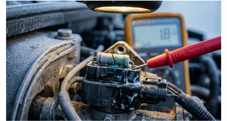
Two weeks later, the same truck came back on a hook. This time, the technician spent six hours tracing the CAN backbone with an oscilloscope. He found a single 120-ohm termination resistor inside the engine bay connector that had drifted to 1.8 kilo-ohms. The resistor itself cost twenty-three cents. The total downtime, parts thrown at it, and labor cost the fleet just over four thousand dollars. The driver lost hours, the load was late, and the real fault was a passive component that nobody thought to check first.
I’ve seen this exact story play out across mining trucks in Australia, municipal buses in Germany, and agricultural harvesters in Brazil. It’s never just a resistor. This isn’t a one-off. It’s baked into how most fleets train their techs and stock their parts rooms. If you’re a fleet manager or an engineering lead at a Tier-1 supplier, you can run the numbers yourself: a single CAN bus termination failure per hundred vehicles per year, with an average diagnostic bill of three thousand eight hundred to four thousand two hundred dollars, multiplied by your fleet size and failure rate. The root cause is almost never the silicon. It’s the physical layer.
The CAN Bus Physics Most People Ignore
A CAN bus is a differential transmission line. The ISO 11898-2 standard defines the characteristic impedance at one hundred twenty ohms, a value derived from the transmission line theory governing unshielded twisted pair cable. The two termination resistors at each end of the backbone are not optional accessories. They absorb signal reflections that would otherwise bounce between nodes and corrupt bit timing.
When a resistor drifts high — and I mean anything above one hundred thirty-two ohms — the bus no longer properly terminates. The signal overshoots, the recessive-to-dominant edge rings, and the transceiver’s differential threshold comparator starts seeing false edges. At low bus loads, the network might still work intermittently. The fault only manifests when the bus utilization crosses forty percent, or when temperature swings push the transceiver bias points. This is why the problem is seasonal. This is why “it only happens on cold starts.” This is why technicians replace modules that test perfectly on the bench.
The failure mode isn’t always open circuit. I’ve dissected failed resistors from field returns under a microscope. Common modes:
- Carbon film drift: Moisture ingress through a micro-crack in the resistor body causes the carbon film to oxidize. Resistance climbs slowly over eighteen to twenty-four months.
- Silver migration in thick-film terminations: In high-humidity environments with DC bias, silver ions migrate from the termination electrode toward the resistive element, creating a high-resistance shunt path.
- Solder joint fatigue on PCB-mount resistors: The resistor is fine. The solder joint developed a hairline crack from thermal cycling. Resistance measured at the resistor leads reads correct; resistance measured at the connector pin reads open.
All three modes produce exactly the same symptom: intermittent CAN communication loss that no generic OBD-II scan tool will definitively flag.
The Diagnostic Connector Is Part of the Circuit
Here’s something the datasheets don’t tell you. In many commercial vehicle applications, the termination resistor lives inside the diagnostic connector or a weather-pack inline connector, not on a pristine PCB. This means the resistor body is subjected to:
- Engine bay temperatures cycling from minus forty degrees Celsius to one hundred twenty-five degrees Celsius
- Diesel exhaust fluid mist — urea is corrosive to tin-plated terminations
- Pressure washing at two thousand PSI
- Vibration profiles that exceed twenty G on mining equipment
A generic through-hole carbon film resistor with basic tin-plated copper leads will fail under these conditions within eighteen months. I’ve confirmed this in accelerated life testing on our own diagnostic cable prototypes. Yet I still see cables shipped with exactly this bill of materials. Why? Because the resistor cost is twenty-three cents instead of forty-five cents for a metal film resistor, conformally coated, welded-lead version that would last the vehicle lifetime.
The twenty-two-cent savings on one component costs four thousand dollars downstream. The engineer who specified the cheap resistor never sees the fleet repair bill. That disconnect is the entire problem.
How to Diagnose CAN Bus Faults Before You Fire the Parts Cannon
You don’t need a Vector VN1670 to find a bad termination resistor, but you do need to know the topology. Before you touch any module, do this:
First, measure the bus resistance with everything dead.
Disconnect the battery. Go to the diagnostic connector — usually the 9-pin Deutsch connector on heavy-duty trucks, or the 16-pin OBD-II connector on light-duty. Measure between CAN High and CAN Low with a decent multimeter. A Fluke 87V or equivalent, not a ten-dollar throwaway. You should see approximately sixty ohms, because you’re measuring two one-hundred-twenty-ohm resistors in parallel. If you need a reliable breakout cable to access these pins without back-probing, our J1939 9-pin pigtail breakout cable gives you clean test points for CAN_H, CAN_L, and ground right at the connector face.
If you see one hundred twenty ohms, one terminator is gone.
Trace the CAN backbone. Find both terminating ends. One is typically in the engine ECU connector, the other near the cab bulkhead or aftertreatment module. Measure each one individually by disconnecting that node. This is the 120-ohm reading on pins 6 and 14 that most techs misdiagnose as a module failure because the scan tool still connects intermittently. If you’re dealing with a J1939 backbone where the termination resistance drifts with temperature, measure cold and hot before condemning any single component.
The eighty-five to one hundred ten ohm zone is where the real headaches live.
This is the dangerous range. The bus partially works. A scan tool will connect. You’ll get false confidence. Measure each termination node independently. Replace anything outside the one hundred fifteen to one hundred twenty-five ohm band. I’ve seen this exact resistance band cause phantom faults that cost fleets thousands in misdiagnosis before anyone thinks to check the resistor.
Check the common-mode choke if equipped.
Some OEMs place a common-mode choke in series with the CAN lines at the diagnostic connector. A shorted turn in the choke can present as a shifted termination impedance. Disconnect the choke and measure again. If you’re chasing a common-mode voltage shift on a J1939 network, the choke is one of three things I check before touching any ECU.
Wiggle test while measuring resistance.
This catches the hairline solder joint failures. Set your meter to continuity or resistance, and physically flex the connector body while watching the reading. Any fluctuation means the termination assembly is failing mechanically. We formalized this into a wiggle test protocol for J1939 harness opens after watching too many technicians replace modules for what was ultimately a cracked solder joint inside a Deutsch connector.
The entire diagnostic sequence takes twenty minutes. Twenty minutes versus replacing a four-thousand-dollar ECU stack.
What the Right CAN Termination Resistor Looks Like
If you’re building diagnostic cables or specifying harnesses for your fleet, the table below is what I’d put in a procurement spec for a fleet operating anywhere with real temperature swings or humidity — places where a roadside failure isn’t an inconvenience, it’s a safety issue or a missed delivery window that costs real revenue.
| Parameter | Minimum Acceptable | Why It Matters |
| Type | Metal film, thick-film chip with conformal coat | Carbon film drifts under humidity |
| Tolerance | ±1% (not ±5%) | CAN spec allows ±3% total bus impedance variation including connector contact resistance |
| Temperature Coefficient | ±50 ppm/°C max | Engine bay swings 165°C; a 200 ppm/°C resistor shifts 33 ohms |
| Power Rating | 0.5W minimum | Transient bus faults can dump energy into the termination; 0.25W parts fuse open |
| Lead attachment | Welded, not crimped | Crimp joints develop intermetallic growth under thermal cycling |
| Connector pin plating | Gold over nickel, minimum 30 microinches | Tin-plated pins fretting-corrode in high-vibration environments |
| Sealing | IP67 if in engine bay | Pressure washing and DEF mist ingress |
This resistor costs about forty-five cents in production quantities. Twenty-three cents more than the cheap one. Over a ten-thousand-unit production run, that’s a two-thousand-three-hundred-dollar increase in BOM cost. One avoided fleet downtime event covers the difference. When I walk fleet managers through the ROI of basic physical layer tools, the twenty-three-cent resistor upgrade is always the line item that makes them stop and stare at the spreadsheet.
The OEM Diagnostic Cable Trap Nobody Talks About
A number of OEM diagnostic cables on the market use PCB-mounted resistor networks inside overmolded connectors. The theory is fine: integrate termination resistors onto a small ceramic substrate, overmold with thermoplastic, and you get environmental protection “for free.”
The reality is different. The overmolding process subjects the ceramic substrate to injection pressures exceeding five hundred PSI at two hundred forty degrees Celsius. Micro-cracks develop in the resistor element that don’t show up during end-of-line continuity testing. They propagate over six to twelve months of thermal cycling. By the time the diagnostic cable fails in the field, the original production lot has already shipped globally.
We caught this failure mode during a root cause analysis for a European bus manufacturer in 2021. The fix was not a different resistor. The fix was moving the termination resistor outside the overmold into an accessible, serviceable inline connector. Now if a termination drifts, the technician replaces a seven-dollar pigtail assembly instead of the entire two-hundred-dollar diagnostic interface cable.
Designing for Serviceability in Diagnostic Cables
Engineers who’ve never turned wrenches design non-serviceable assemblies. Engineers who’ve spent time in a service bay design things differently. A good diagnostic cable should let a technician verify termination resistance without cutting open the overmold. A few principles that cost nothing to implement but save thousands downstream:
- Label the termination nodes. A simple “TERM: 120Ω” molded into the connector body tells the technician where to measure.
- Expose test points. Two small pinholes in the connector backshell, clearly marked CAN_H and CAN_L, let a multimeter probe make contact without back-probing pins.
- Use serviceable inline resistor carriers. A small weather-sealed holder that accepts a standard quarter-watt resistor. If it fails, swap the resistor, not the harness.
- Document the bus topology in the cable datasheet. Include a one-line diagram showing exactly where the termination resistors sit. If you’re maintaining a mixed fleet, a proper J1939 backbone termination and stub length guide in the cable documentation prevents double-termination mistakes that are shockingly common in the field.
These four things add maybe one dollar to the total BOM. They’re never in the RFQ because the procurement team doesn’t know to ask for them. Engineering has to lead here.
Factory Process: Why It Matters to the End Customer
You don’t need to care about the factory until you’ve received ten thousand cables that fail at a two percent rate in the field. Then you care deeply. Two percent of ten thousand is two hundred field failures. Each one triggers a technician visit, a warranty claim, and a very unhappy fleet customer.
I can give you the same schematic as a competitor. If their factory skips the four-wire Kelvin measurement on incoming resistors, their cables will fail at two percent and ours will fail at zero-point-zero-five. The drawing doesn’t dictate that outcome — the QA does. Here’s what that looks like on our production floor.
Every batch of termination resistors goes through incoming QA with a four-wire Kelvin resistance measurement on a statistically valid sample. The acceptance band is one hundred eighteen to one hundred twenty-two ohms at twenty-three degrees Celsius ambient. Parts outside this band get rejected before they ever touch a PCB.
After SMT placement or hand-soldering, depending on the connector design, every single cable goes through a four-step inspection: automated continuity and short-circuit test on all pins, CAN bus impedance measurement at the connector face verified against the design spec, high-pot test at five hundred volts DC between signal lines and shield where applicable, and a functional CAN communication test with a reference ECU running a ten-minute stress test at one-megabaud bus load. This is the same approach we use to catch J1939 transceiver failures that still communicate — a fault that passes basic continuity but fails under load.
The test data gets logged against the cable serial number and stored. If a customer reports a field failure three years later, we pull the QC records for that exact unit. That traceability is not a marketing point. It’s what lets us find and contain latent defects before they become a recall.
When we qualified for IATF 16949, the auditor spent three hours on one thing: our traceability system. Every reel of termination resistors gets a lot code that follows the part through placement, soldering, testing, and into the finished cable serial number. If a field failure comes back, we don’t guess. We pull the inspection record for that exact unit. The 5S methodology on the floor isn’t about looking tidy for visitors — it’s about making sure a reel of five-percent-tolerance resistors never accidentally gets loaded into a feeder meant for one-percent parts. That substitution happens more often than most factories admit. Our moisture-sensitive components sit in climate-controlled storage at twenty-three degrees Celsius and thirty-five percent relative humidity until they’re kitted. Our management system is certified to ISO 9001, IATF 16949, and ISO 14001, with products conforming to RoHS, REACH, CE, and UL standards. These things don’t guarantee zero defects, but they make defects rare and traceable.
Common Mistakes I’ve Seen in the Field
Mistake 1: Measuring CAN resistance with the battery connected.
The transceivers bias the bus. You’ll read incorrect values. Always disconnect battery power before measuring termination resistance.
Mistake 2: Replacing only one termination resistor when the other has also drifted.
If one resistor drifted due to environmental exposure, the one at the other end of the CAN backbone experienced the same conditions. Replace both. This is especially true on J1939 backbones where a 0.3V ground offset accelerates corrosion on both terminator nodes simultaneously.
Mistake 3: Using a cheap OBD dongle as a diagnostic tool for CAN physical layer faults.
Consumer-grade dongles connect at the protocol level. They don’t measure bus impedance. A physical layer fault looks like “intermittent no-communication” at the protocol level. You need a multimeter or oscilloscope. If your fleet is debating whether to invest in proper diagnostic tools, I’ve already done the math on the fleet oscilloscope cost-benefit decision — the tool pays for itself on the first avoided ECU swap.
Mistake 4: Ignoring the shield termination.
J1939 specifies a shield that should be terminated to ground at exactly one point to avoid ground loops. If your diagnostic cable has a shield termination resistor that’s failed open, the shield floats and becomes an antenna for EMI. Your CAN frames get corrupted by the alternator ripple. I covered the exact mechanism in detail when analyzing how common-mode voltage on J1939 kills communication on otherwise healthy-looking networks.
Mistake 5: Assuming new cables are good cables.
Test them before deployment. I’ve seen brand-new cables from low-cost suppliers ship with the wrong resistor value because the production line used a five-percent-tolerance part where a one-percent part was specified. The BOM substitution happened without engineering approval. A 20-minute physical layer test before installation saves an eight-hundred-dollar diagnostic fee later.
How to Verify a Fix on a CAN Bus System
After replacing a termination resistor or a diagnostic cable, don’t just clear the DTCs and send the truck. Do this:
- Measure CAN High-to-Low resistance at the diagnostic connector with power off. Verify sixty ohms ± three ohms.
- Measure CAN High-to-ground and CAN Low-to-ground. Both should read open circuit — or high impedance in the megohm range — with power off.
- Start the vehicle and run all major actuators: HVAC fan on high, electric cooling fans cycling, DEF dosing active, all exterior lights on. These load the electrical system and generate EMI. If the bus is marginal, this is when it will glitch. If you’ve ever dealt with PTO interference on a logging fleet, you know that accessory loads are the real test, not idle.
- Use a scan tool to check for “Lost Communication” DTCs that are “Pending” or “History.” Clear them, run a full drive cycle, and re-scan.
- If you have access to an oscilloscope, capture a CAN frame and verify the differential voltage swing is between 1.5V and 3.0V dominant, and within ±50mV recessive. Check for excessive ringing on the recessive-to-dominant edge. If you’re unsure what a healthy waveform looks like, I published a reference for J1939 waveform analysis using a 200-dollar USB scope that covers edge rates, ringing thresholds, and differential voltage limits.
If it passes all five checks, the physical layer is solid. The twenty-three-cent fault is closed.
Question: Why one hundred twenty ohms? Who picked that number?
Answer: It’s not arbitrary. It’s the characteristic impedance of the unshielded twisted pair cable used in vehicles. Transmission line theory, not a committee vote. Matching the termination to the cable impedance minimizes reflections.
Question: Can I just grab any 120-ohm resistor from the parts bin?
Answer: You physically can. The truck will probably start and run. But I recommend metal film with welded leads, conformal coating, and a documented temperature coefficient under fifty ppm per degree Celsius. Six months later, when the engine bay has cycled from minus twenty to plus ninety a few hundred times, a generic carbon film resistor will have drifted and you’ll be chasing ghosts again. This is the same physics behind why J1939 termination resistance drift depends on whether you measure hot or cold — the value you read on a workbench at twenty-three degrees Celsius is not what that resistor does at minus thirty.
Question: Can I use a cable with a switchable termination?
Answer: Some cables include a small slide switch on the connector body to enable or disable the built-in termination. This is useful if you need to add the cable to an already-terminated bus without double-terminating. If your cable has a fixed termination and you need to remove it, don’t cut it out with wire cutters — that’s not field-appropriate. Get a cable designed without termination from the start. I’ve seen double-termination mistakes create bit sampling errors that push a J1939 node into Bus Off without any obvious wiring fault.
Question: How do I know if my termination resistor is failing intermittently?
Answer: The classic symptom is communication faults that correlate with temperature or humidity. If the truck loses CAN communication on cold mornings but works fine after warming up, suspect the termination. Thermal expansion closes a hairline crack in a solder joint; cold opens it. I’ve seen this pattern enough times that it’s now the first place I look. The same thermal-mechanical failure shows up in J1939 sampling point diagnostics when the bit timing margin shrinks just enough to fail at cold-start but recover when the transceiver warms up.
Question: Is this problem specific to heavy-duty trucks?
Answer: No. Passenger vehicles use the same high-speed CAN spec, ISO 11898-2, with the same 120-ohm termination requirement. But passenger car connectors are generally better sealed against the environment, so the failure rate is lower. Commercial vehicles, agricultural equipment, and construction machinery see far more aggressive environmental exposure, which is why fleets in those sectors encounter this fault more often.
Question: What’s the difference between a terminating resistor and a biasing resistor?
Answer: Termination resistors are 120 ohms across CAN High and CAN Low and they prevent reflections. Biasing resistors are pull-up and pull-down networks, typically a few kilo-ohms each, that hold the bus in a known recessive state when no node is driving. Some transceivers integrate biasing; others require external resistors. They serve completely different purposes. Don’t mix them up.
Question: Can a bad ground connection mimic a termination resistor fault?
Answer: Absolutely. If the ECU ground shifts relative to the sensor ground, the CAN transceiver’s common-mode range gets violated. You’ll see intermittent bus errors that look just like a termination issue. Always verify solid chassis grounds before chasing termination problems. I’ve learned this the hard way on more than one occasion, and I’ve documented the diagnostic sequence for J1939 ground offset voltage diagnosis separately because it’s the single most misdiagnosed physical layer fault in commercial vehicle networks.
Question: Does bus length affect termination requirements?
Answer: Yes. CAN is specified for bus lengths up to forty meters at one megabit per second. At longer distances, you reduce the data rate. At very short bus lengths, under one meter, some systems can function with a single termination, but this is not compliant with ISO 11898-2 and should be avoided in production. Don’t build a non-compliant bus just because it happens to work on your bench. If you’re designing a J1939 backbone and wondering whether to derate from sixty ohms, the physics doesn’t care about your production schedule — it cares about impedance matching.
Question: Does CAN FD have different termination requirements?
Answer: CAN FD uses the same physical layer as classical CAN, so the 120-ohm termination requirement is identical. But CAN FD’s faster bit timing, down to five megabits per second, makes it far less tolerant of impedance mismatches. A resistor that drifted to 140 ohms might be functional on a 500-kilobaud classical CAN bus but fail completely on a 2-megabaud FD bus. If you’re migrating a fleet to FD-capable ECUs, re-verify every termination node. The margin you had at 250 kilobaud disappears at 2 megabaud, and bit sampling errors that were sub-threshold on classical CAN become hard Bus Off events on CAN FD.
Question: Can you supply cables with verified termination resistors?
Answer: Yes. Every cable we produce includes the termination resistor specified by the customer — value, tolerance, type, and placement. Each unit is 100% tested for termination impedance before it leaves the factory. We provide the QC data on request. For tight engine bay installations where a straight connector puts strain on the harness, our J1939 90-degree right-angle cable with Y-splitter Deutsch DT routes cleanly without compromising the termination resistor enclosure.
Closing Thoughts
The twenty-three-cent fault is not really about resistors. It’s about the gap between component-level engineering decisions and system-level failure costs. The engineer choosing that resistor may never know their choice cost a fleet four thousand dollars. The fleet manager paying the bill may never know it was a twenty-three-cent part. Until the engineer specifying resistors and the fleet manager paying repair bills are sitting in the same room, the workaround is better specs, better diagnostics, and cables built with field failures in mind from day one. The ROI of basic J1939 physical layer tools is not theoretical — I’ve watched fleets cut diagnostic downtime by seventy percent just by adding a sixty-ohm resistance check to their morning PM routine and a twenty-minute J1939 data link error diagnostic sequence to their standard troubleshooting flow.
If you are specifying diagnostic cables or fleet harnesses and want to discuss termination strategies, connector hardening, or anything in the CAN physical layer, you can reach me through the Contact Page. For immediate engineering discussions, including custom OEM requirements like specific connector pinouts, cable lengths, jacket materials, color coding, or custom resistor integration, WhatsApp is the fastest path: Chat with Linda on WhatsApp.
We’ve been building these assemblies long enough to remember when J1939 wasn’t yet dominant and J1708 was still common on new equipment. That history matters when a customer asks for a custom pinout that bridges legacy and modern protocols in one harness. If you need cables with your branding and custom AWG, we’ll send first-article samples without a minimum order. Run them through the verification sequence in the section above — termination impedance, full-load bus stress test — on your own bench. If they pass, we replicate exactly that build. If something’s off, we adjust and send another sample. The goal is that the cable you spec today doesn’t become the twenty-three-cent fault someone writes about three years from now.
The twenty-three-cent resistor in your next diagnostic cable should not be the reason a truck sits dead on a cold morning. Let’s make sure it isn’t.
