

I remember the call clearly. A fleet manager in Ohio had two trucks down. Both refused to start after a weekend cold soak. The dash warnings pointed to a J1939 communication fault on the engine side, and the nearest dealer’s mobile tech was three days out. No PicoScope on hand. No CAN decoder. Just an old Fluke 87 with a display that only worked if you pressed on the bezel, and a 9-pin Deutsch breakout I’d soldered together on a motel desk in Tulsa.
“Can we even do anything without a scope?” he asked.
Yes. More than most people realize. But also less than a lot of quick-fix guides pretend. That’s what this piece is about.
The scene where a multimeter becomes your only friend
I’ve opened J1939 connectors on city buses caked in road salt, on a mining genset that hadn’t been shut down in eight months, and on a combine whose entire engine bay smelled of burnt chaff. Every one of those machines relied on the same pair of twisted wires—CAN high and CAN low—blinking a differential signal at 250 kbps. When that blinking stops, the machine becomes a paperweight.
The textbook J1939 diagnostic approach involves a differential probe or a scope to decode bit timing, measure rise time, hunt for reflections. Real-world roadside J1939 troubleshooting often looks different. You have a multimeter, maybe a test light, and twenty minutes before the driver loses patience.
I’ve been in that position more times than I care to count. Here’s what you can actually diagnose with a good digital multimeter on J1939’s physical layer—and where the multimeter hits a wall. I’ve also written separately about when a twenty-dollar multimeter saves you an eight-hundred-dollar shop diagnostic fee, and when you genuinely need a scope.
The physics you’re dealing with (in plain terms)
The J1939 physical layer runs over CAN high (pin C) and CAN low (pin D) on the standard 9-pin diagnostic connector. When the bus is at rest and both termination resistors are intact, each line idles near 2.5 volts referenced to ground. During active message transmission, CAN high swings up toward 3.5 volts while CAN low drops to about 1.5 volts. The differential voltage swings between zero and roughly two volts.
That’s the textbook. But I’ve measured idle voltages as low as 2.3V on a Mack truck whose batteries were marginal, and as high as 2.7V on a genset with an aftermarket ECU. Both buses worked—until they didn’t. The point is, “two point five” is a target, not a verdict.
A scope shows you the waveform. A multimeter averages it. That’s the fundamental limitation. Your DMM’s DC voltage reading is an averaged value over its sampling window, not an instantaneous picture. But that averaged value, combined with resistance checks and a few tricks, still tells a surprisingly detailed story.
Let me walk you through the exact steps I used on that Ohio call—and later, on a grader in Alberta where a harness rub-through had chafed the J1939 twisted pair against the frame rail.
Diagnosing J1939 without a scope: a field-tested sequence
What you need before you start
- A digital multimeter with at least 10-megaohm input impedance
- A 9-pin Deutsch breakout harness, or a way to backprobe the connector without damaging the seals
- A wiring diagram for the specific machine
That’s non-negotiable. Guessing pinouts on J1939 will lead you astray because some OEMs use non-standard pin assignments on their diagnostic connectors.
Step 1: Power and ground are not boring
Every J1939 node requires clean, stable DC power. If a module’s ground reference is floating, bus voltage readings will be nonsense. Measure voltage between pin A (battery negative) and pin B (battery positive) at the diagnostic connector. Expect system voltage—typically twelve to fourteen volts with the engine running, or at least twelve point two with the key on. Anything below eleven and you may have a module that’s struggling to drive the bus.
Now move your black lead to a known clean chassis ground—a bare bolt head, not a painted bracket. Measure pin A again. Anything above 0.1 volt here indicates a ground offset, and I’ve seen that single issue mimic a dead bus controller. Repeat the same sanity check on pin B relative to chassis ground. One grading machine I worked on showed a 1.3 volt offset because of a corroded battery-to-frame ground strap. The bus never had a chance.
Step 2: Resistance between CAN high and CAN low—engine off, batteries disconnected
Disconnect the batteries. Set your meter to ohms. Measure across pins C and D.
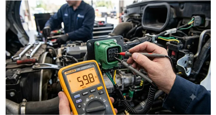
I’ll explain where 60 ohms comes from later. First, what I actually measured on that Ohio truck: 37 ohms across C and D. Not 60. Not 120. Thirty-seven. That number meant something was bridging the bus that shouldn’t have been there. It turned out to be a firewall pass-through connector whose sealing grommet had given up, letting road spray form a conductive path between the CAN pins. Once we pulled the connector apart, the resistance jumped back to 59.8 ohms. That’s how I knew we’d found it.
For reference, a healthy J1939 backbone shows roughly 60 ohms because it has two 120-ohm terminating resistors in parallel—one at each end of the backbone. If you see 120 ohms, one terminator is missing or has gone open. If you see something much lower, like 30 ohms, you’ve got an additional unintended terminator, a module with a stuck bus driver, or moisture in a connector creating a resistive path. This single measurement catches more J1939 problems than anything else you can do with a multimeter.
Here’s a quick reference table for what you’ll find during resistance diagnostics:
| Measurement | Expected Value | What Else It Could Mean |
| CAN high to CAN low (power off) | 60 Ω (± a few ohms) | 120 Ω = missing terminator; <50 Ω = short or extra load |
| CAN high to ground | >1 kΩ (effectively open) | <1 kΩ = partial short; 0 Ω = hard short to ground |
| CAN low to ground | >1 kΩ (effectively open) | <1 kΩ = partial short; 0 Ω = hard short to ground |
| CAN high to battery positive | >1 kΩ (open) | Low reading = short to power |
| CAN low to battery positive | >1 kΩ (open) | Low reading = short to power |
Step 3: Resistance to ground and to power—finding shorts
With batteries disconnected, measure resistance from CAN high to ground, and CAN low to ground. Each should read kilohms or megaohms—effectively open. A reading below one thousand ohms suggests a partial short to ground. Zero ohms is a hard short.
Now do the same to battery positive. I’ve seen a pinched harness behind an engine ECM bracket short CAN high to a constant 12-volt supply. That module’s bus driver fought valiantly until its thermal protection shut it down. Resistance measurement found it before the melted insulation did.
If you find a low-resistance path to power or ground, start unplugging nodes one by one while watching the meter. When the short clears, you’ve found your bad actor or at least the branch of the harness that’s damaged.
Step 4: DC voltage with key on, engine off
Reconnect the batteries. Key on, engine off. Set your meter to DC volts. Probe CAN high and CAN low relative to ground.
A healthy idle bus sits at roughly 2.5 volts on both lines. If you see CAN high at battery voltage and CAN low at zero, you’ve got a short to power on the high side and a short to ground on the low side—or a dead transceiver. If one line is stuck high while the other idles normally, start looking for a failed node dragging the bus dominant.
Here’s a trick I’ve used many times: switch your meter to AC millivolts. A quiet bus will show very little AC content. If you see hundreds of millivolts AC, there’s active traffic, which means at least some modules are alive and trying to communicate. This doesn’t decode messages, but it confirms the bus isn’t completely dead. On that Ohio truck, seeing AC ripple told us the engine ECM was at least transmitting—narrowing the no-start to a different root cause entirely.
Step 5: Diode check mode for transceiver health
Few people mention this, but a diode test across CAN high to ground and CAN low to ground can reveal a damaged transceiver’s ESD diodes. With the connector unplugged from the device under test, put your meter in diode mode. Measure from CAN high to ground, then reverse the leads. You should see a diode drop (around 0.5 to 0.7 volts) in one direction and open in the other. Same for CAN low. If you get a short or open in both directions, that transceiver is physically damaged.
I found a faulty DEF dosing controller this way on a Canadian grader. The module would pass a visual inspection, it would power up, but it corrupted the whole bus. Diode test caught it in under a minute.
What the multimeter absolutely cannot tell you
Let’s be brutally honest about the limits of multimeter-based J1939 diagnostics. You cannot see individual bits, frame errors, or bit stuffing. You cannot measure propagation delay or identify an intermittent node that fails only when vibration hits. You cannot decode suspect parameter group numbers that might point to a specific faulty sensor. For those, you need a scope or a J1939 interpreter.
A multimeter also averages. Intermittent bus-off events that last microseconds won’t register on a DMM. I’ve chased a machine that would sporadically lose the transmission controller. The multimeter said the bus was fine. A scope showed a two-microsecond glitch caused by a connector fretting at a specific RPM. Tools have their place.For those intermittent harness opens that only appear under vibration, I’ve documented a systematic wiggle test protocol that finds them without guesswork.
Mistakes I’ve watched turn a diagnosis into a parts cannon
I watched a shop foreman condemn an engine ECM because his resistance reading was 22 ohms. He’d left the batteries connected. The ECM’s internal pull-up was skewing the measurement. Four thousand dollars in parts were already ordered by the time I pointed it out. Disconnect the batteries every single time you put a meter on the CAN bus. No exceptions.
On a European loader, a tech assumed the diagnostic connector pinout was standard. He had CAN high and CAN low swapped on an aftermarket telematics unit. The bus looked completely dead on voltage, but it was just cross-wired. Two hours of head-scratching because nobody checked the diagram for that specific model year.
I’ve seen someone use an old analog multimeter with 1-megaohm input impedance to check CAN voltage. The meter loaded the bus enough that idle voltage read 1.8V, and the technician started replacing modules. A 10-megaohm DMM is the minimum; anything less lies to you.
Combine harvesters are brutal on connector shells. One machine had a cracked Deutsch backshell on the engine ECU connector. DC resistance and voltage were perfect, but EMI from the alternator kept knocking the transmission controller offline. The shell is part of the shield—treat it that way.
And I’ve lost count of how many clusters and ECUs get condemned because one resistance or voltage measurement looked off. On a Freightliner, the instrument cluster was dead on the bus. Voltage at the cluster connector showed 2.5V on both lines—but the problem was a chafed wire inside the dash, three feet from the cluster. They’d already priced a replacement cluster for over a thousand dollars. Always trace before you replace.Ground offset is a silent network killer I’ve covered in depth separately—here’s how to diagnose it when your multimeter alone isn’t giving you the full picture.
How to know the fix actually worked
After we scraped the green corrosion off those firewall pins and packed the connector with dielectric grease, we hooked the batteries back up and put the meter on C and D: 59.8 ohms. Key on—2.49V on CAN high, 2.51V on CAN low. The driver turned the key, and that Series 60 lit off faster than it had in weeks. I still made him run it up to operating temperature while I watched for any J1939-related DTCs in the instrument cluster. Nothing came back. No parts replaced. One technician’s pride restored.
Some hardware I built after that Ohio call
After that Ohio call, I built a dozen small breakout harnesses that permanently live in our service kits. They have Deutsch connectors on one end and color-coded flying leads on the other, potted so moisture can’t wick into the wire strands. No more piercing insulation with backprobes. No more holding meter leads at awkward angles under a dash.
We’ve since refined the design and now build these for field techs and fleet maintenance teams. The production versions, like our J1939 pigtail breakout cable, give you labeled pigtails for CAN high, CAN low, power, and ground—sealed, overmolded, and built to survive a toolbox environment. For shops that want to go further, we also supply bulkhead pass-through adapters and custom-length J1939 backbone extensions. Every cable assembly goes through continuity testing, insulation resistance testing, and a full physical inspection before it leaves our production floor. That’s backed by IATF16949 process controls, RoHS-compliant materials, and in-house overmolding capabilities that most resellers don’t have.
If you’re dealing with mixed fleets or oddball connectors, we can design a one-off diagnostic harness that matches your exact pinout, connector brand, and wire gauge. No minimum quantity theatrics. You tell us the problem, we build the cable, you get back to making machines run.
Questions that tend to come up after these calls
Can I use a test light instead of a multimeter?
A test light pulls anywhere from 150mA to 300mA. A CAN transceiver’s output driver isn’t designed to source that. I’ve personally replaced a fried BCM that a technician accidentally shorted CAN high to ground with an incandescent test light. The pop was audible. Use a 10-megaohm DMM, period.
What should the AC voltage reading be on a healthy J1939 bus?
On a Detroit DD15 running at high idle, I logged about 340mV AC on the Fluke 87V’s autorange setting. On a quiet bus with only the ECU awake, it dropped below 80mV. Those numbers aren’t in any spec sheet I’ve seen, but they’ve become my personal reference for J1939 bus activity. If I see zero AC with the key on, I know the bus is silent.
My resistance measurement shows 0 ohms between CAN high and ground. What next?
Start unplugging modules. A hard short often traces to a wire rubbed through against the chassis, or a connector filled with conductive debris—I once found a caterpillar harness where a bolt had pierced the loom and welded itself to the CAN high conductor. Divide and conquer.
Does the engine need to be running for these tests?
Most resistance and key-on idle voltage tests are done with the engine off. Running the engine can be useful for confirming bus activity, but never disconnect or reconnect modules with the engine running—ECMs don’t appreciate hot plugging. I’ve seen an ECM shut down permanently from a voltage spike during a hot unplug.
Why does my J1939 connector have different pin letters than what’s written here?
Some OEMs deviate. Always cross-reference the specific vehicle’s wiring diagram. The SAE standard is widely followed, but exceptions exist in construction equipment and gensets. I carry a laminated card with pinouts for five different OEMs just to save time on service calls.
Can I diagnose termination resistor problems with just a voltage measurement?
Voltage can hint at it—an open terminator often shifts idle voltages slightly—but resistance measurement across C and D is definitive. I once spent an hour chasing a 0.3V offset that turned out to be a missing terminator. Should have just grabbed the ohmmeter first.
Is it safe to pierce wires to backprobe?
Piercing insulation invites moisture and corrosion. Use a proper breakout harness or terminal backprobe kit instead. We build breakout cables specifically to prevent harness damage during diagnosis—after too many wiring harnesses got ruined by backprobe pins.
My bus shows 60 ohms and 2.5 volts, but I still have communication errors. Now what?
You’re past what a multimeter can see. Likely candidates: intermittent connector fretting, EMI, or a module that’s babbling at the wrong baud rate. Time to bring in a scope or J1939 analyzer. That’s the hard truth.
Can a multimeter help find which module is flooding the bus?
Indirectly. Unplug nodes one at a time while watching the AC millivolt reading. If traffic suddenly drops significantly when you unplug a particular module, that module may be over-transmitting. It’s not foolproof, but it’s a clue. On a bus where the transmission ECU was hammering the network, I saw AC drop from 480mV to 90mV as soon as we pulled that module’s fuse.
If you need a diagnostic harness that doesn’t exist yet
We’re not a catalog-only shop. If you’re chasing J1939 communication faults across different machines and need a custom diagnostic adapter—specific lengths, specific connectors, specific labeling—send us the details. Our engineering team does OEM cable customization daily. That includes logo printing, custom overmolding, wire gauge specification, and sealed connector assemblies that hold up to road salt, hydraulic oil, and pressure washing.
You can reach us directly on WhatsApp for a one-on-one engineering discussion, or use the contact form on our site. No price lists here. No shopping carts. Just a conversation about what you need and whether we can build it.
WhatsApp: Start a conversation
Contact page: Send us your requirements
Twenty-plus years of building cables. ISO 9001, ISO 14001, IATF16949. Every assembly tested. Four inspection gates before it leaves. No exceptions.
