

I still remember the call from a fleet manager in Edmonton who had fifteen trucks sitting dead on the yard. The fault was the same on every unit: “J1939 communication lost – engine derate.” His shop had already replaced the engine ECM, two cab controllers, a complete chassis harness, and a handful of dash clusters over the previous month. The total parts bill had crossed forty-two thousand dollars, and the trucks still wouldn’t move reliably. When a tow truck brought one of those rigs into our diagnostics bay, I measured the backbone resistance at the 9-pin diagnostic connector and got 94 ohms with the battery disconnected. There was a single corroded terminating resistor hidden inside the frame rail near the DEF tank. The fix took seventeen minutes, and the truck drove out under its own power. That’s what I call the parts cannon — and it’s the most expensive tool in any fleet’s toolbox.
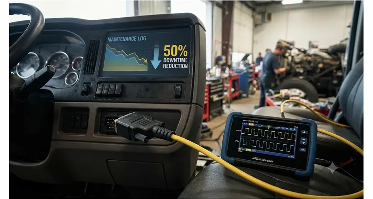
I’ve watched more than a few sharp technicians walk straight into the parts cannon trap, not because they lack skill, but because the SAE J1939 physical layer doesn’t fail the way a mechanical component does. You can’t see an impedance mismatch the way you can spot a cracked bracket. A floating shield doesn’t leave a drip pan stain. Micro-fretted pins hide inside sealed connectors until the network starts gaslighting you with random derates. You need a structured diagnostic workflow that treats the entire network as one system before you condemn any single node. After adopting that mindset, a refuse fleet we worked with reduced its average electrical-related vehicle downtime from three days per incident to just under one and a half days — a 50% downtime reduction that stuck for two consecutive years. Here is the exact J1939 diagnostic workflow that made that possible, step by step.
Why the Parts Cannon Always Wins If You Let It
J1939 rides on the CAN bus physical layer, and that foundation demands precise termination and topology — there’s no room for guesswork. I’ve taught enough J1939 classes to recite the spec in my sleep: two 120-ohm resistors at the farthest ends of the backbone, parallel down to 60 ohms when the key is off. Stubs under a meter. Clean, simple, and rarely what’s actually out there. The Edmonton truck proved that corrosion doesn’t just nibble at resistor leads. It migrates inside the molding compound and turns a 120-ohm terminator into a 94-ohm humidity sensor that drifts with temperature — exactly the kind of failure that drifting termination resistance can mimic on a hot engine. A standard unpowered resistance check caught it. A less stubborn diagnostic path would have replaced the engine ECM for the fourth time.
Intermittent J1939 faults never announce themselves with a convenient label. They show up as subtle, maddening violations — corrosion creep inside a sealed connector that adds tens of ohms of contact resistance, a 270-ohm split termination someone installed because a forum post said it would reduce noise, or a floating shield that turns your differential bus into an antenna for alternator ripple. When SPN 639 – J1939 Network #1 pops up on the scan tool, the diagnostic tree tells the technician to check power and ground, then condemn the ECU. That’s the tripwire for the parts cannon. The real culprit lives in the wiring, the connectors, or the backbone topology — almost never inside the ECU enclosure. If you’ve ever been burned by a phantom derate that disappeared after a key cycle, you already know how an alternator ripple problem can masquerade as a dead network.
The Structured J1939 Diagnostic Workflow
The following workflow assumes you have a decent multimeter with min/max recording and an oscilloscope or a dedicated CAN bus tester. It treats the network as a single instrument — measure first, disconnect nodes second, replace nothing until you have proof. Every step in this J1939 diagnostic workflow has saved me from firing the parts cannon at least once.
Step 1: Look Before You Meter — Connectors Lie More Than ECUs
Before you touch a meter, pull every 9-pin diagnostic connector and the termination caps under a bright work light. What I’m looking for is subtle:
- Green or white powder inside the connector cavity (copper sulphate or zinc oxide).
- Pins that sit slightly lower than their neighbors when viewed end-on — classic backed-out terminal.
- Seal rings that have turned rigid or cracked, a sign that road de-icer has been wicking along the wire strands.
A long-haul tractor once taught me a two-week lesson about trusting visual inspections. I was chasing an intermittent derate and finally found a Deutsch connector that looked factory-fresh outside. Inside, the socket had lost its gold flash and developed a 40-millivolt contact resistance drift when warm. I only spotted it because I happened to test through a known-good breakout harness — one that had been built on an IATF16949 line with a 4-step quality check: continuity, insulation resistance, pin retention, and signal integrity under load. When a breakout adapter adds its own ghosts to the measurement, you’ll chase phantom faults for days — the same reason a scan tool can’t see the network when the adapter pins are worn. Field repairs rarely match that consistency, which is why I now carry sealed, overmolded breakouts — like our J1939 9-pin pigtail breakout cable that lets me probe safely without ever touching the OEM wiring — and insist on physical inspection through a verified interface.
If you find any connector that looks suspect, don’t just “clean it and hope.” Replace the terminal and seal or use a verified bypass adapter for test purposes. A single pin with 30 ohms of series resistance can drag the differential voltage below the CAN recessive threshold intermittently, and you’ll spend weeks chasing ghosts.
Step 2: The 60-Ohm Rule and Its Three Favorite Lies
Turn the master disconnect off. I always wait until the ECUs power down completely — watch the J1939 voltage decay to zero on a scope if you have one, or give it a couple of minutes. Then measure resistance between pin C (CAN High) and pin D (CAN Low) on the 9-pin Deutsch connector. The table below shows the Deutsch pinout with field notes I’ve collected from real failures.
| Pin | Function | Typical Wire Color | Field Note (Edmonton Lesson) |
| A | Ground | Black | If pin A measures >0.2V drop from battery negative under a 5A load, fix frame grounds before any CAN measurement. |
| B | Battery (+) | Red | — |
| C | CAN High | Yellow | On some 2015–2018 engine families, this wire changes to orange at the pass-through bulkhead — don’t assume color consistency. |
| D | CAN Low | Green | — |
| E | Shield (drain) | Bare/Black | Many body builders leave the shield drain floating near the tail lamps. This turns your CAN bus into a single-turn antenna for alternator ripple. |
| F | SAE J1708 (+) | White | — |
| G | SAE J1708 (-) | Blue | — |
You should see 60 ohms ± 10%. If you see 120 ohms, one terminator is missing. If you see open or > 1 kΩ, both terminators are gone or you have a broken backbone wire. If you see something like 40 ohms, someone has added a third resistor, and you need to find it and remove it. This is the foundational 60-ohm backbone design that every J1939 network depends on. I once found a 60-ohm reading that drifted to 84 ohms when you wiggled the cab tilt hinge — the backbone wire had snapped inside the insulation right at the hinge point. The multimeter’s min/max recording mode caught the jump while I moved the harness. Without that record, I would have been back to guessing.
Step 3: The 2.5-Volt Baseline That Tells You Where the Gremlin Sleeps
With the ignition on and network alive, measure DC voltage on CAN High and CAN Low referenced to pin A (ground). A quiet J1939 bus should sit at roughly 2.5 V on both lines — that balanced baseline tells you the bias is correct. Once data starts flowing, CAN High pulses to about 3.5 V and CAN Low drops to about 1.5 V, giving a clean 2 V differential dominant state.
Red flags that I’ve learned to respect:
- CAN High reads 4.8 V and CAN Low reads 0.2 V: you’re measuring on the wrong side of a lost ground reference.
- Both lines float around 1.8 V: one CAN transceiver is in a permanent dominant state, dragging the whole bus down. Unplug nodes one at a time until the voltage returns to 2.5 V recessive — but do this with the master disconnect off first to avoid a voltage spike.
- CAN High and CAN Low are identical within 50 mV even when the engine is running: the bus is stuck in recessive because something is holding it there, or your meter leads are on the wrong pins.
Step 4: Why Your Multimeter Needs a Scope Partner
I can’t count the number of times a DMM told me the bus was fine, only to find error frames stacking up on a scope. Multimeter averaging hides intermittent events completely. A scope set to 1 V/div and 100 µs/div will show you exactly what shape the bits are taking. On a clean J1939 bus, the square waves have sharp edges and a flat differential plateau. Things that should make you stop and dig deeper:
- Rounded shoulders on the recessive-to-dominant transition: excessive capacitance, often from a stub that’s too long — a design oversight I’ve seen create phantom faults that cost thousands per truck annually.
- Ringing or overshoot of more than 500 mV on edges: missing or damaged termination.
- Narrow spikes riding on the recessive level: arcing from a failing voltage regulator inside an alternator, coupling into the harness inductively.
- Error frames appearing as a burst of six consecutive dominant bits: these won’t trigger a DTC immediately, but they throttle throughput and can eventually cause node timeouts.
A quality oscilloscope waveform diagnostic session will expose these gremlins in minutes. I use a two-channel scope with differential math so I can see the CAN waveform and a single-ended channel on the shield line simultaneously. If the shield shows voltage pulses relative to battery ground, you’ve got a ground offset problem. Fix the frame grounds before you chase any ECU.
Step 5: Disconnect Nodes Last, Not First
Only after you’ve verified the backbone is electrically sound do you start disconnecting nodes. My sequence:
- Disconnect all nodes except the engine ECM and the diagnostic connector.
- Verify the network comes up with just those two points (60 Ω, correct voltages, clean waveform).
- Add nodes back one at a time, watching for any change in resistance, bus voltage, or waveform shape.
- When the network degrades, you’ve found the offending node — or the stub harness connected to it.
This step catches damaged CAN transceivers, but far more often it catches a chafed stub harness that shorts CAN High to chassis bracket only when the truck hits a specific vibration frequency. That’s the kind of fault that would have cost another engine ECM and a transmission controller if you’d stayed on the parts cannon path. In fact, a transceiver can fail and still partially communicate, so never assume a “talking” node is healthy.
Common Mistakes That Prolong the Pain
I once walked into a shop and saw a foreman probing a J1939 backbone with an incandescent test light, looking for “voltage.” The bulb filament drew 400 milliamps — about ten times what a typical transceiver pin is rated to source. One flash, and the transmission ECU’s CAN controller locked into a permanent dominant state. That no-crank complaint turned into a four-thousand-dollar transmission controller replacement. If you need to check for voltage presence on a J1939 backbone, use a high-impedance DMM, period. A 3-watt bulb has no business near a 250-kbps differential bus.
A technician I worked with probed a CAN High wire with a T-pin during a roadside repair. Six months later, that pinhole had wicked enough road salt solution into the copper to rot three inches of conductor inside the insulation. The truck came back with an intermittent no-start that took four days to isolate. If you must back-probe, use a sealed breakout harness with flying leads — never violate the insulation.
On one mixer truck, the rear termination cap behind the tail light had filled with brine over two winters. The resistor measured 178 ohms and drifted with humidity. The truck would run fine in dry weather and shut down after every rainstorm. It took three ECUs before someone pulled that cap. Fleets that don’t inspect termination caps during PM services are inviting this exact failure — a mistake I’ve seen cost over twenty-three cents in resistor replacement but tens of thousands in downtime.
Fitting a generic 120-ohm resistor from an electronics shop is another trap. A carbon-film resistor will measure 120 ohms on the bench. Put it through a thousand thermal cycles on a chassis rail and it’ll drift to 150 ohms, then crack open. J1939 needs metal-film or wire-wound parts rated for the pulse energy of a 250-kbps bus.
And the most expensive assumption: thinking a “communication lost” DTC means the ECU is dead. In fourteen years of diagnostic work, I’ve replaced fewer than five ECUs for a true CAN transceiver failure. The rest were wiring, termination, or ground faults that a structured test would have caught.
How to Confirm the Fix Sticks
My closure test isn’t a quick road test. It’s an electrical stress test. Clearing the fault code and driving around the block won’t tell you if the network can handle full load. Here’s what I do:
- Run the engine at high idle and activate every high-current load simultaneously: headlights, HVAC blower, electric cooling fans, grid heaters, wipers.
- While everything is loaded, record a 10-second scope capture. The waveform should show no additional noise, no error frames, and zero voltage offset drift.
- Perform a wiggle test on every connector and backbone branch while streaming J1939 messages with a diagnostic tool. Watch for dropped messages or bus-off events. A formal wiggle test protocol turns this from a random shake into a repeatable diagnostic step.
Only when the network remains stable under maximum electrical stress do I consider the repair closed. This is exactly why I rely on breakout harnesses that have passed continuity, insulation resistance, pin retention, and signal integrity tests under load — not the loose-socketed adapter from the bottom of a service truck drawer. A single unreliable connection in the test path can mimic a network fault and send you down a wrong diagnostic path.
Real-World Outcome: 50% Downtime Reduction in Numbers
The refuse fleet I mentioned operates 120 trucks across six sites in the Midwest. Before adopting this structured J1939 diagnostic workflow, their average diagnosis time for an electrical fault that triggered a J1939 derate was three days. Parts cost per incident averaged eight thousand seven hundred dollars. After training their lead technicians on the workflow and equipping each shop with proper breakout harnesses and scope setups, their mean time to repair dropped to one point four days. Their annual spend on misdiagnosed electrical components dropped by over one hundred sixty thousand dollars. The downtime reduction is a direct 50% when you measure truck-availability hours — and that’s not a projection; it’s their service log data. The fleet now tracks electrical repair time as a KPI, and the numbers hold. For a deeper look at the return on investment, see how a basic physical-layer toolset can cut downtime by 70%.
What You Need in Your Diagnostic Kit
You don’t need a truckload of equipment, but the quality of the interfaces matters as much as the quality of the meter. I recommend:
- A CAT III rated multimeter with min/max recording.
- A 2-channel oscilloscope with at least 20 MHz bandwidth and differential capability.
- A J1939 diagnostic interface that can display bus load and error frames.
- A set of sealed breakout adapters that match the fleet’s connector ecosystem — 9-pin Deutsch, OBD-II style J1939, and OEM-specific connectors.
We manufacture those adapters and custom harnesses directly at our own facility. Because we handle OEM customization — logo, brand, cable length, color, wire AWG — without minimum orders, many fleets standardize on harnesses built to their exact spec. The same 4-step inspection that catches a 40-millivolt socket drift in the factory means the adapter you plug into a truck doesn’t add its own story to the diagnosis.
Frequently Asked Questions
1. What is the single most overlooked cause of intermittent J1939 faults?
Fretting corrosion on the mating faces of sealed connectors, often from vibration and thermal expansion. A transit bus fleet was chasing intermittent ABS dropouts for months. The fault disappeared every time they reseated the ABS ECU connector, so they assumed it was a software glitch. Under a microscope, the tin-plated terminals had micro-fretted to a black oxide. Replacing the terminals and applying a quality contact lubricant ended the issue for good. If a fault vanishes when you reconnect a plug, suspect the oxide layer you just wiped away.
2. Can I use a regular OBD-II reader on a heavy-duty J1939 9-pin connector?
You need a physical adapter and a protocol converter. I’ve had shops plug an ELM327 Bluetooth dongle into a 9-pin adapter and wonder why they’re seeing garbage data. The hardware can see the bits, but the ELM327 firmware doesn’t understand 29-bit identifiers or J1939 transport protocols. You need an interface built for heavy-duty parameter groups, not a generic OBD-II scanner.
3. How do I measure terminating resistor values if I can’t access both ends of the backbone?
Disconnect one node at a time and measure at the 9-pin diagnostic connector. You’ll see step changes in resistance as you disconnect the node that carries one end of the terminator. Expect the resistance to jump from 60 Ω to 120 Ω when you unplug the node that contains the distant terminator. This method saved me on a concrete pump where the rear termination was buried behind twelve feet of hydraulic piping.
4. Is it safe to hot-plug nodes into a live J1939 network?
J1939 is designed to tolerate node connection and disconnection under power, but I avoid it during diagnostics. I once caused a bus-off event on a 2007 engine ECU by hot-plugging a diagnostic connector while the key was on. The ECU interpreted the rapid connection bounce as a network failure and locked out communication until the batteries were disconnected for ten minutes. It added three hours to a routine inspection.
5. What voltage should I see on the shield pin relative to ground?
Ideally, less than 0.1 V DC difference. I measured 1.2 V on a shield line once — turned out a battery ground cable had corroded to the point of a 0.6 V drop under cranking, and the shield was carrying the return current for the DEF heater. That offset was enough to corrupt CAN messages every time the DEF system powered up. Investigate frame bonding straps and battery-to-chassis grounds.
6. My J1939 works perfectly until the engine warms up, then drops nodes. What should I check?
Thermal expansion is opening a dry solder joint in a terminating resistor pack, or a marginal crimp inside a connector body. Use freeze spray on suspect resistors and connectors while monitoring CAN bus traffic. On a delivery truck, I pinpointed a terminator that went open-circuit at 160°F exhaust pipe temperature — ten degrees below normal operating heat. A five-dollar freeze spray can saved another ECM.
7. Can a faulty battery or alternator cause J1939 communication errors?
Absolutely. Alternator ripple that exceeds 100 mV AC is a known cause of bit errors on CAN buses. On a long-haul truck, the CAN bus would fail after 4 hours of driving. The scope showed a 150 mV AC ripple on the DC baseline at exactly the alternator’s frequency. Replacing the rectifier bridge inside the alternator fixed it permanently. Test the charging system before touching the network.
8. How many nodes can a J1939 backbone support?
The specification says up to 30 nodes at 250 kbps. In practice, I’ve seen a refuse truck with 23 nodes start throwing intermittent bus-off errors every time the electric cooling fan kicked on. The problem wasn’t bus loading in the protocol sense — it was the inrush current sagging the supply voltage at the farthest node, momentarily pulling its transceiver out of spec. Adding a dedicated power stud and capacitor bank at the rear termination cured it. Node count is a paper limit; voltage drop across the backbone is the real governor.
9. Should I add a third terminating resistor if the backbone is longer than 40 meters?
No. Adding a third 120-ohm resistor doesn’t just “split the load.” It pulls the differential voltage down to about 1.3 V, right at the edge of the CAN transceiver threshold. Any noise on top of that flips bits. That’s why you never stack terminators. If you need longer runs, consider a different topology or a bridge.
10. Can a custom diagnostic harness really improve first-time fix rate?
Yes. When every tech in the fleet uses the same sealed breakout kit, you eliminate the variable of “creative” probing methods. I’ve seen shops go from a 30% first-time fix on electrical issues to over 80% just by standardizing the test interface. A custom diagnostic harness that gives you safe tap points without piercing the OEM wiring ensures you’re measuring the actual network state, and it reduces procedural variation across multiple technicians.
Engineering Support Without the Pitch
Whether you’re trying to tame a fleet-wide J1939 gremlin or you’re specifying diagnostic breakout harnesses for a production line, the network layer only cooperates when your physical connection is right. We’re an IATF16949-certified and ISO 14001-certified factory with over 20 years of experience building components for heavy-duty networks. We handle OEM customization — logo, brand, length, color, wire AWG — without catalog push or minimum order pressure. Whether you need a single custom harness or a container of OEM-specific diagnostic adapters, you’re talking to the same team that builds them. If you need a custom harness that matches your fleet’s connector mix, or you want to discuss an OEM-specific diagnostic adapter project, reach out directly to our engineering team.
Chat with us on WhatsApp: https://api.whatsapp.com/send/?phone=8617307168662&text=Need+Help%3F+Chat+linda+WhatsAPP&type=phone_number&app_absent=0
Contact Page: https://obd-cable.com/contact/
No scripts, no catalogs — just a direct line to the people who build the product.
