

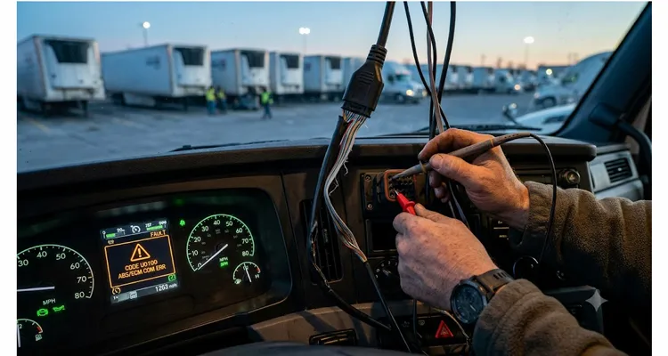
The call came in on a Tuesday. A fleet manager in the Midwest had thirty-seven reefers experiencing intermittent instrument cluster blackouts, ghost fault codes, and two trucks that refused to regen at the same distribution center. The OEM dealer had already swapped the instrument cluster, replaced the engine ECU on one unit, and billed forty-one thousand dollars in parts and labor. Nobody suspected the three-month-old telematics gateway plugged into the diagnostic connector — until we scoped the bus.
That scenario isn’t rare anymore. It’s quietly scaling across mixed fleets as aftermarket telematics, ELDs, and asset trackers multiply on J1939 networks that were never designed to host half a dozen parasitic nodes. The reliability cost is real, but it rarely shows up on a balance sheet as “telematics-related.” It shows up as unscheduled downtime, misdiagnosis, warranty friction, and a slow erosion of trust in perfectly good hardware. We’ve documented the mechanics of this aftermarket telematics J1939 reliability cost across multiple fleets — the pattern repeats with almost mathematical consistency.
I’ve spent the better part of two decades on the manufacturing side of diagnostic and vehicle network connectivity — not in a sales office, but on the test bench and inside supplier audits where harnesses get dissected. What follows isn’t a generic guide. It’s the technical layer most blog posts skip.
The silent failure mode most fleets inherit by accident
Most fleets don’t inherit a J1939 fault on day one. They inherit a marginal bus that tolerates the telematics device — until a high-vibration highway segment, a wet connector, or a DOC regeneration burst pushes the error counters past a threshold the ECU firmware can’t ignore. The physical layer defined by the SAE J1939 standard calls for 250 kbps, 120 Ω differential impedance, dominant-recessive swing of roughly 2 V. But the field reality we measure during harness audits rarely matches the textbook. A two-meter stub piggybacked onto the diagnostic connector with no local termination shunts the impedance low enough that the recessive level drifts outside the transceiver’s common-mode range. We’ve captured that drift at 380 mV — not a bus-off yet, but enough that a single missing ACK slot during an aftertreatment dosing handshake triggers a ghost fault the dealer’s diagnostic software misattributes to the DEF controller.
The Molded Y-Splitter: A Common J1939 Harness Failure Mode
The most common damage vector I see is a telematics interface cable that treats the J1939 backbone like a casual three-wire tap. A typical offender: a molded Y-splitter that plugs into the 9-pin diagnostic port, routes CAN Hi, CAN Lo, and ground to a DB9 or flying leads, and ignores shield continuity, proper stub length, or termination state. If that splitter adds a two-meter stub without a dedicated terminating resistor, the lumped impedance shifts. Signal reflections begin. Bus loading creeps beyond the transceiver’s capability on some nodes, especially during high-traffic bursts like a DOC regeneration event. The mathematics behind these reflections — and how they corrupt the bit sampling point — is detailed in our breakdown of J1939 stub length reflection timing.
None of this triggers an immediate MIL. The network doesn’t just “fail.” It limps along on active error frames and automatic retransmission until a critical message — wheel speed, accelerator pedal position, aftertreatment dosing command — gets delayed or dropped. The technician reads a fault code pointing to a sensor or actuator, and the telematics box remains invisible because it’s not an addressable node on the diagnostic tree.
What a degraded bus actually looks like on a scope
On a scope, a properly terminated J1939 segment settles from dominant to recessive inside 80 ns with negligible rebound. When we probed the Midwestern fleet’s bus with the aftermarket gateway connected, the transition showed a 220 ns ringback envelope and a 380 mV bump on the recessive level — not from a failing ECU transceiver, but because the harness stub presented an unterminated impedance discontinuity roughly 1.9 meters from the diagnostic port. That distortion alone added enough bit error rate that the engine ECU’s CAN controller hit its warning limit within four minutes of key-on. No DTC set for “network error.” The only symptom was an intermittent accelerator pedal rationality fault that appeared and vanished on different drive cycles.
A 15 mV Ground Shift and Node Bus-Off
I’ve also watched a different failure play out in real time on a PicoScope. The vehicle idled perfectly — until the HVAC clutch engaged, ground shifted fifteen millivolts, and the telematics node fell off the bus entirely. The harness looked fine on a continuity tester. The scope revealed the truth: the floating shield and untwisted pigtail had turned the J1939 cable into a noise antenna that collapsed the bit sampling window the moment a high-current load switched on. Even a ground shift this small can mask as a sensor failure; we’ve measured a 0.3V ground offset on a J1939 backbone that cost one fleet nine thousand eight hundred dollars before the root cause surfaced.
Root cause isn’t the telematics device — it’s what connects it
Most telematics units themselves use competent transceivers. The problems concentrate in the physical interconnect: wire gauge, twisting, shielding, termination strategy, connector metallurgy, and pin assignment. When a fleet procurement manager buys a device based on cellular subscription cost and never audits the wiring harness that comes in the box, the fleet inherits whatever the device OEM’s lowest-bidder supplier shipped that quarter.
Four Root-Cause Patterns from Supplier Audits
Over the last decade, we’ve categorized field failures into four root-cause patterns we call out during supplier audits. Each one is traceable to a single assembly decision made without understanding what the CAN bus actually needs.
- Cable type substitution — flat ribbon where twisted shielded pair is specified. This destroys differential noise rejection. I measured common-mode rejection degradation of 18 dB compared to a proper 20 AWG twisted pair with 12 turns per foot. Even a 12 percent cable asymmetry can introduce common-mode noise that corrupts J1939 communication.
- Shield termination omission — floating drain wire turns the shield into a radiator instead of a Faraday cage, particularly in proximity to VHF two-way radios or high-current compressor wiring. When the shield isn’t grounded, common-mode voltage shifts kill J1939 communication without leaving a trace in the fault log.
- Stub violation — exceeding the SAE J1939/11 recommendation of 1 meter for 250 kbps. Many installations end up with 2.5 meters simply because the installer routes the J1939 cable under the dash and up the A-pillar to a roof-mounted antenna. The timing math is unforgiving: the longer the stub, the later the reflection arrives, collapsing the bit sample window.
- Power/ground contamination — using pin C (battery) without a dedicated return. The voltage drop on the ground pin tilts the bus common-mode voltage, which some transceivers tolerate and others don’t. We’ve pulled together a dedicated J1939 ground offset voltage diagnosis walkthrough because this pattern wastes more diagnostic hours than any other physical layer issue.
The fleet in the Midwest I mentioned earlier? The harness was a generic OBD-II extension cable repurposed for J1939, with a molded 16-pin connector that only populated pins 6 and 14 (CAN Hi/Lo) and pin 4 (ground) — no shield, not twisted, no termination. The 9-pin Deutsch diagnostic connector on the truck had an internal 120 Ω resistor between CAN Hi and Lo inside the vehicle harness, but the telematics cable added a bare stub that introduced an impedance discontinuity. A thirty-nine-cent part triggered a forty-one-thousand-dollar diagnostic goose chase.
When we see fleets struggling to access the 9-pin diagnostic port cleanly without degrading the bus, we often point them toward a proper J1939 9-pin pigtail breakout cable — not a generic splitter, but a purpose-built harness that preserves shield continuity and termination. For installations in cramped dash panels where a standard straight connector forces a sharp bend radius on the CAN twisted pair, a J1939 90-degree right-angle cable with Deutsch DT connectors eliminates the mechanical strain that eventually fractures conductors and creates intermittent opens.
Specification checklist for a telematics J1939 harness that won’t degrade the bus
If your fleet runs aftermarket telematics on commercial vehicles, or if you manufacture telematics hardware and want to stop fielding mystery support tickets, the physical interface requires the same rigor as any other vehicle subsystem. Here is what we require on the production floor — phrased as pass/fail criteria any procurement engineer can audit.
- Twisted pair impedance: 120 Ω ± 10% at 250 kbps, verified on a network analyzer per batch. We use 20 AWG (18 AWG for backbone extensions) with a tight twist pitch — 12 turns per foot — bare copper, in a shielded jacket. The twist isn’t cosmetic; it equalizes induced noise across the two conductors.
- Shield grounding topology: Single-point chassis ground at the diagnostic connector. Shield continuity verified; no second path through a bulkhead or device chassis. Breaking this rule invites ground loops that have collapsed entire bus segments in our field audits.
- Maximum stub length from backbone tap: ≤ 1.0 m for 250 kbps. If the telematics antenna location demands a longer run, the harness must be treated as a backbone segment with its own 120 Ω termination and split-termination network to maintain common-mode stability. Ignoring this rule is how a 23-cent resistor decision costs a fleet thousands.
- Connector contact metallurgy: Gold flash over nickel, minimum 0.4 µm Au on mating surfaces. This prevents the intermittent high-humidity failure where nickel-plated contacts develop contact resistance, trigger bus faults in wet weather, and self-heal when the weather dries out — the worst kind of intermittent to troubleshoot. Deutsch DT, HD10, or M12 connectors are standard.
- End-of-line electrical test: 100% continuity, pin-out, shield integrity, and TDR impedance check on every cable assembly. Batch testing doesn’t cut it. We learned early that a single mis-pinned CAN Hi/Lo pair can bring down a production vehicle at an upfitter’s facility six time zones away, and the cost of that mistake is always orders of magnitude larger than the cable.
Where the factory piece fits — without the brochure language
We run the cable manufacturing side of this equation. Not a reseller, not a trading company — a factory with twenty years of building vehicle diagnostic and network harnesses, currently operating under ISO 9001, ISO 14001, and IATF 16949 quality management. All materials are RoHS-compliant and CE/UL/REACH where applicable. The floor follows 5S discipline. Our IATF 16949 certification and ISO 14001 environmental management system are embedded in every process, not just framed on a wall.
Climate-Controlled Storage: A Lesson from a Canadian Logging Fleet
One thing that separates a factory floor from a trading company’s warehouse: climate-controlled raw material storage. We learned that lesson after a production lot of PVC-jacketed twisted pair destined for a Canadian logging fleet became brittle at -35°C because the polymer absorbed humidity during monsoon-season warehousing before extrusion. Now all cable stock, connectors, and overmold compounds live in a 23°C ± 2°C, <50% RH environment from inbound inspection through finished goods. Every reel is traceable to a supplier lot number that ties back to our incoming QA report. Fleets operating in extreme environments can see how these failures unfold in the field by reviewing our forestry J1939 harness failure analysis and field repair strategies.
OEM Custom Harness Capabilities
The custom side is where engineering conversations happen. We regularly produce custom OEM harnesses with:
- Custom OEM branding, logo embossing, and color
- Specific AWG and insulation compounds for high-temperature engine bay routing
- Unique pin assignments, termination networks, and connector combinations
- Full-plastic overmold design (RoHS, no metal shroud) where weight and corrosion matter
- Every cable tested, every batch traceable to raw material lot
We don’t sell a “universal J1939 telematics cable” on a product page because universal cables are the root cause of half the issues described above. Instead, we work directly with telematics OEMs and fleet engineering teams to produce the exact J1939 cable the application requires. Often, the conversation starts with a schematic, a vehicle network diagram, and a scope capture. That’s the language our engineers work in.
Verification: how to confirm the problem is solved
When the correct harness is in place, validation takes fifteen minutes.
The Four-Step Bus Validation Sequence
- Measure DC resistance between CAN Hi and CAN Lo with the vehicle asleep. A properly terminated bus with one added device (that includes its own split termination) should read approximately 60 Ω — two 120 Ω terminations in parallel. If the reading is 120 Ω, a termination is missing. If it’s 40 Ω, there are too many.
- Probe the differential waveform at the diagnostic connector. Look for a clean dominant-to-recessive transition with minimal overshoot (<100 mV) and settling within 100 ns. If ringback persists, stub length or termination is still wrong. This waveform check alone, using a J1939 oscilloscope diagnostic approach, can confirm whether the bus has returned to a healthy state.
- Log error frames for ten minutes under full traffic. A healthy J1939 segment at 250 kbps with proper physical layer design should show essentially zero error frames. Any steady count means the physical layer still has a problem.
- Perform a ground-shift test. Introduce a 0.5 V DC offset between the telematics device ground and the chassis ground reference and verify bus operation. A properly designed isolated interface will tolerate this without frame loss. If the bus collapses, the ground offset is still capable of causing ECU misdiagnosis.
What the repair order doesn’t say
When I talk to fleet directors, I ask them to run a five-month query on unscheduled service events that resulted in a “no trouble found” or “reprogrammed and released” outcome, where the repair order mentions instrument cluster, DEF, aftertreatment, or transmission communication faults. The dollar amounts that surface are rarely trivial.
Real Fleet Cost Examples: ECM Replacements and Diagnostic Labor
I’ve seen a refrigerated carrier spend sixty-three thousand dollars in unnecessary ECM replacements across twelve power units before an external consultant — not me, a different engineer — pulled the telematics harness and scoped the bus. Another municipal fleet paid eighteen thousand dollars in diagnostic labor alone chasing a ghost fault that vanished when the add-on GPS tracker was disconnected for an unrelated reason. The return on investing in basic J1939 physical layer tools can cut downtime by 70 percent — the cost of doing nothing is always orders of magnitude higher.
This isn’t a telematics problem. It’s an integration problem. Telematics devices bring genuine value — fuel tracking, predictive maintenance, cold chain compliance — but their physical connection to the vehicle network is often treated as an afterthought. When it’s done right, the bus doesn’t notice the device at all. That’s the engineering target.
If you’re currently rolling out telematics across a fleet, or you’re engineering the next generation of connected vehicle hardware and need the physical layer to work the first time, we’re set up to help. No stock cable recommendation, no generic solution. Just an engineering conversation that starts with your network architecture and ends with a tested harness that doesn’t introduce new problems.
Discuss your J1939 interface directly with our engineering team:
- WhatsApp: Chat with Linda on WhatsApp
- Contact Page: obd-cable.com/contact/
We take OEM custom harness projects, small prototyping runs, and full production volumes under IATF 16949. All conversations start with the technical requirements — no sales script, no catalog pitch.
FAQ — questions I’ve answered from fleet engineers and telematics OEMs
Q1: Why does my OBD-II splitter cable work fine on a passenger car but cause regen faults on a heavy-duty truck with J1939?
Because a passenger car’s CAN bus typically runs at 500 kbps with a different physical layer and the OBD-II pins 6 and 14 align with the vehicle’s network. On a heavy-duty truck, the J1939 network uses a 9-pin Deutsch connector with CAN Hi on pin C, CAN Lo on pin D. A passive OBD-II splitter cable does not preserve the 120 Ω impedance, often leaves the shield floating, and creates a stub long enough to disrupt message timing. The symptom that surfaces most often: an active regeneration event fails because an aftertreatment dosing command gets delayed or dropped. The technician sees a regen fault, not a network fault.
Q2: What’s the difference between a J1939 backbone and a stub in physical terms?
The backbone is the main trunk line, typically 18 AWG or 20 AWG twisted pair, terminated at both ends with 120 Ω. A stub branches off the backbone without terminating at the branch point. Length restrictions apply: 1 meter max for 250 kbps, shorter for 500 kbps (J1939/14). The device on the stub should have a high-impedance input relative to the bus to avoid loading.
Q3: Why do my fault codes blame the aftertreatment system when the telematics device is the real problem?
The aftertreatment system relies on a set of J1939 messages with tight timing constraints. When bus errors accumulate, the diesel exhaust fluid dosing control unit may not receive the required messages within the expected interval and sets a timeout fault. The fault code logically points to the DEF controller, but the root cause is a physical bus problem that drops the message entirely. Technicians follow the diagnostic tree to the node that reported the fault, not the node that caused the message loss. One classic example we’ve traced: SPN 1761 (DEF Tank Level) with FMI 19 (Received Network Data In Error) appearing intermittently on a truck with zero DEF system faults. The telematics harness stub was reflecting messages, corrupting the DEF tank level message just often enough to set the fault.
Q4: Is a shielded cable always necessary?
On commercial trucks with high-current alternators, two-way radios, and inverter noise, yes. Unshielded twisted pair can work on a clean bench, but in-vehicle electromagnetic interference typically demands a shield with a single-point ground. Our standard recommendation is shielded cable for any J1939 harness longer than 0.5 meters outside a shielded enclosure.
Q5: What wire gauge do you recommend?
20 AWG for typical stubs up to 1 meter. 18 AWG for backbone extensions where the harness becomes part of the backbone. 22 AWG is acceptable only if the stub is under 0.3 meters and the environment is benign — but we rarely spec it because it increases resistance and reduces mechanical robustness.
Q6: Can your factory match an existing telematics connector pin-out exactly?
Yes. This is the majority of our OEM work. We take the telematics device datasheet or a sample unit, map the pins per your specification, add any necessary termination or isolation circuitry, and produce a documented harness assembly with a unique part number. The cables ship with inspection reports tied to that part number.
Q7: How do I know if a J1939 network problem is from the telematics install versus a genuine component failure?
Disconnect the telematics device and any associated harness at the diagnostic port or the backbone tap. If the symptoms disappear and bus error counters return to zero, the aftermarket interface is the cause. This is a simple test that should precede any expensive component replacement. We’ve seen it save fleets tens of thousands of dollars in a single afternoon.
Q8: What certifications should a J1939 harness supplier hold?
At minimum, the manufacturing facility should operate under ISO 9001. For passenger or commercial vehicle supply chains, IATF 16949 is the standard that most Tier-1s require. RoHS and REACH compliance matter for international shipping. CE and UL certifications apply to specific cable assemblies. If your supplier can’t produce valid certificates for the specific components you’re buying, treat that as a red flag.
Q9: How much stub length is too much on a 250 kbps J1939 network when a telematics antenna is roof-mounted?
Anything over 1 meter is a violation of SAE J1939/11. A roof-mounted antenna often forces a cable run of 2 to 2.5 meters up the A-pillar. That extra length turns the harness into an unterminated stub that causes signal reflections and collapses the bit sampling window. If the run must exceed 1 meter, the harness needs to be treated as a backbone segment with its own 120 Ω termination. We design to the spec, not around it.
Q10: How do I start an engineering discussion about a custom J1939 harness?
Reach out with your requirements: connector types, pin-outs, cable length, any environmental constraints (temperature, vibration, chemical exposure), and whether you need a terminated or unterminated stub. Send a scope capture if you have one showing the current bus condition. Our engineering team reads those captures directly and can propose a physical interface that solves the specific signal integrity problem, not just a cable that mechanically fits.
