

The Call That Should Have Taken Forty-Five Minutes
The service manager’s voice on the other end of the line carried that particular tone — the one that says we have already spent money and we still do not have answers. A 2021 Kenworth T680 had been sitting in their shop for four days. The driver had reported intermittent communication faults, a flickering instrument cluster, and eventually a hard derate on the side of I-80. By the time it reached the shop, the truck would not start.
The shop had already thrown two thousand dollars in parts at it. A replacement ECM. A new instrument cluster. An ignition switch. None of it fixed anything. The truck threw the same SPN 1231 FMI 9 code it had thrown on day one — a J1939 data link disturbance that pointed nowhere and everywhere at the same time. This is the classic signature of an intermittent J1939 fault that a scan tool alone will never resolve.
I have been doing this long enough to know that when replacing modules does not fix a communication fault, you are not dealing with a module. You are dealing with the wire. And when it is the wire, it is almost never the wire itself. It is what is at the end of it. That is where J1939 physical layer multimeter diagnostics starts — not at the module, but at the bus.
The J1939 Physical Layer: Standard Until It Is Not
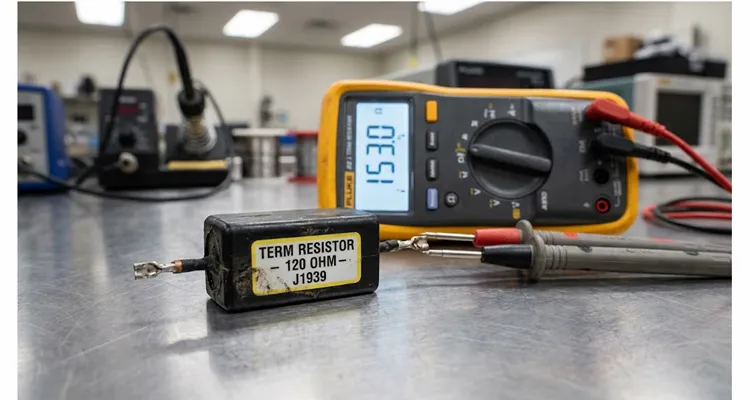
J1939 is a two-wire differential bus with 120-ohm terminators at each end. That part is standard — it is defined in the SAE J1939 top-level document. What matters here is that the bus was not shorted, not open, and not missing a terminator. It was sitting at 153 ohms across pins C and D, and that was enough to kill communication under load. This is the kind of J1939 hot and cold termination resistance shift that a static scan tool test will miss entirely.
The 120-ohm value matches the characteristic impedance of the twisted pair. When the bus transitions between dominant and recessive states, those terminating resistors act as the discharge path for the bus capacitance. If the resistance is off-spec — even by twenty or thirty ohms — the RC time constant shifts. The recessive-state discharge takes longer. The CAN controller’s bit sampling window starts missing edges. Error frames accumulate. The transmit error counter climbs. And when TEC exceeds 255, the node goes bus-off.
That is the part most shops miss. A bus-off condition does not necessarily set a DTC that says “termination resistor bad.” It sets a communication fault that looks like a module failure. So you replace the module. And the fault stays. This is one of the most expensive misdiagnosis patterns in heavy-duty fleets, and it is exactly why we wrote the case study behind the twenty-three cent resistor fleet downtime cost.
Why a Fifteen-Ohm Drift Becomes a Bus-Off Event
The resistor in this truck was a 120-ohm, 1/4-watt axial-lead component, potted in a black epoxy compound inside a molded plastic housing. Externally, it looked perfect. No cracks. No discoloration. No signs of heat damage. But under a stereoscope at twenty times magnification, we found a micro-fissure in the potting compound, roughly three millimeters long, running along the edge where the resistor body met the lead frame. That fissure is a textbook entry point for moisture ingress and pin-to-pin leakage current.
That fissure was the entry point. Over eighteen months of thermal cycling — the kind that happens every time a truck runs from a cold morning start to a hot engine bay and back again — moisture had migrated through the fissure and reached the solder joint between the resistor element and the lead. Galvanic corrosion had set in. The solder joint, once a solid metallurgical bond, was now a resistive interface. The resistance of that joint alone measured in the tens of ohms.
When the truck was cold, the corrosion interface was tight. Resistance was near spec. The bus worked. After two hours of highway driving, as the cab heated up and the potting compound expanded and contracted, the interface loosened. Resistance climbed. The RC time constant shifted. The CAN controller started missing bits. And eventually — not always, but sometimes — the node went bus-off.
The Multimeter Test That Took Four Days to Perform
Here is what the shop should have done on day one. Key off. Batteries disconnected. Multimeter set to ohms. Leads on pin C (CAN_H) and pin D (CAN_L) of the 9-pin diagnostic connector. This is the first step in any serious J1939 physical layer multimeter diagnostic routine.
They measured 153 ohms. Not sixty. Not seventy. One hundred and fifty-three.
That reading told a specific story. In a properly terminated two-resistor network, you would see approximately sixty ohms. If you see around 120 ohms, one terminating resistor is missing or there is an open circuit in the backbone. If you see around forty ohms, someone has installed a third resistor. If you see 153 ohms — well, that is the interesting one. It means both resistors are present, but one of them has drifted upward. The parallel combination of a healthy 120-ohm resistor and a drifted 153-ohm resistor lands almost exactly where they measured. That is why the J1939 hot and cold termination resistance shift is so deceptive.
The technician had been looking at 153 ohms for four days. But he had been looking at it through a diagnostic scan tool that reported “no active faults.” The DTC system could not see it. The voltage test at the diagnostic connector showed 2.5 volts on both CAN_H and CAN_L — normal idle state. The bus was not shorted. It was not open. It was just slightly out of impedance. And that slight drift was enough to kill communication under load.
The Diagnostic Sequence That Should Have Been Followed
Here is the sequence I would have run. It takes about ninety minutes if you have the right tools and you are not guessing. This is a structured J1939 diagnostic workflow built for fleet downtime reduction, not a parts-swapping exercise. If you want the full framework, it is documented in our structured J1939 diagnostic workflow for fleet downtime.
Step 1: Static Resistance Test
Key off, batteries disconnected. DMM across pins C and D at the 9-pin diagnostic connector. Record the value. Sixty ohms plus or minus six is healthy. Anything else starts a diagnostic branch. One hundred twenty ohms means one terminator is missing or there is an open in the backbone. Forty ohms means three terminators. Values above ninety but below one hundred twenty — that is a drifted resistor. That is our 153-ohm case, except that measurement was taken across the parallel combination, so the actual drifted resistor was even further out of spec. For the difference between split termination and standard 120-ohm termination, see our J1939 split termination vs 120-ohm guide.
Step 2: Individual Resistor Isolation
Disconnect each terminating resistor from the bus one at a time and measure it directly. Spec is 110 to 130 ohms. If either resistor measures outside that window, replace it. Do not argue. Do not wait for it to fail completely. The physics of the bus do not care that it “mostly works.”
Step 3: Voltage Verification
Key on, engine off, batteries connected. Measure CAN_H to ground (should be approximately 2.6 volts) and CAN_L to ground (approximately 2.3 volts) at the diagnostic connector. If the voltages are out of range, you have a module loading the bus or a wiring fault. If they are within range but the resistance test failed, you have a termination problem, not a wiring problem.
Step 4: Oscilloscope Inspection
This is where most shops stop, and it is where the real diagnosis begins. Connect a scope probe to CAN_H and another to CAN_L. Set the timebase to capture a full message frame. Look at the differential signal. A healthy bus shows clean transitions, roughly two volts of differential swing, and no significant ringing. A bus with drifted termination shows rounded edges, increased rise and fall times, and often some overshoot on the dominant-to-recessive transition. That overshoot is the bus capacitance discharging through a resistance that is too high. If you are new to scope work on CAN, reading J1939 waveforms like a pro will save you hours. Before you trust what you see on screen, make sure the scope itself is not hiding the problem — a low-bandwidth front end will round off the same edges you are trying to diagnose, which is exactly what our breakdown of why a 50 MHz scope misses CAN bus glitches explains.
Step 5: Wiggle Test with Peak-Hold Ohms
If the static resistance test passes but the fault is intermittent, clip your meter across CAN_H and CAN_L at the diagnostic connector with the meter set to peak-hold ohms. Then physically manipulate the harness — flex the connectors, tug the stub cables, tap on the terminating resistor housings. Watch for any change in the maximum or minimum resistance reading. This catches the cracked solder joint, the loose crimp, the corrosion interface that only opens under vibration. It also catches the slow crimp resistance drift that shows up as J1939 ground offset.
Common Misdiagnosis and the 153-Ohm Paradox
| Diagnostic Step | Expected Healthy Reading | What the Shop Saw | Common Misdiagnosis | Correct Action |
| Static resistance, pins C and D | 55–65 ohms | 153 ohms | “No active faults, bus must be fine” | Isolate and measure each terminator individually |
| Individual resistor measurement | 110–130 ohms | One resistor drifted to 153 ohms | “Resistor is within tolerance” | Replace both terminators as a set |
| Voltage, CAN_H to ground | ~2.6 volts | 2.5 volts | “Voltage is close enough” | Verify resistance first; voltage can look normal with drifted termination |
| Oscilloscope differential signal | Clean transitions, minimal ringing | Rounded edges, overshoot | “Signal looks acceptable on scan tool” | Scope the bus under load; look for RC discharge overshoot |
| Wiggle test with peak-hold ohms | Stable reading | Reading changed under flex | “Intermittent fault, cannot reproduce” | Replace terminator with controlled-cure, vacuum-degassed unit |
A 100-ohm resistor in parallel with a 150-ohm resistor still reads sixty ohms. Never trust a single parallel reading when the fault is intermittent. Always isolate and measure each terminator directly. If you see around forty ohms, that is a different fault — usually a third terminator — and our J1939 double termination and switched terminator diagnosis covers that branch.
The Fix: What We Actually Replaced
The cab-side terminating resistor was the root cause. We replaced it with a unit from our production line — a 120-ohm, 1/4-watt axial resistor potted in a high-temperature epoxy with a controlled cure cycle. The potting compound we use undergoes vacuum degassing before dispensing to eliminate dissolved gases that can form voids during cure. The cure profile runs twenty-four hours at a controlled ramp — not a snap cure, which is where micro-fissures originate. This is the difference between a commodity terminator and a J1939 terminator built to survive fleet downtime.
The resistor element itself is AEC-Q200 qualified, tested to one thousand thermal cycles with resistance drift under one percent.
We also replaced the chassis-side terminating resistor. It tested at 118 ohms — technically within spec, but with a slight upward drift that suggested the same corrosion mechanism was beginning. For a twenty-three-cent part, you replace it while you have the cab apart.
Total parts cost for both resistors: forty-six cents. Total labor for the replacement: about forty-five minutes. Total cost of the four-day misdiagnosis: eleven thousand dollars in fleet downtime, parts, and lost revenue.
Why This Keeps Happening: The Supply Chain Problem Nobody Talks About
The failed resistor in that Kenworth was not a counterfeit part. It was not a cheap aftermarket substitute. It was an OEM-supplied component with a legitimate part number and a legitimate manufacturer. The problem was that the manufacturer’s potting process had a variable — the cure cycle — that was not tightly controlled. Some units came out with a potting compound that was fully cured and hermetic. Others, like the one on that truck, had micro-fissures that only revealed themselves after eighteen months of thermal cycling.
This is the failure mode that certifications alone do not catch. You can have an ISO 9001 certificate. You can have IATF 16949. You can pass PPAP. And still ship a resistor that fails at month nineteen because the potting compound had a void that no visual inspection and no end-of-line electrical test would ever reveal. This is why IATF 16949 cable assembly traceability has to be tied to actual process data, not just a certificate on the wall.
The only defense is process control at the manufacturing level. Vacuum degassing before potting. Controlled cure profiles. In-process monitoring of cure exotherm. And a 100% end-of-line resistance measurement that records the actual value against the serial number of the harness, so that if a field failure occurs, you can trace it back to a specific production batch and a specific cure profile.
That is what we do. Not because it is required. Because we have seen what happens when it is not done.
Fleet Downtime Math: Why a Twenty-Three Cent Part Matters
Let us put the cost in perspective using the actual numbers from this case. Four days of downtime for a Class 8 truck: roughly three thousand dollars at the low end in lost revenue, driver wages, and shipper penalties. Parts thrown at the problem that did not fix it: two thousand dollars. Diagnostic labor, four days of technician time: roughly sixteen hundred dollars at a loaded shop rate. Towing, missed delivery penalties, and the intangible cost of a driver sitting idle: the rest.
Eleven thousand dollars. For a resistor that costs twenty-three cents in production quantities. This is the part of fleet downtime cost that no service manager forgets, and it is why we track cases like the twenty-three cent resistor that caused eleven thousand dollars in fleet downtime.
The economics are brutal because the failure is invisible. The DTC system does not flag it. The voltage test passes. The scan tool says “no active faults.” And so the technician moves on to the next module, and the next, and the next, until someone finally pulls out a multimeter and measures resistance across the bus.
What Good Looks Like: The Four-Step Quality Inspection That Prevents This Failure
Every J1939 harness and every terminating resistor assembly that leaves our factory goes through four inspection stages. These are not generic quality steps. They are direct countermeasures to the micro-fissure failure that killed that Kenworth.
Stage One: Incoming Component Verification
Resistors are sampled from each incoming lot and tested for resistance tolerance at three temperatures — cold soak, ambient, and elevated. We do not trust the manufacturer’s certificate of conformance. We measure. If the resistance drift across temperature exceeds our internal limit, the lot is rejected.
Stage Two: In-Process Potting Verification
After the resistor is potted into its housing, we weigh each unit. A void in the potting compound changes the mass by a measurable amount. If the weight falls outside the control limits, the unit is flagged for X-ray inspection. Voids that would not be visible externally show up clearly on X-ray.
Stage Three: End-of-Line Electrical Test
Every completed J1939 harness assembly is tested with a dedicated J1939 bus simulator. We verify resistance across CAN_H and CAN_L at the diagnostic connector, measure the insertion loss of each stub, and confirm that the completed assembly presents a sixty-ohm differential load to the bus. The test result is recorded and linked to the harness serial number.
Stage Four: Thermal Cycling Audit
From each production batch, we pull samples and run them through accelerated thermal cycling — two hundred cycles from minus forty to plus one hundred twenty-five degrees Celsius. After cycling, we re-measure resistance and inspect the potting compound for micro-cracking. This is the test that catches the failure mode that killed that Kenworth. It is not a quick test. It is not a cheap test. But it is the only way to know whether your potting process is actually producing hermetic seals or just appearing to.
We also run salt spray testing per ASTM B117 for undercarriage and engine-compartment harnesses. A common requirement is ninety-six hours with no red rust. If you operate in coastal or winter-road-salt environments, our salt spray testing for OBD harnesses in coastal fleets explains the test setup and acceptance criteria. We provide PPAP Level 3 files for OEM and Tier 1 customers. The PPAP package includes dimensional results, material certifications, process flow diagrams, PFMEA, control plans, and measurement system analysis. If a supplier cannot produce a PPAP, they are not ready for production-level OEM work. Our PPAP Level 3 documentation for OBD cable assemblies shows what that package actually contains.
How to Audit a J1939 Terminating Resistor Supplier: Seven Questions
Certificates are a starting point. They are not evidence that the process is under control. When you are selecting a supplier for terminating resistor assemblies or heavy-duty J1939 harnesses, ask these seven questions. The answers will tell you more than any catalog page. This audit is the same one we recommend in our seven questions to audit a custom OBD cable supplier and our J1939 harness supplier qualification questions.
Question one: Can you provide the cure profile for your potting compound? A supplier who controls the process will have a documented ramp, soak, and cool-down schedule. A supplier who is buying pre-potted assemblies from a third party will not.
Question two: Do you vacuum-degas the potting compound before dispensing? Dissolved gases form voids during cure. Voids become micro-fissures under thermal cycling. Vacuum degassing is not optional if you want hermetic seals.
Question three: What is your thermal cycling test regimen? Ask for the temperature range, the number of cycles, and the acceptable resistance drift. A credible answer includes specific numbers. A vague answer is a warning.
Question four: Do you perform salt spray testing? For undercarriage and engine-compartment harnesses, salt spray resistance matters. Ask for ASTM B117 test data. A common requirement is ninety-six hours with no red rust. If the supplier cannot provide salt spray data, they are not building for the environments your fleet actually operates in.
Question five: Can you supply a PPAP file? For OEM and Tier 1 customers, a PPAP Level 3 submission is often required. The PPAP package should include dimensional results, material certifications, process flow diagrams, PFMEA, control plans, and measurement system analysis. If the supplier cannot produce a PPAP, they are not ready for production-level OEM work.
Question six: How do you trace a field failure back to a production batch? Ask for the serial number system. Ask how the resistance measurement at end-of-line is recorded. Ask how the cure profile is linked to the batch. Without traceability, a field failure is a mystery. With traceability, it is an engineering problem that can be solved.
Question seven: Can you customize the assembly without changing the process controls? OEM customization often means a different connector, a different length, a different color, or a different AWG. The process controls — vacuum degassing, cure profile, thermal cycling, end-of-line test — must remain identical. If customization means skipping steps, the customization is not worth the risk.
Comparing Termination Faults: What the Resistance Reading Tells You
| Measured Resistance (Pin C to D) | What It Means | Most Likely Cause | Action |
| 55–65 ohms | Healthy bus | Two 120-ohm resistors in parallel, both in spec | No action required |
| ~120 ohms | One terminator missing or open backbone | Failed resistor (open element), broken wire, disconnected connector | Locate and repair the open circuit |
| ~40 ohms | Three terminators on the bus | Extra resistor installed, often during aftermarket upfit | Remove the extra terminator and install a blanking plug |
| 90–110 ohms | Drifted resistor | Corrosion interface or partial element failure in one terminator | Replace both terminators as a set |
| >1,000 ohms | Both terminators missing or open | Backbone disconnected, both resistors failed open, or connector unplugged | Inspect entire backbone for opens |
| 0–2 ohms | CAN_H shorted to CAN_L | Chafed wire insulation, pin misalignment in a connector, internal module short | Isolate the short by disconnecting modules one at a time |
The 153-ohm reading in our case study falls into the “drifted resistor” category. It is the most insidious fault because the bus often works well enough to pass a static test. The communication fault only appears under specific conditions — thermal load, vibration, humidity — which makes it nearly impossible to reproduce in the shop. For a deeper comparison of termination topologies, see the J1939 split termination vs 120-ohm guide and the J1939 double termination and switched terminator diagnosis.
Verifying the Repair: What Success Actually Looks Like
Replacing the resistor is not verification. Verification is a four-part process.
First, measure resistance at the diagnostic connector with the new resistor installed. It should read between 54 and 66 ohms. If it does not, you have another problem.
Second, connect the scan tool and clear all DTCs. Then run the engine under load for at least thirty minutes. Monitor the J1939 data link for error frames. A healthy bus will show zero error frames under normal operating conditions. Any error frames at all indicate a remaining physical layer problem.
Third, connect an oscilloscope and capture a CAN message frame under load. The differential signal should show clean transitions with minimal ringing. If you see significant overshoot on the recessive-to-dominant transition, the bus capacitance is still discharging through too much resistance. If you are deciding whether a scope belongs in your diagnostic kit, our fleet oscilloscope cost-benefit decision is written for exactly that question.
Fourth, wiggle test. With the scope still connected, physically flex the harness and connectors. The waveform should not change. Any visible disturbance indicates a mechanical connection problem that will eventually return as an intermittent fault.
A Note on Connector Pinouts: The 9-Pin Standard
For reference, the SAE J1939 9-pin diagnostic connector uses the following pin assignments, as defined in the SAE J1939/13 off-board diagnostic connector specification:
| Pin | Function | Wire Color | Measurement Pitfall |
| A | Battery negative (ground) | Black | Do not use chassis ground for resistance measurement |
| B | Battery positive (+12V or +24V) | Red | Disconnect batteries before resistance test |
| C | J1939 CAN_H | Yellow | Measure across C and D with batteries disconnected |
| D | J1939 CAN_L | Green | Use dedicated ground stud near diagnostic connector |
| E | J1939 shield (heavy cable only) | Drain wire | Do not confuse shield with ground |
| F | J1587+ (if equipped) | — | Not part of J1939 bus |
| G | J1587- (if equipped) | — | Not part of J1939 bus |
| H | Proprietary OEM use | — | Consult OEM documentation |
| J | Proprietary OEM use | — | Consult OEM documentation |
The terminating resistor measurement is always taken across pins C and D. Do not use the chassis as a ground reference when measuring. Use a dedicated ground stud located as close to the diagnostic connector as possible.
Where the Twenty-Three Cent Number Comes From
I should explain the title. The resistor itself — the component, not the assembly — costs twenty-three cents in production quantities. That is the price of the 120-ohm, 1/4-watt axial-lead resistor with the AEC-Q200 qualification and the thermal cycling test data. This is the same component-level cost we break down in the J1939 terminator twenty-three cent fleet downtime cost analysis.
The assembly — the resistor potted into its housing with the connector and the mounting bracket — costs more. But the component that failed, the resistor element, is a twenty-three-cent part. That is what failed. That is what caused eleven thousand dollars in downtime. The potting compound, the housing, the connector — all of that survived. The twenty-three-cent resistor inside the potting compound was the weak point. If you want the full cost model, the twenty-three cent resistor fleet downtime cost case study walks through every line item.
This is what I mean when I say that in J1939 systems, the physical layer is everything. The protocol is robust. The data link layer is robust. The application layer is robust. But the physical layer is where the electrons actually move, and it is the layer that is most vulnerable to the slow, invisible degradation mechanisms that no DTC will ever flag.
What Fleet Engineers and OEM Procurement Teams Should Take Away
If you are specifying terminating resistors for a J1939 harness, do not treat them as commodity parts. The resistance value is only one specification. The potting process, the cure profile, the thermal cycling performance, and the traceability of the production batch matter just as much.
Ask your supplier for the cure profile. Ask for the thermal cycling test data. Ask for the X-ray inspection results from the potting process. Ask for salt spray data and a PPAP file if you are building for OEM production. If they cannot provide those things, they are not controlling the process. They are hoping for the best.
We have been manufacturing J1939 harnesses and terminating resistor assemblies for over twenty years. Our factory holds ISO 9001, ISO 14001 environmental management, IATF 16949 automotive quality certification, RoHS, CE, UL, and REACH certifications. We operate a 5S-managed production floor with climate-controlled warehousing. We run a four-step quality inspection on every assembly, and we do 100% end-of-line electrical testing with traceability down to the individual harness serial number. The traceability system is described in more detail in our IATF 16949 cable assembly traceability article.
But certifications are a starting point, not a guarantee. IATF 16949 is the baseline for automotive quality. It does not catch a micro-fissure. What catches it is the thermal cycling audit, the X-ray inspection, the vacuum degassing, and the controlled cure profile. That is what we do. Not because it is required. Because we have seen what happens when it is not done.
We also do OEM customization — logo, brand, length, color, AWG — for fleet and equipment manufacturers who need terminating resistors and harness assemblies that meet their specific mechanical and environmental requirements. Every custom build goes through the same inspection protocol. The process controls do not change when the connector or the length changes.
If you are chasing an intermittent J1939 fault, send us the resistance reading at pins C and D, the DTC history, and the harness drawing. If you are specifying a new termination assembly, send the operating temperature range and the connector interface. Our engineering team will review the physical layer and return a diagnostic checklist or a custom termination specification.
FAQ: J1939 Termination and Diagnostic Questions
Q1: My resistance reading at pins C and D is exactly 60 ohms. Can I rule out a termination problem?
Not entirely. A 60-ohm reading confirms that the parallel combination of the two terminators is correct. It does not confirm that each individual resistor is within spec. A 100-ohm resistor in parallel with a 150-ohm resistor gives you 60 ohms. The individual resistors are both out of spec. In our case study, the parallel reading was 153 ohms. That pointed to one terminator that had drifted, not an open circuit. Always isolate and measure each terminator individually if you are chasing an intermittent fault.
Q2: The scan tool shows no active DTCs, but the driver reports intermittent communication faults. What should I check first?
Physical layer. Every time. Static resistance test at pins C and D with the batteries disconnected. Then voltage test with key on, engine off. Then scope the differential signal. Only after you have verified the physical layer should you start looking at modules. In this case, the scan tool reported no active faults for four days while the bus was sitting at 153 ohms.
Q3: How can I tell if a terminating resistor has drifted versus failed completely?
A completely failed resistor reads open — infinite resistance. A drifted resistor reads higher than spec but not infinite. If your parallel reading is in the 90–110 ohm range, one resistor has drifted. If it is around 120 ohms, one resistor has failed open or there is a wiring open. In this case, the drifted resistor measured 153 ohms when isolated.
Q4: Can I just install a new terminating resistor without replacing the harness?
Yes, if the harness connectors are clean and the crimps are sound. But check the connector pins for corrosion and the crimp for mechanical integrity. A new resistor on a corroded connector will fail again. The failed unit in this case had a three-millimeter micro-fissure that allowed moisture to reach the solder joint. The connector pins were clean, but the potting compound was not.
Q5: Why does the fault only appear after the truck has been running for a while?
Because the failure mechanism is temperature-dependent. As the cab heats up, the potting compound expands. If there is a micro-fissure, the expansion opens it further, allowing more moisture ingress or breaking the electrical contact at a corroded solder joint. The resistance changes with temperature. When the truck cools down, the resistance may return closer to spec. That is why the static test in a cold shop can pass while the fault appears only under load. This is the same hot and cold termination resistance shift that we see in field returns.
Q6: What is the difference between a 120-ohm and a 121-ohm terminating resistor?
In practice, very little. Both are within the acceptable tolerance band for a 120-ohm resistor (typically plus or minus five percent for standard parts, plus or minus one percent for precision parts). The CAN physical layer specification calls for 120 ohms nominal, but the actual requirement is that the bus presents a characteristic impedance of approximately 120 ohms. A 121-ohm resistor is fine.
Q7: Can a bad terminating resistor damage an ECU?
Indirectly, yes. A drifted or missing termination causes reflections and signal integrity problems. The CAN controller in the ECU will detect errors and increment its error counters. Over time, repeated error frames and bus-off events can stress the transceiver. But the more common failure mode is that the ECU goes bus-off and stops communicating, which sets a communication DTC that leads technicians to replace the ECU unnecessarily. In this case, the shop replaced the ECM, the instrument cluster, and the ignition switch before measuring resistance across the bus. If you want to avoid that path, our ground offset and ECU replacement avoidance guide is worth reading before you order another module.
Q8: How often should terminating resistors be replaced as preventive maintenance?
They are not typically on a PM schedule. But if you are replacing a harness or doing significant cab work, measure the resistors while you have access. If either resistor measures outside 110–130 ohms, replace it. The cost is negligible compared to the downtime cost of a failure. In this case, the chassis-side resistor measured 118 ohms — technically within spec, but with a slight upward drift. We replaced it while the cab was apart.
Q9: What is the best way to test for an intermittent terminating resistor fault?
Peak-hold ohms on a high-quality DMM. Clip across pins C and D. Wiggle the harness, the connectors, and the resistor housings while watching the display. Any change in the reading indicates a mechanical or thermal interface problem. This test catches the faults that a static measurement misses.
Q10: Does the type of potting compound matter for terminating resistor reliability?
Significantly. The potting compound must be fully cured and free of voids to provide a hermetic seal. Vacuum degassing before dispensing and a controlled cure profile are essential. Snap-cure compounds and compounds with high exotherm during cure are more prone to micro-fissure formation. The failed unit in this case had a micro-fissure that allowed moisture to reach the solder joint. Vacuum degassing and a twenty-four-hour controlled cure are the countermeasures.
Q11: Can I use a 1/2-watt resistor instead of a 1/4-watt to improve reliability?
The power rating is not the limiting factor in a J1939 terminating resistor. The bus operates at very low power — the resistor dissipates milliwatts at most. The failure mechanism is moisture ingress and thermal cycling, not power dissipation. A higher power rating does not help unless the manufacturer has also controlled the potting process and the thermal expansion matching between the resistor body and the potting compound.
Q12: What certifications should I look for in a J1939 harness supplier?
IATF 16949 is the baseline for automotive quality. ISO 9001 is the general quality management standard. For environmental compliance, RoHS and REACH. For product safety in certain applications, UL and CE. But certifications are a starting point, not a guarantee. Ask for process control data — cure profiles, X-ray inspection results, thermal cycling test reports, salt spray data, and PPAP files — that demonstrate the factory is actually controlling the variables that cause field failures. Our J1939 harness supplier qualification questions and seven-question custom OBD cable supplier audit are designed to separate real process control from catalog claims.
If you are chasing a J1939 fault that does not make sense, or if you need terminating resistor assemblies that are built to survive thermal cycling and moisture ingress, reach out to our engineering team. We have seen this failure mode enough times to know exactly what to look for — and exactly how to prevent it in the first place.
WhatsApp: Chat with Linda
Contact Page: Engineering Support
We offer OEM customization on terminating resistor assemblies and J1939 harnesses — logo, brand, length, color, AWG — with full engineering support from prototype through production.
