

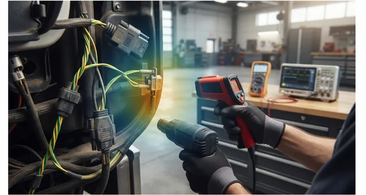
A 2021 Kenworth T680 rolled into a Midwest fleet shop with a CAN bus fault that had already burned five days of diagnostic time. The truck had a PACCAR MX-13, 187,000 miles on the odometer, and a cab-side termination assembly that still looked factory-fresh. The shop had swapped the ECU, the instrument cluster, and the ignition switch — roughly two thousand dollars in parts. None of it fixed the problem. The truck still threw bus-off errors within twenty minutes of every cold start.
When I finally got the call, the first thing I asked was whether anyone had measured the terminating resistors with the cab heat-soaked. Silence on the other end.
That question matters because a J1939 termination resistor (split termination vs 120 ohm guide) can read a perfectly acceptable 120.1 ohms in a 22°C shop and drift to 124.8 ohms after two hours of highway operation in August. That 4.7-ohm shift is enough to alter the RC time constant of the bus, increase the recessive-state discharge time, and push a marginal CAN controller into bus-off (double termination and switched terminator diagnosis). No DTC will ever flag this. The diagnostic connector still shows 60 ohms. The multimeter in your hand is lying to you because you measured the wrong thing at the wrong temperature.
The shop test is a DC resistance check. The failure is an AC timing problem. A 60 Ω reading at 22°C tells you the resistors are connected. It does not tell you what they will do at 90°C.
The 20-to-40-minute failure window: a thermal-drift signature
Why J1939 hot cold resistance drift appears after 20 to 40 minutes
The pattern repeats across trucks, buses, and off-highway machines. The machine starts fine in the morning. Communication is stable for the first twenty to forty minutes. Then, as the engine bay and cab interior reach operating temperature, modules begin dropping off the bus. The transmission ECU goes first, then the aftertreatment controller. Eventually the entire network collapses into bus-off, and the only recovery is a key cycle and a cold soak.
In the T680 case, the technician measured resistance at the diagnostic connector with the ignition off. The reading was 60.2 ohms at 19°C. The wiring harness passed continuity. The terminating resistors looked pristine through their heat-shrink sleeves. There was no corrosion visible at any connector. The DTC set at 83°C coolant temperature, but the problem was declared intermittent and the truck went back into service.
Two weeks later it was back with the same complaint.
What the shop missed is that the resistance measurement was taken at roughly 19°C, while the actual failure occurs at 80°C to 105°C. The terminating resistor itself is a component with a temperature coefficient. If it is a standard thick-film chip resistor, a 100 ppm/°C TCR means a 120-ohm part will shift by approximately 1.0 ohm over an 85°C rise. That alone is survivable. But when the resistor is encapsulated in a potting compound that has absorbed moisture (moisture ingress pin-to-pin leakage current), or when the crimp termination has developed a cold-worked joint (crimp resistance drift 3.2 milliohm J1939 ground offset), the effective series resistance can drift by 15 ohms or more between cold and hot states.
The T680 J1939 termination resistor test readings
I have personally seen a cab-side termination resistor that measured 121.4 ohms at 20°C and 138.6 ohms at 90°C. The owner had replaced three ECUs chasing the fault. The actual culprit was a twenty-two-cent resistor (J1939 terminator 23-cent fleet downtime cost) whose epoxy coating had micro-cracked after eighteen months of thermal cycling. In the T680 case, the hot reading at 91°C was 67.9 ohms at the diagnostic connector after thirty-eight minutes of loaded operation. The cold reading was 60.2 ohms. That 7.7-ohm shift was the whole fault.
What the diagnostic connector sees vs. what the bus experiences
DC resistance check vs. AC termination behavior
The J1939 physical layer (J1939 physical layer multimeter diagnostics) is a differential bus with a characteristic impedance of nominally 120 ohms. The ISO 11898 CAN standard specifies that the physical wires of a CAN network be a single twisted pair with 120 ohms of characteristic impedance, and that both ends of the bus be terminated with resistors equal to that impedance (Texas Instruments: Why Are Termination Networks in CAN Transceivers So Important?). ISO 11898-2 (ISO 11898-2 physical layer) describes the high-speed CAN physical layer that carries the differential signal. When both terminators are present and at nominal value, the parallel combination presents 60 ohms at the diagnostic connector, and the bus behaves as a properly terminated transmission line.
When one resistor drifts high, the termination is no longer matched. The reflection coefficient at that end of the bus increases. Fast edges — and at 250 kbps, the dominant-to-recessive transition is fast enough to launch a reflection down the entire harness (J1939 stub length reflection timing calculation) — begin bouncing between the mismatched terminations. The received differential signal develops ringing and slow settling.
The CAN controller does not care about ringing directly. It cares about whether the differential voltage crosses the recessive threshold before the sample point (J1939 sampling point diagnostics). On a typical high-speed CAN transceiver running at 250 kbps with a sample point near 87.5 percent of the bit time, the recessive edge must settle before that sample instant. If the bus has not fully discharged to the recessive state when the controller samples the bit, it reads a dominant where a recessive should be. That is a bit error. Enough bit errors, and the transmit error counter exceeds 255. The controller enters bus-off.
RC time constant and recessive settling time
The time required for the bus to relax from dominant to recessive is governed by the RC time constant of the network. The R is the parallel termination resistance. The C is the distributed cable capacitance plus the input capacitance of every node on the bus. With 40 pF/m cable capacitance and a thirty-meter backbone, that is roughly 1.2 nF of cable capacitance alone. Add twenty nodes at 10 pF each, and you are looking at 1.4 nF total.
With a proper 60-ohm termination, the time constant is 84 nanoseconds. With a 75-ohm effective termination — what you get when one resistor has drifted from 120 to 180 ohms — the time constant becomes 105 nanoseconds. That is a twenty-five percent increase in settling time. At 250 kbps, a bit is 4 microseconds. The recessive-to-dominant transition must settle well within the bit time. A twenty-five percent increase in settling time eats directly into the timing margin. At room temperature, the margin absorbs it. At elevated temperature, when the resistor drifts further and the controller’s own timing shifts, the margin disappears.
This is why a static DC resistance measurement at the diagnostic connector is nearly useless for predicting intermittent hot-state failures. Many service guides specify 60 ohms ± 6 ohms as the pass criterion. That is a valid acceptance test for a cold, static bus. It tells you the resistors are present and connected. It tells you nothing about what those resistors will do at 90°C. A J1939 datalink resistance test that measures 60 ± 6 ohms at the diagnostic connector with the ignition off is a standard field check, but it is not a thermal stability test (Blue Bird J1939 Troubleshooting Guidelines).
Three mechanisms that make a termination drift hot
Resistor TCR in a 120 ohm terminating resistor
There are three physical mechanisms that cause a J1939 termination resistor to drift with temperature. The first is the inherent TCR of the resistive element. Thin-film and thick-film resistors both have a temperature coefficient, typically in the range of ±50 to ±200 ppm/°C. For a 120-ohm resistor over an 80°C rise, that is 0.5 to 1.9 ohms. Not catastrophic on its own.
Moisture ingress in the J1939 termination resistor
The second mechanism is moisture ingress into the potting compound or conformal coating (IP67 connectors forestry CAN networks). When water vapor penetrates the encapsulation and reaches the resistive element or the termination interface, galvanic corrosion begins. The corrosion products are not pure resistance; they form an ionic conduction path whose resistance is highly temperature-dependent. At room temperature, the corrosion layer may contribute negligible series resistance. At 80°C, ionic mobility increases exponentially, and the effective resistance can rise by ten to thirty percent. In our returned-part logs, moisture ingress is the dominant field failure. Out of forty-seven returned terminations analyzed over the past several years, thirty-one showed moisture ingress, nine showed crimp fractures, and seven showed TCR drift.
Crimp fracture in the J1939 backbone harness
The third mechanism is mechanical. The crimp or solder joint between the resistor lead and the harness conductor can develop a cold-worked zone or a partial fracture. Under thermal expansion, the joint separates slightly, adding contact resistance. The resistance of a partially fractured joint can swing by tens of ohms between cold and hot states. This is particularly insidious because the resistor itself may be perfectly stable — the drift comes from the termination, not the element.
A standard multimeter cannot distinguish between these three mechanisms. It reads total series resistance, whatever the cause. The only way to separate them is to measure the resistor in isolation, at temperature, with a four-wire Kelvin connection. Most shops do not have the equipment or the patience for that. But if you are chasing a thermal-drift fault, the separation matters. Replacing the resistor will not fix a moisture source. Replacing the termination will not fix a transceiver that is drifting common-mode voltage (common-mode voltage J1939 kills communication).
A six-step diagnostic sequence for thermal drift
Tools for a J1939 termination resistor test
The following procedure is what I use when a machine presents with intermittent CAN faults that correlate with operating temperature (J1939 structured diagnostic workflow downtime). It requires a digital multimeter with a minimum resolution of 0.1 ohm, a heat gun, an infrared thermometer, and about ninety minutes of shop time.
Step-by-step J1939 physical layer troubleshooting
- Step 0: Record the thermal baseline. Before you touch the harness, record ambient temperature, coolant temperature, and the surface temperature of the cab-side termination. If the machine is cold, note how long it has been cold-soaked. If it is hot, note how long it has been running. A resistance reading without a temperature reading is not data. It is a guess.
- Step 1: Baseline the bus resistance cold. Park the machine overnight in a space where ambient temperature is below 25°C. With the ignition off and batteries disconnected, measure resistance between CAN+ (Pin C) and CAN− (Pin D) at the diagnostic connector. Record the value to one decimal place. A healthy cold reading is 60.0 to 66.0 ohms. If the reading is already outside this window when cold, you have a static fault and can skip the thermal testing — replace the out-of-spec resistor or repair the open circuit first.
- Step 2: Heat-soak the cab-side termination. Identify the cab-side terminating resistor. On most Class 8 trucks, it is inside the cab harness, often near the bulkhead connector or behind the dash. It is typically a cylindrical connector cap or a molded inline assembly. Use a heat gun on low setting to raise the surface temperature of the resistor body to 85°C to 95°C. Measure with an infrared thermometer; do not guess. Hold the temperature for five minutes, then measure resistance at the diagnostic connector again while the resistor is still hot.
- Step 3: Compare the shift. Subtract the cold reading from the hot reading. A shift of less than 3.0 ohms is normal thermal behavior. A shift of 3.0 to 6.0 ohms is borderline; note it but do not condemn the part yet. A shift greater than 6.0 ohms indicates a thermally unstable termination. The resistor may still pass a cold resistance test, but it will fail in service.
- Step 4: Isolate the resistor from the harness. If the hot shift is excessive, disconnect the cab-side termination from the backbone. Measure the resistor itself, in isolation, at room temperature and then heated to 90°C. If the isolated resistor drifts more than 2.0 ohms over that range, the resistor element or its internal termination is defective. If the isolated resistor is stable but the in-circuit resistance drifts, the problem is in the harness termination — a crimp, a splice, or a connector pin.
- Step 5: Verify the repair under load. After replacing the suspect termination, do not simply measure cold resistance and call it done. Run the machine under load until the cab and engine bay reach operating temperature — typically thirty to forty-five minutes of highway driving or equivalent dyno load. Then measure resistance again. The hot reading should stay within 3.0 ohms of the cold reading. If it does not, you have not found the root cause.
This sequence has caught failures that three different scan tools missed. A static resistance check cannot see a hot drift. A scan tool cannot see a physical layer problem. Only a temperature-controlled resistance measurement will expose it.
Cold-and-hot resistance table from field teardowns
How to read the CAN bus termination hot vs cold table
The table below is compiled from field measurements and forensic teardowns of failed terminations. It is internal field data, not a published specification. Use it as a diagnostic guide, not as a replacement for the OEM service information.
| Condition | Cold Resistance at 20°C | Hot Resistance at 90°C | Delta | Field Sample Size | Likely Root Cause | Recommended Action |
| Healthy termination pair | 60.0–66.0 Ω | 60.0–67.0 Ω | Less than 2.0 Ω | 18 | Normal TCR, stable system | No action |
| One resistor drifting high | 60.0–66.0 Ω | 67.0–72.0 Ω | 3.0–6.0 Ω | 12 | Early TCR drift or minor moisture ingress | Monitor, plan replacement |
| One resistor drifting very high, approaching open | 60.0–66.0 Ω | 73.0–90.0 Ω | 7.0–24.0 Ω | 9 | Severe moisture ingress or internal fracture | Replace immediately; bus-off imminent |
| Moisture ingress in potting | 60.0–66.0 Ω | 80.0–120.0 Ω | 14.0–54.0 Ω | 31 | Cracked potting, unsealed connector | Replace termination; inspect harness jacket |
| Cold crimp or fractured joint | 58.0–68.0 Ω | Erratic, 70–200 Ω | Non-repeatable | 9 | Under-crimped or work-hardened conductor | Replace termination; inspect harness |
A true open circuit on one resistor would not produce 73 to 90 ohms at the diagnostic connector. If one resistor is completely open, the parallel resistance rises toward the value of the remaining resistor, approximately 120 ohms. The 73-to-90-ohm row describes a resistor that has drifted very high — for example, from 120 ohms to 180 or 240 ohms — but has not fully opened. That distinction matters because a technician who expects an open circuit may misread a drifting resistor as a harness fault.
The moisture ingress row is the one that gets missed most often. The cold resistance looks perfect. The hot resistance looks like a missing resistor. The technician replaces the missing resistor with a new one, the problem goes away for three months, and then returns because the moisture source — typically an unsealed connector or a compromised harness jacket — was never addressed.
Five mistakes that keep this fault alive
Mistake 1: Measuring J1939 termination resistance with the ignition on
The J1939 bus is active when the key is on. The CAN transceivers in every ECU present a low impedance to the bus, and the resulting parallel combination will read far lower than 60 ohms. You will chase a short that does not exist. The measurement must be made with the key off and, ideally, the batteries disconnected.
Mistake 2: Using a two-wire ohmmeter for J1939 hot cold resistance
A standard two-wire resistance measurement includes the resistance of the test leads and the probe contact resistance. On a 120-ohm resistor, a 0.5-ohm lead resistance is negligible. But when you are trying to resolve a 2-ohm thermal drift, lead resistance and probe contact variability can mask the very signal you are looking for. Use a four-wire Kelvin measurement or, at minimum, null the lead resistance before every measurement.
Mistake 3: Replacing the J1939 termination resistor without inspecting the termination
The resistor is rarely the root cause. The root cause is the crimp, the splice, the connector pin, or the potting compound that allowed moisture ingress. If you replace the resistor and reuse the same termination, you have reset the clock on the same failure mode. In one fleet case, a technician replaced the same cab-side termination three times in fourteen months because he never replaced the cracked connector seal that was letting water into the assembly.
Mistake 4: Trusting the diagnostic connector for J1939 termination resistance drift
The diagnostic connector is not at the end of the bus. It is a stub, typically fifteen to thirty centimeters from the backbone. A resistance measurement at the diagnostic connector includes the stub’s contribution, which is usually small but can become significant if the stub has a poor splice. The only definitive measurement is at the termination itself, with the termination isolated from the backbone.
Mistake 5: Declaring success after a cold J1939 termination resistor test
The acceptance criterion for a J1939 termination repair is not 60 ohms cold. It is stable resistance across the operating temperature range. If you have not measured hot, you have not verified the repair. A cold-only check is the single most common reason this fault returns.
How to confirm the fix is real
Cold resistance check for J1939 termination resistance drift
A repaired termination must pass several checks before the machine leaves the shop. These are the same checks we apply on the factory floor before any J1939 backbone harness ships to an OEM.
Check 1: Cold resistance. With the machine cold-soaked overnight, measure the parallel termination resistance at the diagnostic connector. It must fall between 60.0 and 66.0 ohms.
Hot resistance check for CAN bus termination thermal drift
Check 2: Hot resistance. Run the machine until the cab-side termination reaches 85°C to 95°C surface temperature. Measure again. The reading must remain within 3.0 ohms of the cold value.
Differential voltage and recessive settling time
Check 3: Differential voltage swing. With the ignition on and the bus active, measure the differential voltage between CAN+ and CAN− with an oscilloscope or a differential probe (reading J1939 waveforms like a pro). A healthy bus swings between approximately 2.0 volts and 3.0 volts peak-to-peak for the dominant state and returns to near 0 volts for the recessive state. Ringing on the recessive edge should settle within 200 nanoseconds. If the recessive edge is still ringing when the next bit begins, the termination is still mismatched. A 50 MHz scope can miss these fast glitches entirely (why 50 MHz scope misses CAN bus glitches).
Error counter and bus-off behavior
Check 4: Error counter behavior. Connect a CAN analyzer or a scan tool that reports CAN error counters. Run the machine under load for at least thirty minutes. The transmit error counter and receive error counter should remain at zero or at their baseline values. Any upward trend in either counter indicates that the physical layer is still marginal.
Common-mode voltage check
Check 5: Common-mode voltage. Measure the common-mode voltage of CAN+ and CAN− relative to ground while the bus is active and hot (J1939 common-mode voltage shift measurement oscilloscope guide). A healthy J1939 bus sits at approximately 2.5 volts common mode. If the common-mode voltage at one node drifts by more than 0.5 volts as the ECU heats up, that node’s transceiver is suspect.
Thermal soak and data log
Check 6: Thermal soak and data log. For critical machines, run a forty-eight-hour thermal soak with a CAN analyzer logging error counters and bus load. The log should show no bus-off events, no increasing error counters, and no unexplained drops in bus load. An eye diagram captured at the end of the soak gives you a visual record of the recessive-edge settling.
Only when all applicable checks pass can the repair be considered complete.
What our PPAP and salt spray testing data actually check
Potting compound cure and J1939 termination reliability
I work for a factory that has been building J1939 backbone harness and diagnostic cables for twenty-one years. We are a direct factory, not a trading company. We ship to OEMs and tier-one suppliers. When we receive a complaint about a J1939 termination resistor that drifted in the field, the first thing we do is pull the production record for that lot and run a failure analysis on the returned part (IATF 16949 cable assembly traceability).
What we have learned from hundreds of teardowns is that the vast majority of field failures trace back to three manufacturing variables: the potting compound cure cycle, the crimp force and tooling, and the moisture barrier integrity.
A properly cured potting compound has a glass transition temperature well above the maximum operating temperature of the harness. If the cure cycle is abbreviated — for example, to meet a shipment deadline — the compound never fully cross-links. It remains slightly thermoplastic. At 90°C, it softens. The resistor element inside can shift microscopically, the termination interface can open, and the resistance drifts. We use vacuum degassing before potting and a verified cure profile with thermocouple monitoring on every batch. It adds cost. It eliminates an entire failure mode.
Crimp force and J1939 backbone harness quality
The crimp is equally critical. A properly crimped termination has a defined compression ratio, verified by pull-test and cross-section on a sampling basis. An under-crimped termination has a higher contact resistance that is stable at room temperature but becomes unstable under thermal cycling. An over-crimped termination work-hardens the conductor and can fracture under vibration. We use calibrated crimp tooling with automatic force monitoring on every cycle, and we cross-section a sample from every production shift. Our four-step quality inspection covers incoming material, in-process crimp and assembly, 100 percent tested resistance and insulation testing (continuity 500VDC IR testing CAN bus failures), and final QA audit before packing.
Salt spray testing and PPAP documentation
Moisture barrier integrity is verified by IP67 immersion testing and, for critical applications, by salt spray testing per ASTM B117. We run ninety-six-hour salt spray testing on representative samples from every production lot destined for underhood or exposed-chassis applications. The test is not fast and not cheap. It is the only way to know that a harness will survive five years of road spray and thermal cycling. We also supply PPAP documentation for OEM customers, including dimensional reports, material certifications, process flow diagrams, PFMEA, and control plans. PPAP Level 3 is available on request. The PPAP package is not a marketing document. It is the evidence trail that lets an OEM trace a field failure back to a specific production parameter and correct it. Without that traceability, every field failure becomes a guessing game.
We hold ISO 9001, ISO 14001 (ISO 14001 certification), and IATF16949 (IATF 16949 certification milestone) certifications. Products can be supplied to RoHS, CE, UL, and REACH requirements where applicable. Our production floor runs 5S management with climate-controlled warehousing for moisture-sensitive components. Our termination assemblies use full-plastic design where specified, and every assembly is 100 percent tested for resistance and insulation integrity before it ships. OEM customization is available for logo, brand marking, cable length, jacket color, and conductor AWG.
When the resistor is not the problem
Common-mode voltage drift that mimics termination drift
There is a scenario I have seen three times in the past two years that deserves its own discussion because it breaks the standard diagnostic logic. The machine presents with classic thermal-drift symptoms: cold start is fine, hot operation fails. The technician measures the termination resistors, finds one that drifts excessively, replaces it, and the problem persists.
In each of those three cases, the actual root cause was a common-mode voltage shift on the bus caused by a failing ECU transceiver. As the transceiver heated up, its output common-mode voltage drifted outside the acceptable range. The differential signal was still present, but the CAN receivers in the other nodes could no longer resolve it correctly. The termination resistor was a red herring — it did drift slightly, but not enough to cause the failure. The real culprit was the transceiver.
The diagnostic for this condition requires a differential oscilloscope with a common-mode measurement capability. You need to measure not just the differential voltage between CAN+ and CAN−, but also the common-mode voltage of both lines relative to ground. A healthy J1939 bus sits at approximately 2.5 volts common mode. If the common-mode voltage at one node drifts by more than 0.5 volts as the ECU heats up, that node’s transceiver is suspect.
This is why I always tell technicians: measure the resistor, but do not stop there. The resistor is the easiest component to test and the most likely to be replaced. It is not always the cause.
Related products and OEM support
If you are an OEM engineer, fleet maintenance manager, or procurement specialist dealing with J1939 physical layer problems, we build the components that go into the backbone. Our J1939 termination assemblies are available with 120-ohm resistors in molded, potted, and field-serviceable configurations. We offer OEM customization on logo, brand marking, cable length, jacket color, and conductor AWG. Every assembly is 100 percent tested for resistance and insulation integrity before it ships.
We hold ISO 9001, ISO 14001, and IATF16949 certifications. Our production floor runs 5S management with climate-controlled warehousing for moisture-sensitive components. We provide salt spray testing and PPAP documentation on request. If you need a termination resistor that holds its value from minus forty to plus one hundred twenty-five degrees Celsius, we can build it and we can prove that it holds.
For engineering support or to discuss a specific failure mode, send us your cold and hot resistance readings, bus length, node count, termination part number, and a scope capture if you have one. Our engineering team will return a failure-mode matrix and, if needed, a custom termination sample plan. We are not a catalog distributor. We are a factory, and we answer technical questions with data, not sales copy.
Contact: https://obd-cable.com/contact/
FAQ: J1939 termination resistance drift
What causes a 4.7 Ω hot/cold shift in a J1939 termination?
A 4.7 Ω shift usually comes from a combination of resistor temperature coefficient, moisture ingress in the potting compound, and termination interface instability. A standard 120-ohm resistor with a 100 ppm/°C TCR shifts about 1.0 ohm over an 85°C rise. The remaining 3.7 ohms comes from the termination, not the resistor element. That is why replacing only the resistor often fails to fix the fault.
Can a terminating resistor pass a cold acceptance check and still fail hot?
Yes. SAE J1939-11 specifies a nominal 120-ohm termination at each end of the backbone. A resistor that measures near nominal at 25°C can drift high at 90°C if it has a moisture ingress problem or a marginal TCR. The cold acceptance check confirms the resistor is present and connected. It does not confirm thermal stability.
How much resistance drift is normal over temperature?
For a healthy termination with a standard TCR, expect 1.0 to 2.0 ohms of drift over an 80°C rise. If you measure more than 3.0 ohms of shift between cold and hot states, the termination deserves investigation. More than 6.0 ohms of shift is a failure waiting to happen.
Why does the diagnostic connector still read 60 ohms when the bus is failing?
The diagnostic connector measures the parallel combination of both termination resistors. If one resistor drifts from 120 to 150 ohms, the parallel combination changes from 60.0 to 66.7 ohms. That is still within many published acceptance windows. The DC measurement does not capture the AC impedance mismatch that is causing the communication fault.
How does 250 kbps versus 500 kbps change termination drift sensitivity?
At 500 kbps, the bit time is 2 microseconds instead of 4 microseconds. The recessive settling time must fit into a shorter window. A termination drift that is marginal at 250 kbps can become a hard failure at 500 kbps. If you are troubleshooting a 500 kbps J1939 network, measure hot and cold resistance with tighter tolerances and verify the recessive edge with an oscilloscope.
Can a star topology mimic termination drift?
Yes. A star topology creates multiple stubs and impedance discontinuities that produce reflections similar to a mismatched termination. The cold resistance may still read 60 ohms, but the hot bus behavior can look like termination drift. If the harness has a star configuration, document the topology before condemning the termination resistors.
Does the engine-side or cab-side termination fail more often?
In our failure analysis logs, cab-side terminations fail more frequently than engine-side terminations. The cab environment experiences wider temperature swings — from ambient cold starts to high solar load — and the cab harness often has more flex points and connector interfaces. Engine-side terminations are usually better protected from moisture but are exposed to higher steady-state temperatures.
What role does the potting compound play in termination reliability?
The potting compound serves three functions: it mechanically stabilizes the resistor element, it provides a moisture barrier, and it acts as a thermal conductor to distribute heat away from the resistor. A poorly cured or moisture-permeated potting compound fails at all three. We verify cure cycles with thermocouple monitoring and test moisture barrier integrity with salt spray testing per ASTM B117.
Can a termination resistor be repaired in the field, or must it be replaced?
A termination resistor that has drifted thermally cannot be repaired. The drift is a bulk material property or an interface degradation that cannot be reversed. Replace the assembly. If the drift is caused by a cold crimp, the termination can sometimes be re-crimped with proper tooling, but the conductor may already be work-hardened. Replacement is the reliable option.
How does the CAN controller error counter behave when termination drifts?
As the termination drifts and the recessive settling time increases, the controller begins to detect bit errors. The transmit error counter increments with each error. When the transmit error counter exceeds 255, the controller enters bus-off. The recovery requires 128 occurrences of 11 consecutive recessive bits — which is exactly the condition that the drifted termination makes difficult to achieve.
What is the relationship between termination drift and bus length?
Longer buses have higher total capacitance. The RC time constant is proportional to both resistance and capacitance. A bus that is marginal at thirty meters with a drifted termination may be completely non-functional at forty meters. If you are extending a backbone, you must verify termination stability more rigorously.
Do you offer termination assemblies with extended temperature range?
Yes. Our standard terminations are rated for minus forty to plus one hundred twenty-five degrees Celsius. We can provide assemblies with tighter TCR specifications for applications where thermal drift is a known concern. PPAP documentation and salt spray testing reports are available for OEM qualification.
