

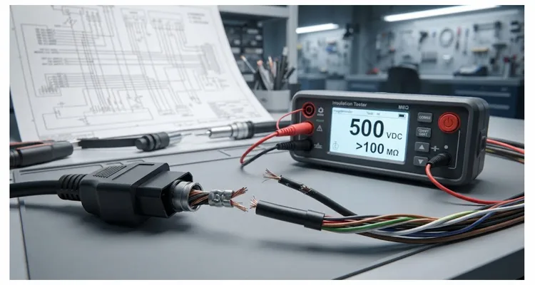
On a production test bench running a 2019+ J2534 flash routine, the sequence fails at block 7 of 12. The error log shows a timeout on Tester Present. You check the driver, swap the USB port, reinstall the firmware. Nothing changes. Then you press the OBD connector sideways and the counter resets.
The problem was never in the software stack—it was a two-ohm intermittent open in the CAN High line, caused by a crimp micro-fracture that passed visual inspection six months earlier. I have pulled apart enough failed harnesses to recognize this signature: the copper strands look intact, but under a microscope you see a hairline crack at the crimp shoulder.
If you have spent any time diagnosing vehicle communication faults, you have seen this pattern. The cable is not completely broken. It is intermittently broken or partially leaking current. It is noisy enough to corrupt high-speed CAN or FlexRay signals, but not dead enough to be detected by a simple “does it power on” test.
On our production line, sampling is not an option. Every single cable passes through two non-negotiable tests before it ships: 100% Continuity Testing and 500VDC Insulation Resistance (IR) Testing.
The Physics of Failure: Where Cheap Cables Go Wrong
To understand why we test this way, you need to understand the failure modes at the copper level. A diagnostic cable is not just a passive conductor; it is a system of conductors, insulators, and connectors.
Failure Mode 1: The Micro-Fracture (Continuity)
When wire is stripped, crimped, and terminated, it is subjected to mechanical stress. If the stripping blade is slightly dull or the tension is off, you create a nick in the copper strands. During assembly, the cable passes a simple “beep” continuity test. But six months later, on a vibrating engine dyno, that nick becomes a stress riser. The remaining strands fatigue and snap. You now have an intermittent connection that passes DC voltage sometimes, but fails under the high-frequency load of modern vehicle networks.
A micro-fracture typically adds between one hundred milliohms and five ohms of unstable resistance. That is enough to distort the differential voltage on CAN High and CAN Low, causing the transceiver to misinterpret recessive and dominant bits. The result is a flood of error frames and, eventually, a Bus Off state.
This failure signature is closely related to what we document in our analysis of crimp resistance drift and ground offset, where the smallest mechanical defect in a terminal crimp creates a measurable electrical instability under vibration and thermal cycling.
Failure Mode 2: The Invisible Path (Insulation Resistance)
PVC and TPE jackets are insulators, but they are not perfect. If the plastic is contaminated during extrusion, or if the mold temperature is wrong during overmolding, you can create carbon tracking or moisture traps. A standard multimeter set to continuity or resistance will not flag this. However, if you apply five hundred volts DC across the pins, you might find that the insulation is allowing a micro-leakage current of a few microamps.
Why does this matter? In a twelve-volt or twenty-four-volt system, five hundred volts seems like overkill. But vehicle networks are not steady state. Inductive loads such as solenoids and injectors can generate back-EMF spikes. If your cable insulation is weak, these spikes create crosstalk between the CAN High and CAN Low lines, degrading signal integrity and causing dropped frames.
We have covered this exact failure path in a dedicated article on moisture ingress and pin-to-pin leakage current, where a small amount of absorbed moisture inside the connector body can create a leakage path that only appears above fifty volts.
Engineering the Solution: The 4-Step Verification Process
For cables shipped to Tier 1 test system integrators, a single field failure can trigger an 8D report and a containment audit. We run these tests because the cost of a missed micro-fracture is a line-down situation at the customer’s site.
Here is how we build that reliability into the physical product.
Step 1: Crimp Force Management
Reliability starts before the plastic is even molded. We do not use soldered connections for high-flex applications. Solder wicks up the strands and creates a rigid point that cracks. We use precision crimping tools with force monitoring. If the crimp height is off by a micron, the tool alarms. This ensures the copper structure remains intact, eliminating the micro-fracture scenario described earlier.
Step 2: The 100% Continuity Test (The Current Path)
After the connectors are terminated, every single cable is placed on a custom test fixture. This is not a multimeter check; it is a bed-of-nails test jig connected to a high-precision milliohm meter.
What we measure: We are not just looking for a short or an open. We measure the end-to-end resistance of every single pin. The tolerance is tight. If a specific length of AWG 22 copper should measure eighty-five milliohms, we set a pass/fail window of plus or minus five percent. If the resistance is too high, we know there is a partial break or a poor crimp. If it is too low, we know there might be a stray strand shorting to an adjacent pin. This ensures that the wire gauge and the crimp integrity are perfect, not just “connected.”
For engineers building test bench OBD cables, the relationship between AWG, loop resistance, and ground separation is critical, and our continuity test validates that every single conductor meets the expected resistance for its length and gauge.
Step 3: The 500VDC Insulation Resistance (IR) Test (The Dielectric)
This is the test that separates professional harnesses from hobby-grade cables. We apply five hundred volts DC between:
- Every pin and every other pin (pin-to-pin)
- Every pin and the outer shield or drain wire (if applicable)
- Every pin and the outer jacket surface
We use a megohmmeter to measure the resistance. The requirement for a pass is greater than one hundred megaohms. If a cable has compromised insulation—micro-tears, moisture, contaminated resin—the megohmmeter will catch it instantly. This guarantees that there is no ghost capacitance or leakage path that could corrupt high-speed data signals.
This is specifically relevant for cables used in EV diagnostics, where isolation between high-voltage battery systems and low-voltage communication lines is a matter of safety. A leakage path of a few microamps at five hundred volts can become a safety hazard when the cable is routed near a four-hundred-volt bus bar.
Step 4: Visual and Mechanical Verification
Finally, we inspect the overmolding. This is a critical structural point. Under our 5S management system, we maintain a climate-controlled warehouse. Why? Because temperature and humidity affect plastic shrinkage. If the strain relief is molded too cold, it will crack. We inspect for flash, sink marks, and contamination before the unit is bagged and sealed.
Common Mistakes in the Industry (And How to Spot Them)
I often get samples from other suppliers sent to our lab for reverse engineering or failure analysis. Here is what I see that kills cables in the field.
The table below summarizes the three most common mistakes and how to identify them.
| Mistake | What the Supplier Claims | What Actually Happens | How to Detect It |
| Loop Test Lie | “100% tested” | Only checks continuity with a 5VDC LED fixture; cannot measure resistance or leakage | Ask for milliohm and megohm test data |
| Offshore Cable Trap | “High-quality raw wire” | Uses wire from uncertified traders with poor extrusion; crimp is good but copper is bad | Request material certifications; perform bend test |
| Ignoring Dwell Time | “500V IR test performed” | Applies voltage for 0.1 seconds; misses dielectric absorption faults | Require test report showing dwell time and actual megohm reading |
1. The “Loop” Test Lie
Many factories claim “100% tested.” What they mean is they plugged the cable into a board with an LED. A typical loop fixture applies five volts DC through a one-kilohm resistor and checks for a logic high. It cannot distinguish a fifty-milliohm connector from a five-ohm one, and it certainly will not catch a two-hundred-microamp leakage path between CAN High and chassis ground. This misses most potential failures.
2. The “Offshore” Cable Trap
Even if the assembly factory is good, they might be buying raw wire from a trader who does not maintain proper extrusion temperatures. You can crimp bad wire perfectly, and it will still fail. We control the source. As a factory with over twenty years of manufacturing experience, we extrude our own wire or source strictly from audited mills to ensure RoHS, CE, and REACH compliance.
3. Ignoring the “Dwell” Time
You cannot run a five-hundred-volt IR test for one-tenth of a second and expect accurate results. Dielectric absorption requires time. We hold the voltage for a specific dwell time—typically one second to sixty seconds depending on the cable complexity—to allow the dielectric to stabilize. A quick pulse test can easily miss a high-resistance fault that breaks down under sustained load.
How to Verify Insulation Resistance on Incoming Cables (Without a Lab)
If you are an engineer dealing with intermittent field failures, you need to implement a burn-in or verification protocol. When you receive cables from us or any supplier, do not just plug them into the car. Do a bench test first.
Follow these three checks:
- Check the shield. Use a meter to verify continuity between the connector shell and the shield pin. If this is open, EMI will corrupt your data.
- Shake test. Set your meter to continuity, plug the cable in, and aggressively whip the cable near the strain relief. If the beep drops out, the crimp is failing. We have formalized this bench check into a repeatable wiggle test protocol for J1939 harness opens, which applies the same principle to heavy-duty diagnostic harnesses.
- Ask for the data. If you are buying for a production line, ask your supplier for the test report. We supply statistical process control (SPC) data with our batches, showing the measured insulation resistance values for that lot. If a supplier cannot produce this data, they are not testing.
Reliability is a Manufacturing Culture
Under IATF16949 clause 8.6.2, we are required to document control plans for each cable assembly. Our control plan for OBD-II cables specifies the five-hundred-volt IR test as a mandatory in-process check, with the actual megohm reading recorded on the traveler for every unit—not just a pass/fail stamp. You can read more about our journey to IATF 16949 certification and what it means for our production controls.
Beyond quality management, our environmental controls are audited under ISO 14001, which ensures that the materials we use—from PVC jackets to copper conductors—are handled and sourced with full traceability and minimal environmental impact.
A recent OEM customization project illustrates how this works in practice. A customer needed a six-meter cable for a chassis dyno cell where the operator had to route the harness through a cable track. We changed from twenty-two AWG to twenty AWG for CAN lines to keep voltage drop below fifty millivolts at full length, and used a high-flex TPE jacket rated for ten million bending cycles. The customer’s previous supplier had used standard PVC, which cracked after three months. We handled the engineering support from schematic review to mass production, including custom pin mapping and jacket color to match the tester’s branding.
Do You Need Engineering Support?
If you are working on a new tester platform and need to validate a wiring harness under real load conditions, our engineering team can review your schematic and suggest pin assignments, shielding strategies, and test parameters.
Do not send a generic inquiry if you have a technical drawing. Use our WhatsApp channel or the Contact Page to speak directly with our engineering team. We can walk you through material selection, pin-out mapping, and mechanical constraints for your specific application. We typically respond with a technical reply within one business day.
WhatsApp: Chat with Linda on WhatsApp
Contact Page: Get in Touch for OEM Customization
FAQ: Technical Questions on Diagnostic Cable Testing
1. Why test at 500VDC instead of 250V or 1000V?
Five hundred volts DC is the industry standard for testing low-voltage cable assemblies to ensure they can withstand transient spikes and eliminate leakage paths without causing stress to thin-wall insulation. Testing at one thousand volts can actually damage the insulation of cables designed for low-voltage data protocols, creating a failure where none existed.
2. Does 100% testing mean every cable or a batch sample?
We literally test every single cable on a fixture. Statistical sampling is for process control, not for selling a safety-critical component. The four-step quality inspection includes final functional testing on one hundred percent of units.
3. Can a cable pass continuity but fail the insulation resistance test?
Yes, and it is very common. The copper wire might be perfectly connected, but if the plastic overmold has a microscopic void or a carbon particle, current can leak between adjacent pins under high frequency or voltage. The IR test catches what a multimeter cannot.
4. What is the minimum acceptable insulation resistance value?
For automotive diagnostic applications, we hold a strict standard of greater than one hundred megaohms at five hundred volts DC. Values below this suggest moisture ingress or material degradation that will likely worsen over time.
5. How does insulation resistance affect CAN bus signal quality?
A low IR value creates a parasitic resistance path between the CAN High and CAN Low wires. This distorts the differential voltage signal, leading to bit errors, increased error frames, and eventual Bus Off states.
6. Does cable length affect the test results?
Yes. Longer cables have more surface area for leakage and higher capacitance. Our test fixtures are calibrated for the specific length and AWG of the cable being produced to ensure the readings are accurate and relevant to the application.
7. Are your cables compliant with environmental standards?
Yes, our raw materials comply with RoHS, REACH, and CE requirements. We specifically avoid harmful phthalates in the PVC jackets, which can degrade over time and cause brittleness.
8. How do you handle custom OEM requests regarding pinouts and lengths?
We work from your drawings or a sample. We can alter the pinout, change the wire gauge to handle higher current loads such as EV battery management systems, and adjust the jacket color and branding. Engineering support is the core of our service.
9. What is the difference between a “tested” cable and a “tested + certified” cable?
A tested cable passes a function check. A certified cable comes with documentation proving the resistance and IR values. For OEMs subject to audits under IATF16949, this documentation is a requirement for your supply chain.
10. Do you provide cables for high-voltage EV diagnostic ports?
Yes. We manufacture specific harnesses for EV applications that require higher dielectric strength. While the communication pins still require the five-hundred-volt test, we can custom-build assemblies with reinforced insulation for proximity to high-voltage bus bars.
