

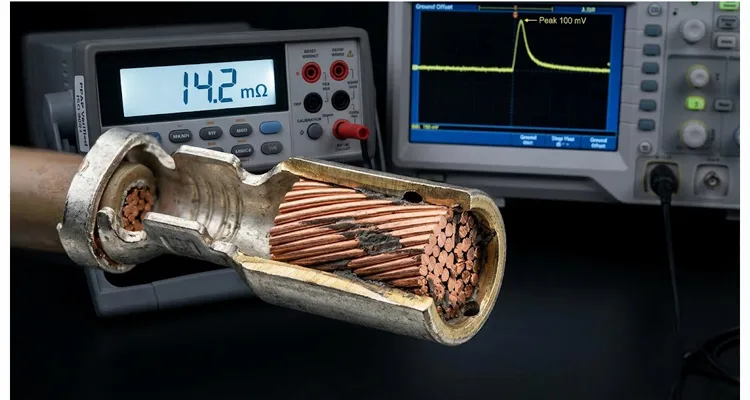
The first sign of trouble was a crimp height report that looked perfect. It was December 2023, and a harness line in Suzhou was shipping engine ground cables for a 1.5L turbo program. Every measurement sat dead center: 1.42 mm crimp height, 92 N pull force, 0.82 mΩ four-wire resistance on a 0.75 mm² copper conductor. Twelve months later, three of those cables came back with P0341 codes and a scope trace showing 100 mV of ground bounce between the ECU ground pin and chassis ground under load.
The root cause was not a broken wire. Not a loose bolt. It was a crimp resistance drift that started as a 0.5% change on a lab report.
The numbers below come from a terminal teardown I did on those returned harnesses. They show exactly how a 0.5% drift turns into a 100 mV ground offset. If you deal with engine harnesses, body grounds, or any high-vibration connector system, the pattern should look familiar.
The field pattern: one connector, twelve months, and a moving ground reference
The vehicle was a 1.5L turbocharged platform. The suspect ground circuit carried sensor return currents from the camshaft position sensor, the oil pressure switch, and a low-side driver for the VVT solenoid. Total continuous current through the ground eyelet was around 1.8 A, with transient pulses up to 6 A during solenoid actuation.
Initial production data for the terminal crimp:
| Parameter | Initial measurement |
| Crimp resistance (four-wire) | 0.82 mΩ average (n=30) |
| Crimp height | 1.42 mm ±0.02 mm |
| Pull force | 92 N average |
| Visual inspection | No cracks, no loose strands |
After 12 months in the field, three returned harnesses were cut open and measured again. The average crimp resistance had moved to 1.84 mΩ. Two of the ten terminals measured above 5 mΩ, and one read 14.2 mΩ. On that one terminal, the ground offset at 1.8 A was 25.6 mV. But the scope trace showed the full 100 mV offset only when the VVT solenoid fired, pulling 6 A through the same ground path. At 6 A, 14.2 mΩ produces 85.2 mV. Add the resistance of the eyelet-to-chassis bolt interface and the wire barrel, and the total offset crossed 100 mV.
The ECU interpreted that moving ground reference as a sensor signal shift. The camshaft sensor is a Hall-effect device with a 0–5 V output. A 100 mV shift on its ground pin changes the threshold crossing point. The engine ran rough, threw intermittent P0340/P0341 codes, and occasionally stalled when the VVT solenoid engaged.
The initial 0.5% resistance increase was not the cause of the 100 mV offset. It was the first measurable sign of a degradation process that would become non-linear.
Why a 0.5% resistance increase is not a rounding error
A 0.5% increase on a 0.82 mΩ crimp is 0.0041 mΩ. That is below the resolution of most handheld milliohm meters. But in a connector that lives in an engine compartment, that tiny number means something physical has already changed inside the crimp.
Micro-motion starts a fretting cycle
Engine vibration causes relative movement between the wire strands and the terminal barrel. The movement is tiny—often less than 5 µm. But it is enough to break the metallic junctions that form during crimping. Each time a junction breaks, fresh tin or copper is exposed. The exposed surface oxidizes almost immediately in engine compartment air. When the vibration cycle repeats, the oxide layer thickens.
A good crimp isn’t just tight—it’s a cold weld across most of the strand bundle. But that weld isn’t permanent. Engine vibration works on it like a file, breaking a few junctions every cycle. What’s left is a patchwork: some spots still metal-to-metal, others bridged by oxide. The current doesn’t spread evenly anymore. It funnels through the good spots, heats them, and makes the oxide grow faster. That’s why the first 0.5% increase looks harmless on a milliohm meter but is actually the start of a curve that steepens every week.
Contact area shrinks, current density climbs
For a 0.75 mm² conductor, a good crimp will have 70–85% of the strand area in intimate contact with the barrel. That means the effective contact area is roughly 0.55–0.64 mm².
When fretting begins, the contact area does not decrease uniformly. Individual strand-to-barrel junctions break at random locations. The remaining junctions carry the same total current, so local current density rises. At a 6 A pulse, the current density in a healthy crimp is about 10 A/mm². In a degraded crimp with only 20% of the original contact area remaining, local current density can exceed 40 A/mm². At that level, localized heating causes thermal expansion mismatch between the copper strands and the tin plating. The expansion creates more micro-movement, which accelerates fretting.
Salt spray turns a small void into an electrochemical cell
This specific vehicle operated in coastal regions where road salt is used six months of the year. The terminal was a tin-plated brass barrel with a copper alloy core. The wire was unplated copper, as specified. Tin and copper are not far apart on the galvanic series, but they are far enough. In the presence of a salt electrolyte, a galvanic couple forms. The tin plating acts as a sacrificial anode in some localized areas, while the copper strands become cathodic.
The result is pitting corrosion at the edge of the crimp where the wire enters the barrel. Salt spray testing later reproduced the same failure mode: after 96 hours of salt spray per ASTM B117, terminals with 0.5% initial drift showed visible white corrosion products at the barrel mouth. The corrosion products were tin oxide and tin chloride. They increased the crimp resistance further and created a barrier that trapped moisture inside the barrel.
Step-by-step diagnosis: how to find the drifting crimp before it reaches 100 mV
If you are seeing intermittent sensor faults, ground offset issues, or unexplained ECU resets, follow this sequence before you blame the sensor or the ECU.
Step 1: Map the ground tree under actual load
Do not measure resistance with the circuit unpowered. Use a current clamp and a multimeter with a fast min/max function. Record the voltage drop between the ECU ground pin and the chassis ground stud while the engine runs and while the suspect actuators cycle. Note the peak voltage drop. If the peak exceeds 50 mV, you have a ground integrity problem. Write down the current at that peak so you can calculate the resistance. If you are chasing a ground offset that comes and goes, this guide to measuring J1939 ground offset voltage walks through the same measurement sequence on a vehicle network.
Step 2: Measure crimp resistance with a four-wire setup
Disconnect the circuit. Cut the wire 20 mm from the terminal. Use a micro-ohmmeter with Kelvin probes. Clamp one probe pair on the wire conductor 10 mm from the crimp barrel. Clamp the other pair on the terminal body as close to the barrel as possible. Record the resistance. Repeat on at least 10 samples from the same production lot. Compare the average to the original PPAP crimp height capability data. If the average has increased by more than 0.5%, treat the lot as suspect. For a deeper look at how we measure loop resistance and ground separation on a test bench, see our teardown of OBD cable AWG resistance and ground separation.
Step 3: Section the terminal and inspect strand compaction
Cut the terminal longitudinally through the center of the barrel using a low-speed saw with coolant. Polish the cross-section. Under a microscope at 50x magnification, check for these indicators:
- Voids between strands larger than 10% of strand diameter
- Cracks in the terminal barrel at the base of the crimp wings
- Separation between the wire strands and the barrel wall
- Presence of dark oxide layers at the strand-to-strand interfaces
If you see any of these in a terminal that passed initial pull force testing, the crimp height was likely set too low or the crimp tooling was worn.
Step 4: Run an accelerated drift test
Take 10 terminals from the suspect lot and 10 from a known-good lot. Mount them on a fixture that simulates the vibration profile of the engine compartment. A random vibration profile from 10 Hz to 2000 Hz with a PSD of 0.02 g²/Hz applied for 8 hours per axis is a good starting point. Cycle the temperature between -40°C and 125°C with a 30-minute dwell at each extreme. Repeat the temperature-vibration combined test for 100 cycles. After the test, measure crimp resistance again using the four-wire method.
Step 5: Calculate drift rate and compare to field data
If the resistance increase after the accelerated test is more than 1% from the initial value, the terminal will likely show a 10–50x increase after 12 months in the field. That projection is based on the non-linear nature of fretting corrosion. A 1% drift in the lab after 100 cycles is not a linear predictor. It is an indicator that the contact interface has already started to degrade.
Five mistakes that turn 0.5% into a warranty claim
Mistake 1: Trusting a single resistance reading without load cycling
I’ve seen terminals measure 0.8 mΩ on the bench and still fail after 100 thermal cycles. The initial resistance is only a snapshot. The drift rate matters more. Always measure resistance after a controlled thermal-vibration sequence before signing off a new terminal design.
Mistake 2: Using tin-plated terminals in high-vibration, salt-exposed zones without sealant
Tin is cheaper than gold or silver, but it is not suitable for engine compartment connections that see both vibration and salt. If you must use tin, specify a sealed connector housing or a grease-filled crimp barrel. Otherwise, you are designing in a fretting failure. For connectors that must survive washdowns and high humidity, the same sealing principles apply as those we covered in our IP67 connector field guide for forestry CAN networks.
Mistake 3: Setting crimp height too low to compensate for initial resistance
Some engineers assume a tighter crimp means lower resistance and better long-term stability. The opposite is true. An over-crimped terminal damages the copper strands, reducing their ductility and creating micro-cracks. Those cracks become initiation points for fretting. Follow the terminal manufacturer’s recommended crimp height range. Do not go below it.
Mistake 4: Ignoring wire strand oxidation before crimping
Copper wire that sits in a humid warehouse for six months can develop a surface oxide layer. Crimping over that oxide layer does not create a gas-tight connection. The oxide remains trapped inside the barrel and contributes to initial resistance that is already higher than expected. Always specify and verify wire cleanliness before crimping. A simple wipe test with a white cloth and isopropyl alcohol will show if the wire is oxidized.
Mistake 5: Skipping salt spray validation because “it passed thermal shock”
Thermal shock tests only accelerate one failure mode. Salt spray tests accelerate a different one. A terminal can pass 1000 thermal cycles and still fail after 96 hours of salt spray. The failure mechanisms are not interchangeable. If the connector will see salt, it must pass salt spray. No exceptions.
How to confirm the fix will survive 12 months
After you change the terminal, the crimp height, the plating, or the sealing strategy, you need a validation plan that gives you confidence in a 12-month field life. I use a three-phase validation sequence.
Phase 1: Baseline electrical and mechanical verification
Measure crimp resistance on 30 samples. Record pull force on 10 samples. Record crimp height on all 30. Section 3 samples and photograph the cross-section. This becomes your new baseline.
Phase 2: Accelerated aging
Run the combined test described in Step 4 above. After the test, measure resistance again. The acceptance criterion is:
- Average resistance drift after aging: less than 1%
- Maximum drift on any single sample: less than 3%
- No visual corrosion products at the barrel mouth
- Pull force after aging: no more than 10% loss
Phase 3: Salt spray validation
Run a separate set of 10 samples through salt spray testing per ASTM B117 for 96 hours. Do not apply power during the test. After the test, rinse with deionized water, dry, and measure crimp resistance. The drift must be less than 2%. If it is higher, the terminal will not survive a coastal winter.
A proper PPAP submission for a new crimp terminal should include all of these test reports. If your terminal supplier cannot provide PPAP documentation with salt spray data, cross-section photos, and crimp height capability studies, you are not working with a supplier who understands the application. You are working with a vendor who sells metal.
When terminal crimping is an engineering conversation, not a purchase order
After 21 years of manufacturing wire harnesses and cable assemblies, I can tell you that the difference between a good crimp and a field failure is rarely the terminal itself. It is the process control behind the terminal.
Our factory runs four-step quality inspection on every production lot. Crimp height is measured on every reel change, not once per shift. Pull force is recorded with a calibrated motorized tester. Resistance is checked on a sampling basis using a four-wire micro-ohmmeter with resolution to 0.001 mΩ. The production floor operates under 5S management, and all finished goods are stored in a climate-controlled warehouse to prevent wire oxidation before crimping.
We also run in-house salt spray testing and can supply PPAP documentation for automotive programs. We are certified to ISO 9001, IATF 16949, and ISO 14001, and our products meet RoHS, CE, UL, and REACH requirements. We provide OEM customization for terminal type, wire gauge, length, color, branding, and connector sealing. Every assembly is 100% tested before shipment.
If you have a crimp that drifted from 0.82 to 14.2 mΩ in the field, you already know the warranty cost. Send me the sectioned terminal photo and the crimp height log from that lot. We’ll compare it to what our salt spray chamber shows and tell you if the barrel was over-crimped, under-sealed, or just the wrong plating for the job.
Field notes: questions engineers ask about crimp drift
Why does a terminal that measures 0.8 mΩ on Monday read 5 mΩ by Friday?
Because the contact interface is not static. Vibration breaks micro-junctions, and the remaining junctions carry higher current density. The heating accelerates oxidation. A terminal can pass a bench resistance test and still drift within days once it enters a high-vibration, thermally cycling environment. This is why a single resistance reading without load cycling tells you almost nothing.
What is an acceptable crimp resistance drift over 12 months?
For most automotive ground circuits, the total ground path resistance should not increase by more than 5% over the vehicle’s life. For a terminal that starts at 0.8 mΩ, that means the end-of-life resistance should stay below 0.84 mΩ. In practice, that means the initial crimp must be nearly perfect and protected from fretting. A drift of 0.5% in the first few months is a warning sign, not a pass.
How do I measure crimp resistance without cutting the wire?
You can measure the total circuit resistance from the terminal to a known reference point, but that includes wire resistance. To isolate the crimp, you need access to the wire conductor close to the barrel. In production, this is done on a sample basis by cutting the wire 10 mm from the terminal and using Kelvin probes. In field returns, the wire is already cut, so the measurement is straightforward.
Can tin-plated terminals survive in an engine compartment?
Yes, if the connector housing is sealed and the terminal is not exposed to continuous vibration above 1 g RMS. If the terminal sees combined high vibration and salt, tin plating will fretting-corrode. In that case, use a sealed connector with a gold or silver plating, or specify a grease-filled barrel.
How does salt spray testing correlate to field life?
Salt spray testing does not directly predict years of field life. It is a screening test that reveals whether a terminal will survive a corrosive environment at all. For engine compartment connectors in salt-belt regions, passing 96 hours of salt spray with less than 2% resistance drift is a minimum requirement. For coastal or heavy salt exposure, we recommend 144 hours or cyclic corrosion testing.
What crimp height tolerance do you recommend for 0.5 mm² copper wire?
The tolerance depends on the terminal manufacturer’s specification. For a typical open-barrel terminal with a 0.5 mm² conductor, the crimp height tolerance is usually ±0.03 mm. The key is to stay within the manufacturer’s range and to verify that the cross-section shows at least 70% strand compaction without cracking. A tolerance that is too tight may cause over-crimping; too loose leaves voids.
How do I know if my ground offset is from the terminal or the wire?
Measure the voltage drop across each section of the ground path while the circuit is under load. Put one probe on the terminal barrel and the other on the wire 10 mm away. If the voltage drop across that 10 mm section is more than a few millivolts at the circuit’s normal current, the crimp is the problem. If the voltage drop is evenly distributed along the wire, the wire itself may be undersized or damaged. This is the same ground offset confusion that leads many technicians to misdiagnose an ECU and replace it unnecessarily.
What should I look for in a terminal supplier’s PPAP?
A useful PPAP for a crimp terminal includes crimp height capability data, pull force results, cross-section photos, electrical resistance measurements, and environmental test reports (salt spray, thermal shock, vibration). The PPAP should also include a process flow diagram and a control plan that shows how the supplier monitors crimp height and tool wear. If the PPAP is just a cover sheet and a dimensional report, it is not a real PPAP.
Does crimp resistance drift affect signal lines as much as power grounds?
Signal lines typically carry milliamps, so a small resistance drift has less effect on voltage drop. However, signal lines are often referenced to a ground that may drift. The bigger risk for signal lines is micro-fretting causing intermittent open circuits. A 0.5% drift on a signal terminal is usually not a problem by itself, but it can indicate the same fretting mechanism that will eventually cause an intermittent connection.
Can I re-crimp a terminal to fix drift, or should I replace it?
Never re-crimp a terminal that has been in service. The wire strands have already work-hardened and may have micro-cracks. Re-crimping over an oxidized or fretted interface will not restore a gas-tight connection. The only acceptable fix is to cut the wire back to clean copper, strip, and crimp a new terminal with the correct tooling and crimp height. If the connector is sealed, replace the seal and the housing as well.
Next step
If you have a ground offset problem and the scope trace shows 100 mV where it should show 5 mV, do not wait for the next field return. Cut open a suspect terminal. Measure the crimp resistance. Look at the cross-section. The answer is usually sitting right there in the barrel.
We have been manufacturing automotive-grade wire harnesses and cable assemblies for over two decades. We run our own salt spray chamber, and we can supply PPAP documentation for OEM programs. If you need an engineering review of your terminal crimp process, reach out through our contact page or message us on WhatsApp. Send us your crimp height data, a photo of the sectioned terminal, and the current readings. We will help you find the drift before it finds your warranty budget.
WhatsApp: Chat with our engineering team
Contact page: Send an inquiry
If you have a crimp that drifted from 0.82 to 14.2 mΩ in the field, you already know the warranty cost. Send me the sectioned terminal photo and the crimp height log from that lot. We’ll compare it to what our salt spray chamber shows and tell you if the barrel was over-crimped, under-sealed, or just the wrong plating for the job.
