

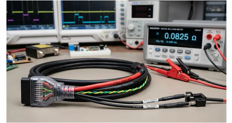
In the last two years, I have reviewed eleven test bench OBD harnesses that were shipped back from labs with “ECU reset during flash” written on the fault tag. Nine of them measured fine on continuity and failed under load. The OBD cable is passive, so it is usually the last part to be measured. A continuity test passes. The connector clicks. The pinout matches the drawing. Then the ECU resets during a flash cycle, or the CAN bus shows a burst of error frames only when an actuator is switched on. This article covers the three parameters that decide whether the device under test sees a clean supply and a quiet ground: conductor cross-section, total loop resistance, and ground separation between pin 4 and pin 5.
This is not a retail buying guide. It is the specification logic I use when reviewing OBD cable assembly drawings from automotive labs, HIL rig builders, and production test stations. After two decades of building harnesses in a factory environment, I can usually spot the problem from the drawing alone before a single wire is cut.
Quick Reference for a 2 m Bench Cable
- Power/ground conductors: 18 AWG minimum; use 16 AWG for currents above 5 A or lengths over 2 m.
- CAN_H and CAN_L: 22 AWG twisted pair, unshielded or shielded with a drain wire.
- Total loop resistance, pin 16 to pin 4/5: ≤0.1 Ω at 5 A; ≤0.05 Ω at 10 A.
- Pin 4 and pin 5: keep separate unless the ECU requires an external jumper.
- Shield termination: bench-side single-point ground only.
- Test requirement: loop resistance measured on every assembly, not sample tested.
A Failure That Looks Like a Software Problem
I will start with a real failure pattern. A bench was set up with a 3-meter OBD extension cable built from 24 AWG conductors. The power supply was set to 13.8 V. The ECU flashed without issue at room temperature. During a cold-crank simulation, the ECU reset randomly. The lab swapped the ECU, the power supply, the CAN interface, and the termination resistor. The reset remained.
At the ECU connector, the supply rail dropped to 9.9 V during the 3.5 A inrush. The cable loop resistance was about 0.34 Ω, and the connector contact resistance added another 0.08 Ω. At 3.5 A, that is a 1.47 V drop. The power supply was fine. The cable was not. This is the classic pattern: the cable passes continuity, so it is removed from the suspect list too early.
AWG Is Not a Cosmetic Choice
AWG defines the cross-sectional area of the copper conductor, which defines DC resistance per unit length. For a test bench cable, AWG is not about mechanical robustness. It is about voltage drop under load. Pin 16 of the J1962 connector is often used to supply power to the ECU during flashing and testing. Flash programming can pull 2–5 A. Actuator tests can pull 10 A or more. If the wire gauge is too small, the voltage at the ECU drops below the minimum operating threshold and the ECU resets or behaves intermittently.
| AWG | Nominal copper cross-section (mm²) | DC resistance per meter (mΩ/m) | Loop resistance for 2 m assembly (Ω) |
| 24 | 0.205 | 85 | 0.34 |
| 22 | 0.326 | 54 | 0.22 |
| 20 | 0.518 | 34 | 0.14 |
| 18 | 0.823 | 21 | 0.085 |
| 16 | 1.31 | 13 | 0.053 |
Values are calculated for solid copper at 20°C. Our production wire is stranded, so measured resistance is typically 3–5% higher. Connector contact resistance is not included.
Mixed-Gauge Assembly for Test Bench OBD Cables
For a 2 m cable, 24 AWG drops 1.7 V at 5 A, while 18 AWG drops 0.43 V. That is the difference between a working bench and a random ECU reset. Signal lines such as CAN_H, CAN_L, and K-line do not need 16 AWG. They carry low current, but they do need correct twist and characteristic impedance. A practical bench cable is usually a mixed-gauge assembly: 16 AWG or 18 AWG for power and ground, and 22 AWG twisted pair for CAN.
Loop Resistance: The Number to Specify, Not Just AWG
Specifying AWG alone is not enough. The total loop resistance includes the power wire, the return wire, the connector contacts, and the crimps. A cable made from 18 AWG wire can still fail if the terminals are poorly crimped or the connector is worn. The loop resistance is the number that should be written into a bench harness specification.
The voltage drop is calculated as:
V_drop = I_load × (R_power_wire + R_return_wire + R_contact_total)
A 2 m 18 AWG cable has about 0.085 Ω of wire loop resistance. Add two connector pairs at 10 mΩ each, or 0.020 Ω, and two crimps at 5 mΩ each, or 0.010 Ω. The total loop is 0.115 Ω. At 5 A, the voltage drop is 0.575 V. If the bench supply is set to 12.0 V, the ECU sees 11.43 V. Some ECUs specify an 11.5 V minimum during flash. That is already marginal before the wire warms up.
For a 2 m bench cable at 5 A, total loop resistance from power supply output to DUT power input should be ≤0.1 Ω. For 10 A, use ≤0.05 Ω. For other lengths, recalculate from the allowed voltage drop.
Measuring Loop Resistance on the Bench
To measure loop resistance, use a milliohm meter with Kelvin clips. Short pin 16 to pin 4 and pin 5 at the DLC end, then measure at the power supply end. If no milliohm meter is available, pass a known constant current of 1.00 A through the power path and measure the voltage drop across the cable. R = V / I. Do not trust a standard two-wire continuity measurement.
Ground Separation: Pin 4 vs Pin 5
The J1962 connector defines pin 4 as chassis ground and pin 5 as signal ground. In a vehicle, these two grounds are often connected at different points in the body harness. Chassis ground carries high currents from motors, solenoids, and injectors. Signal ground is a cleaner reference for the ECU sensors and communication circuits. If pin 4 and pin 5 are shorted inside the OBD cable, return current from the bench power supply is forced through the signal ground conductor. That raises the ECU signal reference and adds noise to CAN and analog inputs. This is the same failure mechanism I detailed in a separate write-up on J1962 pin 4 and pin 5 phantom sensor faults.
On a test bench, the problem is more severe because the bench ground and the ECU ground may not be at the same potential. If the cable ties pin 4 and pin 5 together internally, any ground offset between the bench and the DUT flows through the signal ground path or the cable shield. The result is common-mode noise that looks like a termination problem or an EMC failure. A small ground offset can be mistaken for an ECU fault, which leads to unnecessary replacements. I covered that misdiagnosis pattern in how to avoid ECU replacement from ground offset.
| Pin | J1962 definition | Common bench mistake |
| 4 | Chassis ground | Tying it directly to the power supply return instead of the bench chassis ground, which injects load current into the signal reference. |
| 5 | Signal ground | Using it as a high-current return for pin 16. This shifts the ECU analog and digital ground reference. |
| 6 | CAN_H | Running it untwisted or routing it parallel to switched power wires. Error frames appear only when an actuator switches. |
| 14 | CAN_L | Same as CAN_H. The pair must stay twisted with consistent characteristic impedance. |
| 16 | Battery voltage | Under-sizing the conductor because “it is only a bench cable.” Flash current can pull 5 A or more. |
Shield Termination Rules for Test Benches
Recommended practice is to keep pin 4 and pin 5 separate within the cable assembly. If the ECU under test requires a common ground, add an accessible jumper at the DLC end or at the breakout box. Do not bury the tie inside the overmold. If the cable has a shield, tie the shield drain wire to the bench single-point ground at the bench side only. Leave the DLC end of the shield floating unless the test specification requires otherwise. When the shield is terminated incorrectly, common-mode voltage can rise and kill CAN communication entirely. I have diagnosed this failure in the field and documented it in how common-mode voltage kills J1939 communication.
Step-by-Step Specification for a Test Bench OBD Cable
Step 1: List the electrical loads. Record the maximum current on pin 16, the maximum return current on pins 4 and 5, the CAN baud rate, and whether any other pins carry power or signals. Do not guess. Read the ECU datasheet or measure a known good setup.
Step 2: Set a voltage drop budget. Use the ECU minimum operating voltage. For example, if the bench supply is 12.0 V, the ECU minimum is 10.8 V, and you want 0.4 V of margin, the allowed drop is 0.8 V. At a maximum load of 5 A, the allowed loop resistance is 0.8 V ÷ 5 A = 0.16 Ω.
Step 3: Choose the wire gauge from the loop resistance budget. Subtract connector and termination resistance first. Then select the wire gauge that meets the remaining budget. For a 2 m bench cable, 18 AWG for power and ground is a reasonable starting point. Use 16 AWG if the cable is 3 m or longer, or if the current exceeds 5 A. Use 22 AWG twisted pair for CAN_H and CAN_L.
Step 4: Define the ground scheme. State whether pin 4 and pin 5 are separate. Write down the shield termination point. If the ECU requires pin 4 and pin 5 to be tied, specify an external jumper.
Step 5: Specify the connector. Use a J1962 connector with proper keying and positive lock. Tin-plated terminals are acceptable for bench use, but gold plating is better for low-level signal contacts if the harness is mated and unmated often. Specify the terminal part number if possible.
Step 6: Add mechanical requirements. Include strain relief, cable jacket material, minimum bend radius, and labeling. A bench cable is handled daily, so a PVC or polyurethane jacket is usually better than thin service-tool insulation.
Step 7: Request test data from the harness supplier. Ask for loop resistance measurement per assembly, crimp pull test data, and material certificates. If the harness will be used on a production validation line, request a control plan or PPAP-style documentation.
Mistakes I Have Seen in Production Drawings
- Using a one-to-one extension cable without checking the pin 4/pin 5 tie. I have seen a bench where this single mistake shifted the signal ground by 0.4 V during a fuel injector test.
- Assuming continuity equals low resistance. A crimp can pass a 1 mA continuity test but have 0.2 Ω at 5 A because of broken strands or a partial crimp. We found one on a 2 m harness that caused a 0.9 V drop at 4.5 A.
- Running unshielded CAN wires parallel with switched power wires for actuators. Crosstalk can be mistaken for a termination error. In one HIL rig, error frames appeared only when the EGR valve was pulsed, and the CAN pair ran 30 mm away from the valve power wire.
- Using copper-clad aluminum conductor to save money. A customer sent us a 2 m CCA cable for a 5 A bench. It measured 0.18 Ω loop instead of 0.085 Ω for copper. That is an extra 0.9 V drop at full load. The ECU reset at every cold crank.
- Overlooking connector contact resistance. A worn DLC connector or a cheap terminal can add 50–100 mΩ per contact. On a 10 A bench, that is 0.5–1.0 V lost before the wire even starts.
- Grounding the shield at both ends. This creates a ground loop that injects noise into the signal reference. I have seen a bench where the shield current was higher than the CAN signal current, and the bus became intermittent.
How to Confirm the Harness Is No Longer the Problem
Measure the loop resistance at room temperature and after warm-up. Copper resistance increases about 0.4% per degree Celsius. A 20°C temperature rise adds roughly 8% resistance. If the cable runs near a hot bench or an exhaust simulator, recheck the budget at operating temperature.
Perform a loaded voltage drop test. Use an electronic load or a power resistor to draw the maximum bench current. Measure voltage at the DUT connector during the entire test. It should stay above the ECU minimum.
Capture CAN waveforms at the DUT connector during a flash cycle. Look for common-mode offset, excessive ringing, or missing acknowledge bits. These can be caused by poor ground separation. When probing CAN signals, scope bandwidth matters. I discussed the difference between 50 MHz and 100 MHz scopes in how scope bandwidth affects CAN bus glitch capture.
Run repeated cold-crank cycles. If the ECU resets, record the DUT supply voltage with a storage oscilloscope. If the reset coincides with a voltage dip below the datasheet minimum, the cable or the power supply is still marginal.
If a thermal camera is available, inspect the harness under load. A hot spot at a connector or splice indicates localized resistance.
Factory Notes on Building These Assemblies
For bench harnesses, we build from raw wire, terminals, and overmold compound rather than repackaging a catalog part. Every assembly goes through a loop-resistance test on every unit, not sample testing. A loop resistance printout can be shipped with each harness if the engineer requests it. The test limit is normally set tighter than the bench requirement, for example 0.08 Ω total loop for a 2 m 18 AWG assembly, to leave headroom for connector aging.
OEM customization is the normal workflow, not an exception. Engineers send drawings with mixed AWG, custom lengths, wire colors, overmolded labels, brand markings, and specific pin 4/pin 5 treatments. We build prototypes from the approved drawing before committing to production. This is not a one-size-fits-all retail product. The rest of our production background and certifications are on the factory page, including our IATF 16949 certification and ISO 14001 environmental management.
Related Configurations That Cover Most Bench Needs
For reference, the most common bench configurations we see are: a J1962 male to unterminated pigtail with 16 AWG power and ground, 22 AWG twisted pair for CAN, and pin 4/pin 5 left separate; an OBD extension cable with breakout test points for voltage and CAN monitoring; and a DLC breakout harness with a detachable pin 4/5 jumper. The exact configuration is usually driven by the ECU pinout and the bench grounding scheme, not by a catalog number.
Frequently Asked Questions
What AWG should I use for a 3 m test bench OBD cable?
For power and ground, use 18 AWG minimum if the current is below 5 A. Use 16 AWG for 3 m and 5–10 A. In the Step 2 example above, a 3 m cable at 5 A would need a wire loop resistance below about 0.12 Ω after subtracting connector losses, which points to 16 AWG. CAN can remain 22 AWG twisted pair.
Can I tie pin 4 and pin 5 together inside the cable?
Not by default. Keep them separate and add an accessible jumper if the ECU requires a common ground. Tying them inside the overmold removes a debugging option and can inject noise. I have seen a bench where tying pin 4 to pin 5 inside the overmold shifted the signal ground by 0.3 V during a cooling fan test.
How do I measure loop resistance without a milliohm meter?
Pass a known constant current, such as 1.00 A, through pin 16 to pin 4/5. Measure the voltage drop across the cable with a DMM. Divide voltage by current. Use Kelvin connections if possible. For example, if you measure 85 mV at 1.00 A, the loop resistance is 0.085 Ω. A two-wire continuity test will not tell you this.
Does shielding help with CAN errors?
It can, but only if the shield is terminated correctly. For bench use, a shield tied at one end to the bench ground often reduces common-mode noise. Tying both ends creates a ground loop. The CAN twisted pair is more important than the shield. On a bench where the shield was tied at both ends, the ground loop current caused the CAN bus to fail only when the motor drive was enabled. This is exactly the common-mode failure I described in how common-mode voltage kills J1939 communication.
What is the maximum acceptable loop resistance for a bench OBD cable?
It depends on current and voltage margin. As a reference, for a 2 m cable at 5 A, keep total loop resistance below 0.1 Ω. For 10 A, use 0.05 Ω or lower. In the example in the Loop Resistance section, an 18 AWG cable with good crimps measured 0.115 Ω and was marginal at 5 A.
Why does my ECU brown out only during flash programming?
Flash programming often draws more current than normal operation, especially during erase and write. A marginal harness loop resistance may be fine at 1 A but fails at 3–5 A. Measure voltage at the ECU during flash, not at the power supply. The failure case at the top of this article was exactly this: a 24 AWG cable passed continuity but dropped the ECU rail to 9.9 V at 3.5 A.
Can I use copper-clad aluminum wire for a bench harness?
I would not. CCA has higher resistance and is more brittle. The loop resistance budget is usually tight enough that copper is the safer choice. If you must use CCA, increase the gauge by two sizes and re-test loop resistance. A 2 m CCA cable we tested measured 0.18 Ω loop at 5 A, which dropped 0.9 V more than the equivalent copper cable.
Do I need separate ground returns for high-side and low-side drivers?
Sometimes. If the harness carries high-current switched loads on pins other than pin 16, run separate returns for those loads to avoid shifting the signal ground. This is part of the ground separation requirement. In a body control module test, a shared ground caused the CAN reference to shift by 0.25 V when the wiper motor was activated.
What length is too long for a bench OBD extension?
For 500 kbps CAN, 5–10 m can work if the cable is proper twisted pair and terminated. The bigger problem is power drop on long runs. At 10 m and 5 A, even 16 AWG loop resistance is about 0.26 Ω, which drops 1.3 V. Use a thicker gauge or a local power supply at the DUT. This matches the loop resistance calculation in the AWG section.
What documentation should I ask from a cable supplier?
Ask for a crimp pull test report, loop resistance test data, material certifications such as RoHS, REACH, and UL, and a PPAP or control plan if the harness will be used on a production validation line. The supplier should be able to provide these without much back-and-forth. We ship a loop resistance printout with every bench harness if requested.
Conclusion and Engineering Support
If a test bench shows intermittent resets, CAN errors, or EMC problems, measure the cable before changing the ECU. Write a specification that includes AWG, total loop resistance, and pin 4/pin 5 separation. These are cheap to verify and expensive to ignore.
If you are drafting a test bench OBD cable specification and want a factory engineer to review the drawing, send it through the contact page. For faster mark-up and a loop resistance calculation for your specific length and current, use WhatsApp. I will mark up the pin 4/5 treatment and check the AWG against your voltage drop budget. This is the kind of review that is easier before the first prototype than after a failed EMC run.
