

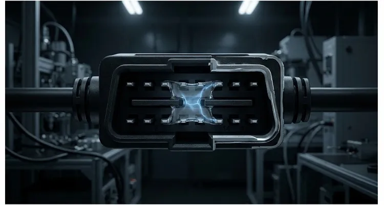
In March of last year, a BMS test bench in an unconditioned Detroit lab produced a 180 mV offset on channel 4 between 10 p.m. and 6 a.m. The daytime readings were within 1.2 mV of the reference. The engineer had already reflashed firmware twice and swapped the ADC before I pulled the harness apart and found condensation bridging pin 14 to pin 6 at the overmold. The creepage distance measured 0.42 mm—roughly half the 0.8 mm the design called for. At 12V system voltage, that works out to 2.7 microamps of leakage current sneaking into a high-impedance analog sense line.
Two point seven microamps. That was enough to destroy the accuracy of a system that was otherwise designed correctly.
This is the failure mode nobody puts on a datasheet, because it happens after the part leaves the factory. It’s not a component defect. It’s a system-level environmental failure. And if you build or buy OBD harnesses for analog measurement, data logging, or ECU validation, you will meet it eventually.
What Actually Happens Between Two Pins
To understand why this failure is so insidious, stop thinking about “shorts” and “opens.” A short is binary—zero ohms, smoke, blown fuse. That’s easy to find. What we’re describing is a resistive path that forms slowly, then disappears when the humidity drops. It behaves more like a semiconductor than a wire.
The Condensation Pathway
The connector body doesn’t need to be immersed. Water vapor follows the jacket, rides the conductor strands, and settles at the coldest point—the overmold. Below the dew point, a film no thicker than a fingerprint forms between the terminals. That film is the leakage path.
Most connector housings are made from PBT or nylon. When dry, these are excellent insulators—surface resistivity in the range of 10^13 to 10^15 ohms per square. But add a microscopic layer of water mixed with trace ionic contamination—flux residue from soldering, dust from the assembly floor, even skin oils from a technician’s thumbprint—and that resistivity can drop by six orders of magnitude.
From Surface Resistivity to Leakage Current
In a standard OBD-II connector, the pin pitch is tight. Pins 5 and 6, or 14 and 6, sit close enough that a water film can bridge the creepage distance. The resistance of that path might be 4 to 6 megohms. At 12V, that’s 2 to 3 microamps.
Now, two microamps into a digital CAN line is nothing. The transceiver doesn’t even register it. But two microamps into a high-impedance analog input—say, a thermistor divider with a 100 kilohm source impedance—creates a voltage offset of 200 millivolts. That’s a full-scale error on many 3.3V ADC channels.
The worst part? It’s not constant. It breathes with the ambient humidity. You’ll chase it for weeks, and every time you bring the unit into a dry lab, it works perfectly.
Why High-Impedance Inputs Are So Vulnerable
Let’s put a number on it, because the math is more persuasive than adjectives.
The Voltage Divider Math
If your analog front-end has an input impedance of one megohm, then a leakage path of five megohms from an adjacent 12V line forms a voltage divider. The input pin sees:
12V × (1MΩ / (1MΩ + 5MΩ)) ≈ 2.0V
That’s not noise. That’s a DC bias that overwhelms the sensor output—a problem that also shows up when you compare single-ended versus differential ADC inputs in automotive ECUs. A thermocouple puts out 40 microvolts per degree Celsius. A 2V offset looks like a 50,000-degree temperature swing. Your firmware doesn’t know the difference.
This is why the same harness that works perfectly for CAN communication can fail catastrophically on an analog data logger. The CAN transceiver has an input impedance of maybe 20 to 30 kilohms. It takes a leakage path of less than 1 kilohm to even notice. The analog channel is four orders of magnitude more sensitive.
Pin-to-Pin, Not Pin-to-Ground
And here’s the part that makes engineers want to quit: the leakage path isn’t necessarily to ground. It can be from one signal pin to another. Pin 6 (CAN high) idles at 2.5V. Pin 14 (CAN low) idles at 2.5V. No differential voltage, no problem. But in a fault state or during certain bus activity, CAN high can swing to 3.5V. That’s a volt of difference across a contaminated creepage path. The leakage current flows, and if your analog sense line happens to be pin 5 (signal ground) or a repurposed OEM pin next to it, you get a ground bounce that looks like a real signal. This is the same mechanism behind the phantom sensor faults on J1962 pin 4 and pin 5 that show up when adjacent pins share a contaminated creepage path.
The Root Cause Is Not What You Think
When a leakage current appears, the connector gets blamed first. It’s the part you can hold. But in the cables I’ve dissected, the connector housing was rarely where the problem started. It was the junction where the jacket entered the overmold, or the strip length inside, or contamination that was sealed in before the plastic was even injected.
Four Upstream Causes
- Poor cable jacket adhesion. If the outer jacket doesn’t bond tightly to the inner conductors at the point where it enters the connector body, you create a capillary gap. Water vapor enters this gap and condenses. Even if the connector body is sealed, the cable itself becomes a moisture pump.
- Insufficient creepage distance at the overmold. The overmold is where the individual conductor insulation is stripped back and crimped to the terminal. If the strip length is too long, or the overmold material doesn’t completely encapsulate the crimp, you end up with exposed metal surfaces that are closer together than the design intended. A 0.5 mm reduction in creepage distance can be the difference between a 10-year life and a 10-day failure—as we saw with the 0.42 mm measurement in Detroit.
- Ionic contamination during assembly. This one is invisible to the naked eye and completely invisible to a continuity tester. A fingerprint on a terminal before overmolding leaves behind sodium chloride and organic acids. Add moisture, and you have an electrolyte. The leakage current is now electrochemical, not just resistive. It will actually grow over time as corrosion products build up.
- Material choice. Not all PBT is the same. Some grades are hygroscopic. Some have glass fill that reduces creepage resistance. We’ve tested connectors that cost two cents less but had a comparative tracking index (CTI) half the value of a proper material—often 300V instead of 600V. If you don’t specify the material, someone else will. And they’ll specify the cheap one.
How We Find It—And Why It’s So Easy to Miss
The first time I encountered this problem, I did what everyone does: I grabbed a multimeter and measured resistance between the suspect pins. I got “OL”—over limit. No continuity. So I declared the connector healthy and moved on.
That was a mistake, and it cost me three days.
Why a Multimeter Misses the Leak
A standard multimeter measures resistance by applying a tiny test current—often less than one microamp—at a very low voltage. That’s fine for finding a dead short, but it will never expose a 5-megohm leakage path that only forms when moisture is present and a real voltage is applied.
The Five-Step Diagnostic Sequence
- Measure leakage current, not resistance. Use a source-measure unit (SMU) or a simple bench setup: a clean 12V supply in series with a microammeter and the suspect pin pair. Apply 12V, wait 30 seconds for the path to stabilize, and read the current. If you see anything above 100 nanoamps on a connector that should be dry, you have a problem.
- Run a damp heat soak. Put the harness in an environmental chamber at 40°C and 93% relative humidity for 4 hours. Then measure leakage current while still in the chamber. Don’t pull it out and let it dry before testing. The failure only exists while the moisture is present.
- Measure pin-to-pin, not just pin-to-ground. The most common leakage path is between adjacent signal pins, not from a pin to the connector shell. If you only test against ground, you’ll miss half the failures.
- Use the right test voltage. Leakage current is not always linear with voltage. Test at the actual system voltage, not a low-voltage continuity setting. A path that reads open at 0.5V may conduct at 12V.
- Look for the physical evidence under a microscope. After you’ve confirmed a leakage current, cut the connector open. Look at the overmold junction. You’re looking for a hairline gap between the jacket and the overmold material, or any sign of corrosion on the crimp. If you see green or white powdery deposits, that’s electrochemistry. The contamination was there before the moisture ever arrived.
Five Mistakes That Make It Worse
Most of the time, the problem gets worse not because of what was left out, but because of what was added in a panic. Here are the five interventions I’ve seen backfire.
- Mistake 1: Sealing the outside, ignoring the inside. Adding silicone sealant around the connector shell does nothing if moisture is already inside the cable jacket. It actually makes things worse by trapping the vapor inside. Moisture that can’t escape will find the path of least resistance—which is exactly the pin-to-pin gap you’re trying to protect.
- Mistake 2: Using “waterproof” connectors without understanding the rating. An IP67 connector is rated for immersion in liquid water. It says nothing about water vapor. Vapor penetrates through materials that stop liquid water cold. If your application has temperature cycling, you get condensation inside even the best-sealed housing. It’s not a seal failure. It’s physics.
- Mistake 3: Cleaning with the wrong solvent. Isopropyl alcohol is great for removing flux, but it can also strip plasticizers out of connector materials and leave behind a residue that actually attracts moisture. Use only cleaners that are approved for the specific plastic and contact materials. Or better yet, don’t clean after assembly. Prevent contamination before it happens.
- Mistake 4: Increasing pull-up or drive strength to “swamp” the leakage. This works, sometimes, for digital signals. But for a high-impedance analog input, you can’t just lower the source impedance without changing the sensor. And a lower source impedance doesn’t fix the underlying issue—it just hides it until the leakage path grows worse.
- Mistake 5: Ignoring the cable, focusing on the PCB. The PCB is often the last place the problem actually lives. I’ve seen engineers swap out ADCs, add guard traces, and redesign front-end filters, when the entire problem was a three-dollar harness that was absorbing moisture like a sponge. Test the harness first. It’s cheap. It’s fast. And it’s usually the answer.
The Fix Is a Process, Not a Part
The harness that caused that 180 mV offset in Detroit wasn’t fixed by sealing the outside. It was fixed by changing the material grade at the overmold and locking the creepage distance. If you’re specifying a cable for this kind of measurement, those are the two numbers you need to verify—not just the connector part number.
Manufacturing Controls That Prevent Leakage
- Material lock. The connector housing material is specified by grade, not by generic name. PBT GF30 with a CTI rating of 600V or higher is mandatory for any application with tight pin spacing. No substitutions without a documented engineering change order.
- Overmold pressure and temperature control. The overmold isn’t just a cosmetic cover. It’s a structural seal. If the mold temperature is too low, the plastic doesn’t flow completely into the junction and leaves voids. If it’s too high, it can deform the connector body. We run these parameters inside a narrow window and log them for every batch.
- Creepage distance verification. Before a new connector design ships, we cross-section samples and measure the actual creepage distance between adjacent pins under a microscope. The design target is a minimum of 0.8 mm for 12V systems, more for higher voltages. If it doesn’t measure up, it doesn’t ship.
- Salt spray testing on every new design. This is where the material claims get validated. We run the assembled harness through a neutral salt spray test (NSS) according to ASTM B117, typically 48 to 96 hours depending on the application, and then measure insulation resistance while the assembly is still wet. In a recent qualification, we tested 12 assemblies and found 3 failed after 72 hours due to a material substitution that had slipped through. The design was sent back to engineering. This test is the gate—the one that decides whether the design ships.
- PPAP documentation. For automotive and industrial customers, we provide full production part approval process documentation. That includes the material certifications, the dimensional reports, the salt spray test results, and the process capability data. You get a paper trail that proves the cable you’re buying is the cable we qualified. Not a “similar” one. Our quality system is certified to ISO 9001, ISO 14001, and IATF 16949, which means the process controls described here are not optional—they’re audited.
How to Know You’ve Fixed It
The test for success is not “the problem went away.” The test for success is that the problem cannot come back, even when you deliberately try to make it come back.
The Three-Point Validation
- Run the damp heat soak described earlier. 40°C, 93% RH, 4 hours. Measure pin-to-pin leakage current between every adjacent pair at the full system voltage. The target is less than 10 nanoamps. Not microamps. Nanoamps. Ten nanoamps is low enough that even a 1-megohm source impedance sees less than a 10-microvolt offset. That’s a level you can live with.
- Run a thermal cycle while the harness is still damp. -10°C to 60°C, 10 cycles, 1 hour dwell at each extreme. This stresses the junction between the jacket and the overmold. If there’s a capillary gap, this cycle will open it up.
- Run the salt spray test if this is an automotive or marine application. After the test, wipe the exterior dry and measure leakage current again. The test fails if any adjacent pin pair shows more than 100 nanoamps.
If your harness passes all three, you’re done. The problem is gone. Not because you lucked out with a good sample, but because the materials and process are correct.
Why This Matters for the Harness You’re Buying Now
The difference between a cable that fails in the field and one that survives for a decade is almost never visible from the outside. Both look identical. Both pass continuity. Both plug in and work.
Externally, both cables look identical. The difference is in the mold pressure, the material certificate, and the creepage distance verification.
Measured Leakage Current Comparison
| Test Condition | Dry Leakage Current | After 4h Damp Heat (40°C/93% RH) | After Salt Spray 48h |
| Correct PBT GF30, 0.8 mm creepage | <1 nA | <10 nA | <50 nA |
| Incorrect PBT, 0.42 mm creepage | <1 nA | 2.7 µA | 15 µA |
We build OBD cables for engineers who can’t afford to chase phantom microamp leakage currents through their analog front-ends. Every batch gets 100% continuity and insulation resistance testing before it ships. The design gets salt spray tested before it’s ever offered to you. The material data is documented, not assumed.
If you’re dealing with a leakage problem right now, or if you’re specifying a cable for a high-impedance measurement system and want to make sure you never have to, reach out. We’ll talk through your application, look at your pinout, and tell you honestly whether the cable is your risk—or whether you should be looking elsewhere.
Because I’d rather spend an hour helping you avoid this problem than have you spend six hours chasing it later.
Frequently Asked Questions
Q: What’s the difference between leakage current and a short circuit?
A short circuit is a near-zero resistance path that causes immediate, obvious failure—blown fuses, melted connectors, dead modules. Leakage current is a high-resistance path, typically in the megohm range, that doesn’t trip any protection but still lets enough current flow to offset sensitive analog readings. You can have a catastrophic measurement error with a connector that measures perfectly fine on a continuity tester.
Q: How much leakage current is too much?
For a high-impedance analog input with a source impedance above 10 kilohms, any leakage current above 100 nanoamps is worth investigating. Above one microamp, you’re almost certainly seeing measurement corruption. For reference, a 1-megohm input with a 1-microamp leak sees a 1-volt offset. That’s not a subtle error.
Q: Can I use a regular multimeter to find this problem?
No. A multimeter in resistance mode applies too little voltage and too little current to expose a high-resistance leakage path. You need to measure current at the actual system voltage. A simple bench setup with a power supply and a microammeter works. Better yet, use an insulation resistance tester or megger if you have access to one.
Q: Why does the problem come and go?
The leakage path is moisture-dependent. When the humidity drops, the surface dries out and the resistance goes back up. The failure appears to “fix itself.” Then the humidity returns, the moisture re-condenses in the same micro-gaps, and the problem reappears. This cycling is often what makes the issue so frustrating to diagnose.
Q: Does conformal coating on the PCB help?
Conformal coating helps the PCB, but it does nothing for the connector and cable assembly. If the leakage path is inside the connector body, coating the board is like locking the front door while the back door is wide open. Fix the connector first.
Q: Are “sealed” connectors immune to this?
No connector is permanently immune to water vapor. Sealed connectors are much better than unsealed ones, but they can still suffer from condensation if the temperature cycles and there’s any moisture trapped inside from manufacturing. The best protection is proper material selection, tight creepage distances, and a clean assembly process.
Q: Is this only a problem for analog signals?
Analog signals are by far the most sensitive, but digital systems aren’t immune. A leakage path can cause slow rise times on open-drain lines, false triggers on high-impedance digital inputs, and increased sleep current in battery-powered devices. Analog is where you see it first, but it can affect any high-impedance node.
Q: What testing should I ask for from a cable supplier?
Ask for insulation resistance measurements at the system voltage, not just continuity. Ask whether the connector material has a documented CTI rating. Ask if the design has been through salt spray testing and thermal cycling. And if you’re in automotive or industrial, ask for PPAP documentation. A supplier that can’t provide these is a supplier you’re gambling with.
Q: What CTI rating do you require for OBD connectors used in EV battery test setups?
For EV battery test setups where analog sense lines are routed alongside high-voltage signals, we specify a minimum CTI of 600V. This ensures the material can withstand surface tracking even with ionic contamination present. Lower CTI materials—300V or below—are a red flag for any application with tight pin spacing and humidity exposure.
Q: Do you perform salt spray testing on the entire harness or just the connector body?
We test the entire assembled harness, including the overmold junction and the first 300 mm of cable. The failure mode we’re hunting is often at the cable-to-connector transition, not inside the connector body itself. Testing only the connector misses the most common leak point.
Q: How long does salt spray testing take?
A standard neutral salt spray test for this type of connector runs 48 to 96 hours depending on the severity level you’re targeting. After the test, we measure insulation resistance while the part is still wet. This is what separates a connector that survives and a connector that just looks like it survives.
Q: What’s the best first step if I suspect this problem in my own system?
Don’t touch the firmware. Don’t rework the board. Put the entire harness in a damp heat environment—40°C, 93% RH—for four hours, then measure pin-to-pin leakage current at system voltage while it’s still in the chamber. If you see anything above a few hundred nanoamps, you’ve found your problem. And you’ve just saved yourself a week of pursuing a fault that disappears when the humidity drops.
Ready to Talk Specifics?
If you’re measuring more than 100 nA between any two pins on your current harness, send me the pinout and your test voltage. I’ll tell you whether the creepage distance is adequate for your system, and what material change would fix it if it’s not. Reach us on WhatsApp for a direct conversation with the engineering team, or use the contact page and we’ll respond within one business day. We work with OEM and engineering teams on custom pinouts, connector materials, cable lengths, and full documentation packages—no retail, no price lists, just application-specific engineering support.
