

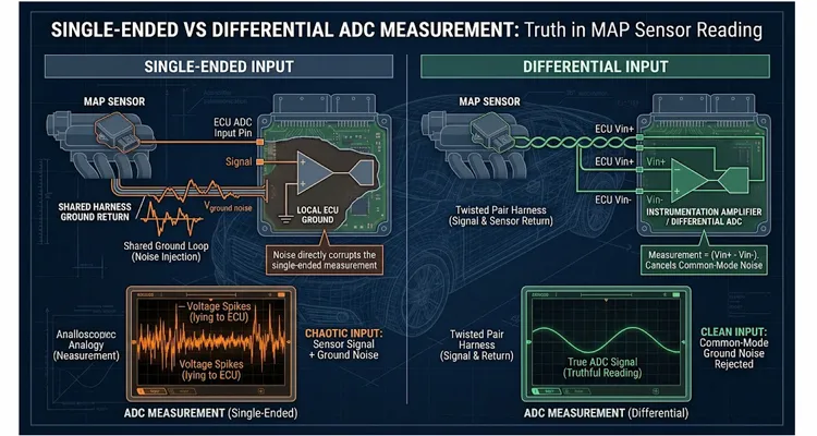
I remember the exact bench setup. It was a humid Tuesday in July, and we had a customer’s ECU on the harness simulator. The firmware team was chasing a ghost—a manifold absolute pressure reading that wandered by twelve kilopascals at idle. Twelve kPa. On a naturally aspirated engine, that’s the difference between a smooth idle and a stumble that makes the whole dashboard vibrate.
They had already swapped the MAP sensor. Twice. They had reflashed the calibration. They had checked the vacuum line with a hand pump and a smoke machine. Nothing. The MAP sensor on the bench was dead stable. The ECU on the bench was dead stable. Put them together in the vehicle, and the trace looked like someone had drawn it with a shaky pen after three cups of coffee.
The problem was not the sensor. It was not the firmware math. It was the fundamental assumption that a single-ended analog input—the default choice in a huge number of automotive ECU designs—could tell the truth in an environment that is actively trying to lie to it.
This article is about that lie. It is about the difference between measuring a voltage with one wire and a ground reference, versus measuring it with two wires and letting the difference carry the signal. It is about why your MAP reading, your throttle position, your EGR feedback, or your oxygen sensor heater current can look perfectly fine on a lab bench and completely unhinged in a vehicle. And it is about what you can actually do about it, from sensor selection to PCB layout to connector pinning.
If you have ever stared at a data log and thought, “This cannot possibly be what the engine is doing,” you are probably right. The engine is not doing that. Your analog front end is doing that.
The Moment You Realize the Ground Is Not a Ground
Before we go any further, I need to address the phrase “single-ended” honestly. A single-ended input doesn’t measure the sensor voltage. It measures the difference between the sensor wire and whatever the ADC thinks “ground” is. On a schematic, that ground node is drawn as zero volts. Inside an engine bay, it isn’t zero, and it doesn’t sit still.
On a real wiring harness, inside a real engine bay, that reference point is being pulled around by every load that shares the same return path. Here is the scenario that makes this obvious.
A customer sends us a datalog from a four-cylinder engine with a single-ended MAP sensor input. The MAP signal looks clean at key-on, engine off. Start the engine, and at idle there is a sawtooth ripple on the MAP trace. It is about forty millivolts peak to peak. When the cooling fan kicks on, the entire trace jumps by sixty millivolts. When the injectors fire, there is a tiny spike on every injection event. This is not a sensor problem. This is a voltage shift on the return path.
The MAP sensor is mounted on the intake manifold. Its ground wire runs back to the ECU through the engine harness. The ECU also drives the injectors, the idle air valve, the cam actuators, and the low-side switches for the fan relay. Every time one of those loads switches, current flows through the harness ground return. The harness ground has resistance—not much, perhaps twenty to forty milliohms over a meter-long run with an eighteen-AWG wire. But when the fan relay pulls half an amp, that is a voltage drop of fifteen to twenty millivolts across that shared return path. When the injectors fire, the instantaneous current is higher, and the drop is proportionally worse.
Now, here is the key. If the MAP sensor’s ground reference is connected to the same physical node as the injector driver return, the ECU’s ADC sees not the MAP voltage, but the MAP voltage plus whatever voltage appears across that shared ground impedance. The sensor is producing a perfectly good output. The ECU is just measuring it wrong.
A differential input does not eliminate this problem. It sidesteps it. In a differential input, you don’t care what the ground is doing. You wire the sensor return to a second pin, and the ADC subtracts one pin from the other. If the fan relay injects a 60 mV spike into both wires, the subtraction removes it. The spike never reaches the conversion result. The signal is allowed to ride on top of whatever common-mode garbage is present, as long as it stays within the input common-mode range of the ADC or instrumentation amplifier.
Where the Difference Actually Matters
The difference between single-ended and differential is not theoretical. It shows up in a handful of very predictable places in an automotive ECU. Before I get into the specific failure modes, here’s a side-by-side I keep on my bench screen for every new analog project:
| Parameter | Single-Ended Input | Differential Input |
| Pins required | 1 signal + shared ground | 2 signal + return |
| Ground noise rejection | None; offset adds directly to reading | High; common-mode cancels |
| Best for | Slow, low-impedance sensors (coolant temp, etc.) | Critical, wide-range sensors (MAP, current sense) |
| Harness requirement | Single wire + chassis/sensor ground | Twisted pair with dedicated return |
Let me walk you through the places where this choice has real consequences in an automotive ECU.
Sensor Ground Reference Placement
This is the biggest one. Many production sensors—especially older MAP sensors, temperature sensors, and even some throttle position sensors—have a dedicated sensor ground wire that returns to the ECU. On the ECU schematic, that sensor ground is typically routed back to an analog ground plane. But if that analog ground plane is tied to the digital ground or the power ground at a single point only, and that point happens to be on the wrong side of a high-current return path, you have created a ground offset generator.
I have seen ECUs where the sensor ground connection was placed within millimeters of the injector driver ground return. The result was a MAP reading that correlated perfectly with fuel injection duty cycle. The more fuel the engine wanted, the more the MAP reading was pushed around. The ECU then corrected the fuel based on that wrong MAP value, which pushed the reading further. It was a closed-loop feedback problem created entirely by layout.
A differential MAP input with the sensor return connected to the inverting input of the amplifier removes this sensitivity almost entirely. The ground offset still exists. The measurement just does not care about it.
Long Harness Runs
The further the sensor is from the ECU, the more opportunity there is for magnetic and electric coupling to inject noise into the signal lines. A single-ended run is particularly vulnerable because any noise induced on the signal wire is measured directly against the ground reference at the ECU. If the sensor is at the end of a two-meter harness, the loop area between the signal wire and its return path is large, and the harness is passing through an engine bay full of ignition coils, alternator fields, and injector solenoids.
Differential inputs help here for two reasons. First, the input is only sensitive to the difference between the two wires, not to the absolute voltage on either one. Second, let’s put a number on it. Say the alternator whine couples onto the harness at three kilohertz. A good differential front end will reject that common-mode component by sixty decibels or more—meaning the two hundred millivolts of alternator ripple on both wires shows up as less than zero point two millivolts of differential error. That’s the difference between a clean MAP trace and one that looks like a sawtooth.
Current Sensing
MAP sensors are not the only things that benefit. If your ECU has any kind of low-side current sensing—for glow plugs, for solenoid actuators, for heater circuits—then a differential measurement across the shunt resistor is almost mandatory. The voltage across a ten-milliohm shunt at two amps is twenty millivolts. The ground bounce from a switching load on the same board can easily exceed that. If you try to measure that shunt with a single-ended input referenced to the local ground, the minimum readable signal will be swallowed by the noise.
A differential amplifier with its inputs directly across the shunt terminals, using Kelvin connections, makes the measurement clean. It is the same principle: measure the thing you care about, not the thing plus the environment.
Knock Sensors and High-Impedance Sources
This article is titled around MAP sensors, but the same logic applies to any analog input where the source impedance is high or the signal bandwidth is wide. A knock sensor is a piezoelectric device with a high output impedance and a frequency range that extends well beyond the audio band. A single-ended input into a knock sensing circuit is an invitation for every ground current to superimpose itself on the knock signature. A differential input, especially one with proper input filtering, isolates the knock signal from the electrical chaos around it.
What the ADC Actually Sees
Let me show you the math in a way that is useful on the bench, not just in a textbook.
A typical automotive ADC runs at five volts reference, or occasionally three point three. With a 12-bit ADC, one least significant bit is about one point two two millivolts on a five-volt reference. That means a forty-millivolt ground bounce is equivalent to roughly thirty-three counts. If your MAP sensor has a span of one hundred kilopascals over four and a half volts, then one kPa is about forty-five millivolts. So a forty-millivolt ground error is almost one kPa of error. At idle, where your MAP reading might be between twenty-five and thirty-five kPa, a one kPa error is three to four percent. That is enough to push your fuel trims, your spark timing, and your idle control into noticeable territory.
Now imagine the engine is cold. The alternator is charging hard. The electric power steering is active. The heated oxygen sensor is drawing eight amps. The harness ground drop is no longer forty millivolts. It is two hundred millivolts, maybe more. That is five kPa of error. Your MAP sensor is lying to you by five kPa, and it is not the sensor’s fault. It is the measurement architecture.
A differential input with an instrumentation amplifier or a true differential ADC will have a common-mode rejection ratio of eighty to one hundred decibels at DC. Let us put that in real numbers. A two-hundred-millivolt common-mode offset with an eighty-decibel CMRR translates to an error contribution of about twenty microvolts. That is twenty microvolts, not twenty millivolts. It is three orders of magnitude lower. The error essentially disappears.
That is the difference we are talking about. Not a marketing bullet point. Not a theoretical nicety. Three orders of magnitude.
When Single-Ended Is the Right Choice
I need to be fair here, because a lot of this article has been arguing that differential is better. It is not always better. There are real cases where single-ended is the correct choice, and a good engineer should recognize them instead of blindly adding differential inputs everywhere.
Single-ended inputs use fewer pins. If you have an ECU with thirty analog inputs, running all of them differentially doubles the pin count on the connector and doubles the number of traces going to the ADC. That is real money and real board area. In a volume application where every fraction of a cent matters, you do not spend the extra pins on a coolant temperature sensor that changes by one degree per thirty millivolts. A few millivolts of ground noise on a coolant temperature input is completely irrelevant. Single-ended is fine.
Single-ended inputs are also simpler. The input conditioning is less complex. You do not need an instrumentation amplifier or a fully differential ADC. You do not need to worry about common-mode range beyond a simple divider and filter. If the signal is slow, the source impedance is low, and the environment is not hostile, single-ended is perfectly adequate.
The key is knowing when the environment is hostile. And that is a judgment call based on the physics of the harness, the location of the sensor, the type of signal, and the electrical loads that share the return path.
The Bench Test That Shows the Problem Immediately
If you want to see this problem with your own eyes, here is a test you can run in about half an hour.
- Set up an ECU on the bench with its normal wiring harness. Connect a stable voltage source—a precision reference or a good bench supply—to one of the single-ended analog inputs. Capture that input with your calibration software and look at the minimum readable signal with nothing switching.
- Now, pulse one of the ECU’s low-side outputs at ten hertz with a load that draws at least one amp.Watch the analog input trace. If you have a ground routing problem, you will see a spike or a square wave appear on the analog channel, perfectly synchronized with the switching. If you want to sharpen your scope reading skills before you run this, our guide on reading J1939 waveforms like a pro walks through the same kind of noise identification. That is your ground offset, made visible.
- Now, do the same test with a differential input channel, if your ECU has one. Keep the same load switching, same harness, same everything. The differential channel will show almost no disturbance. The difference between the two channels, in that moment, is the entire argument for differential inputs. Nothing I write here will be as convincing as seeing it on your own scope or datalogger.
Reworking a Single-Ended Input to Be Differential
If you have an existing ECU design or an existing wiring harness and you want to move a critical sensor from single-ended to differential, there are a few practical paths.
- First, check whether the ADC or the analog conditioning stage already has differential capability. Many modern automotive microcontrollers include differential input modes on their analog pins. If yours does, the change may be as simple as reconfiguring the input multiplexer and routing the sensor return to the appropriate pin. No new hardware needed.
- Second, if the ADC is single-ended only, you can add an instrumentation amplifier or a difference amplifier stage in front of it. A standard difference amplifier with a gain of one, fed by the sensor signal and the sensor return, will convert a differential signal to a single-ended one with excellent common-mode rejection. This is a common approach in older ECU designs that were constrained by the microcontroller’s ADC capabilities.
- Third, look at the wiring harness itself. A differential input needs two wires from the sensor to the ECU. If the sensor is a three-wire device—power, ground, signal—and the ground wire is currently shared with other sensors or with high-current loads, you may need to add a dedicated return wire or repurpose an unused conductor. For sensors where the ground is critical to the measurement, running a dedicated sensor return twisted with the signal wire is the single most effective harness change you can make.
- Fourth, check the input filtering. A differential input still needs an anti-aliasing filter, but the filter topology changes. In a differential configuration, the filter should be symmetric—equal resistance and capacitance on both input legs—so that common-mode signals are not converted into differential signals by mismatched components. Component matching in the filter matters. A one percent mismatch in the filter components can turn a common-mode rejection ratio of eighty decibels into something much worse.
The PCB Layout Rules Nobody Wants to Hear
This section is going to make some people uncomfortable, because the fixes are not easy once a board is designed. But if you are designing a new board and you care about analog accuracy, these rules are non-negotiable.
I remember a board where the analog ground plane was stitched to the power ground right next to the injector driver return. On the scope, the MAP trace matched the injector pulse width perfectly. The fix wasn’t firmware. It was cutting the analog ground plane free and tying it to the main ground at a single point near the connector. The MAP trace went flat.
That board taught me four rules, and I’ve applied them to every analog ECU since:
- Rule 1: Do not route the sensor ground return through the same copper as the power ground return. Give the analog section its own return path, and connect it to the main ground at exactly one point. Star grounding is not a new idea, but it is still the right idea for automotive ECUs.
- Rule 2: Keep the analog ground plane away from the high-current switching nodes. The injector driver return, the coil driver return, the H-bridge return—these are all sources of voltage gradient across the ground plane. If your analog reference is sitting in the middle of that gradient, every analog measurement inherits a piece of it.
- Rule 3: Use Kelvin connections for current sensing. If the shunt is in the ground path, you cannot measure across it with a single-ended input referenced to the local ground at a different point. The voltage drop across the copper between the shunt and the ground reference will appear directly in your measurement. This is a classic error, and it is completely avoidable.
- Rule 4: Twist the sensor wiring. In the harness, twist the signal wire with the sensor return wire. This minimizes the loop area for magnetic coupling and makes the induced noise predominantly common-mode. A differential input then rejects what the twisted pair cannot eliminate. In our own harness builds, we hold the twist rate at twelve twists per foot for critical analog pairs—a repeatable process parameter that came out of bench testing with a known alternator whine source, and one we can control in production.
Five Common Mistakes That Bite Engineers
Let me list these clearly, because I have seen every one of them in production hardware.
- One: Assuming the sensor ground is the same as the ECU ground. Next time you’re under the hood, measure the voltage between the sensor ground terminal and the ECU ground pin while the engine runs. If you see more than ten millivolts, your single-ended reading is already corrupted. This is the same physical effect we describe in our dedicated guide on J1939 ground offset diagnosis, just showing up on an analog channel instead of a CAN bus.. On a MAP sensor, that’s roughly zero point two kPa of error before you even start the engine.
- Two: Adding a differential input but routing the two traces completely separately. The common-mode rejection depends on both traces being exposed to the same noise field. If you route them separately, you convert common-mode noise into differential noise, and the differential input cannot help you.
- Three: Filtering only the signal line and not the return line. In a differential system, both lines need identical filtering. If you put a low-pass filter on one line and not the other, you create a frequency-dependent imbalance that destroys the CMRR at high frequencies.
- Four: Exceeding the input common-mode range of the amplifier. Just because an amplifier is differential does not mean it can handle any common-mode voltage. In an automotive system, ground offsets can push the common-mode voltage outside the amplifier’s valid range, especially during load dump or reverse battery conditions. Always check the common-mode range against your worst-case ground offset.
- Five: Designing the board, then trying to fix the ground problems with firmware. Averaging, filtering, and calibration can hide some of the noise, but they cannot remove a ground offset that is synchronous with engine events. The error is real, it is correlated, and it will come back to haunt you in the emissions test or the customer’s driveway.
How to Verify the Fix
Once you have converted a critical input to differential or improved the grounding, you need to prove that the problem is actually gone. Here is the verification sequence I use.
- First, repeat the bench switching test I described earlier. The differential channel should show negligible disturbance while a high-current load switches. If you still see spikes, the problem is either layout, filtering, or the common-mode range being exceeded.
- Second, run an engine sweep. Monitor the MAP reading at idle, part load, and full load, both with the fan cycling and with the fan off. The reading should not shift when the fan turns on. If it does, you still have a ground path problem.
- Third, check the reading during cranking. Cranking is the harshest electrical environment the ECU will ever see outside of load dump. The starter motor draws hundreds of amps, and the ground offset can reach into the hundreds of millivolts. A properly differential input should show a MAP reading during cranking that is physically reasonable—typically around atmospheric pressure for a port-injected engine before it fires.
- Fourth, look at the minimum readable signal with the engine running at high RPM. A good differential input will have a noise floor in the single-digit millivolt range. If you are still seeing tens of millivolts of broadband noise, the problem is probably not the input architecture—it is shielding, grounding, or the sensor itself.
What This Means for Your ECU Design
The decision between single-ended and differential analog inputs is not a single decision. It is a per-channel decision, made for each analog signal based on the signal’s importance, its noise sensitivity, its source impedance, and the environment it will live in.
A MAP sensor is a good candidate for differential treatment because it has a wide dynamic range, it is used for critical engine control, and it is often located in a part of the engine bay with a long harness run and plenty of electrical noise. A coolant temperature sensor is a poor candidate because the signal is slow, the source impedance is low, and a few millivolts of error is completely irrelevant.
The mistake is not choosing single-ended when you should have chosen differential. The mistake is choosing the architecture without thinking about the physics of the harness and the return paths.
Related Products and Engineering Support
If you are building or maintaining an automotive ECU and you are dealing with analog signal integrity issues, the wiring harness and the connector interface are usually where the ground problems live. A well-built harness with twisted sensor pairs, dedicated sensor returns, and proper shielding can do more for your analog accuracy than any amount of firmware filtering.
We manufacture custom automotive cables and harnesses for ECU applications, including twisted-pair sensor cables, shielded analog cables, and engine harness assemblies. Our factory has been doing this for more than twenty years, and we work with customers on OEM and custom projects—everything from connector selection to wire gauge and shielding configuration.
We are certified to ISO 9001, ISO 14001, and IATF 16949, and our production line includes four-step quality inspection, five-S management, and a climate-controlled warehouse. Every cable is fully tested before it ships. We also support OEM customization: logo, brand, length, color, AWG, connector type, and shielding.
If you are fighting a ground offset problem or you need a harness that will not lie to your ADC, reach out to us. We can help you spec the right twisted pair, the right connector, and the right overall architecture for your application.
You can reach us through the contact page on this site, or send a message directly on WhatsApp for a faster back-and-forth on your specific harness requirements. We are engineers ourselves, so the conversation goes a lot faster than with a typical sales team.
FAQ
How do I know if my MAP sensor problem is electrical rather than mechanical?
Look at the MAP trace in the datalog. If the noise or offset correlates with electrical events—fan cycling, injector pulses, alternator load—it is electrical. If the reading is wrong but stable, and it responds correctly to a vacuum pump, the problem may be mechanical, such as a vacuum leak or a restricted line.
We have a customer whose MAP reading jumps when the AC clutch engages. Is that the same ground issue?
Almost certainly. The AC clutch pulls several amps through the harness ground, and that current spike appears as a voltage offset on any single-ended input sharing that return path. A differential input, or a dedicated sensor return twisted with the signal wire, will remove most of that jump. I have seen this exact symptom on a few vehicles, and it is almost never the sensor.
Can I convert a single-ended MAP input to differential with just a software change?
Only if the microcontroller’s ADC already supports differential mode and the sensor return is routed to the correct pin. In most cases, you will need at least a hardware change—either rerouting the sensor return or adding a difference amplifier.
What common-mode voltage range do I need for automotive differential inputs?
Plan for at least plus or minus two volts of common-mode range at the input to the amplifier, and more if the sensor is at the end of a long harness or the ECU shares a ground with high-current loads. The exact number depends on your harness resistance and the worst-case load currents.
Does a twisted pair really make a difference?
Yes. On a recent engine harness, we twisted the MAP signal and return at about twelve twists per foot. The forty-millivolt ripple at idle dropped to six millivolts. That’s a measurable difference you can see on a scope without any expensive equipment. Twisting also makes the noise predominantly common-mode, which the differential input can reject.
Why does my MAP reading jump when the cooling fan turns on?
The fan motor draws a significant current, which flows through the shared ground return. That current creates a voltage drop across the ground path, and a single-ended input measures that drop as if it were part of the MAP signal. A differential input, or a better ground layout, eliminates the jump.
Is differential input worth it for a temperature sensor?
Generally not. Temperature sensors have slow response and low sensitivity to small voltage changes. A few millivolts of ground noise translates to a fraction of a degree of error. Spend the pins and the board area where they matter.
What is the biggest mistake people make when adding a differential input?
Mismatched input filters. If the resistor and capacitor values on the two input legs are not matched, the common-mode rejection degrades significantly. Use precision components or matched networks for the differential input filter. A one percent mismatch can turn an eighty-decibel CMRR into something far less impressive.
Can a differential input fix a bad ground connection?
No. A differential input can reject common-mode offsets, but it cannot compensate for a completely broken ground connection or a ground fault. It reduces sensitivity to ground noise; it does not eliminate the need for a good ground.
What should I look for in a connector for differential analog signals?
Look for connectors with good contact retention, low contact resistance, and proper sealing for the engine bay environment. The differential pair should be run on adjacent pins, and ideally the connector should support twisted pair termination. The connector itself should not introduce a significant impedance mismatch.
How do I spec a harness for a differential MAP sensor?
Specify a twisted pair for the signal and return, with a dedicated power wire if the sensor requires it. Use a shield only if the sensor or ECU can terminate it properly—an improperly terminated shield can make things worse. Keep the twist as consistent as possible, and avoid running the pair parallel to high-current wires.
The next time you see a MAP reading that looks like it is lying to you, remember that the sensor is probably telling the truth. It is the measurement that has a credibility problem. Fix the measurement, and the truth comes out.
