

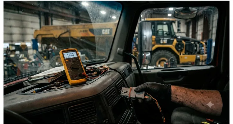
I’ve watched a forty-ton articulated dump truck sit dead in a yard for six days because no one thought to unplug a GPS tracker. You chase intermittent J1939 communication errors for two days, replace a controller, re-pin a connector, and still the network collapses every few hours. Then somebody unplugs one module — maybe that GPS tracker, maybe the secondary display — and suddenly the entire machine comes back to life. No corrupted frames. No random address claim failures. Just a quiet, healthy J1939 bus.
That pattern — swap a controller, still dead, unplug one module and everything wakes up — leaves a specific electrical fingerprint on the bus. I’ll show you exactly which resistance value points straight to a double-termination fault so you recognize it in ten minutes next time. The fix — hunting down a double-termination or a switched terminator — is often absurdly simple once you understand what’s happening electrically. But most troubleshooting guides skip the gritty details that separate a parts-swapper from an engineer who actually fixes things the first time.
Our factory floor in Dongguan ships roughly two hundred thousand J1939 harness assemblies a year. Last March I personally tore down a returned batch because three units out of eight hundred had an intermittent open on pin C — and that teardown is what taught me more about termination than any textbook. We run into double-termination and switched terminator gremlins more often than you’d think, even on brand-new equipment that left another plant with a clean bill of health. My goal here isn’t to hand you a generic checklist. It’s to give you the exact mental model I use when a J1939 bus refuses to cooperate, along with specific measurements, real voltage and resistance values, and the mistakes even good technicians repeat.
When the J1939 Bus Looks Healthy but the Fault Log Says Otherwise
On a heavy-duty machine, the CAN physical layer almost never rats itself out in plain English. You won’t see “check terminating resistor” in the fault codes. You’ll see five ECU’s reporting timeouts, and the natural reaction is to suspect the ECU’s — not the copper between them. Here’s the symptom pattern I’ve learned to recognize:
- Intermittent loss of communication with multiple ECU’s, often random.
- Engine derate or no-start, with diagnostic gauges frozen or flickering.
- Fault codes like J1939-9 (CAN Bus Off), J1939-31 (Network Error), or proprietary timeout codes pointing to the TSC1 or EEC1 message.
- The problem worsens when the machine warms up, or strangely enough, when you close a cab door and flex a harness.
That dump truck from last October arrived at a workshop with no crank, no throttle response, and a CAN error counter climbing faster than the tech could clear it. The engine ECU, transmission controller, and instrument cluster were all logging “timeout” on half a dozen PGN’s. The owner had already swapped the engine ECU with a reman unit — a repair that cost him roughly three thousand two hundred dollars — and the problem returned two days later. When I measured the bus resistance with the batteries disconnected, I saw forty-two ohms instead of sixty ohms.
42 ohms. Right away I knew there was a third 120-ohm resistor hiding somewhere, because two in parallel don’t give you 42. Forty-two ohms isn’t far from sixty, and that’s exactly why double-termination can hide for months. Many transceivers will still push enough differential voltage to communicate on a lightly loaded bus. But as temperature shifts, connector resistance changes slightly, or a specific module sends a dominant bit, the network tips into a recessive-voltage dead zone and one ECU after another drops offline.
Why Double-Termination Isn’t as Rare as Wiring Diagrams Suggest
The J1939 standard mandates a linear bus with exactly two termination points — one at each physical end of the backbone. Each terminator is a 120-ohm resistor, and when the wiring is intact, your multimeter reads sixty ohms between CAN-H and CAN-L with the battery disconnected — the expected parallel resistance defined by the CAN bus physical layer. That’s just two 120-ohm resistors in parallel.
Introduce a third 120-ohm resistor anywhere along the bus, and the parallel resistance drops from sixty to forty ohms. That pulls the recessive differential voltage down toward zero, erodes whatever noise margin you had, and makes the common-mode voltage wander. The CAN transceivers start missing the difference between a dominant bit and a recessive bit. What the software perceives as a timeout is, at the physical layer, a bit that never rose high enough to be sampled.
Double-termination usually comes from one of these scenarios:
- A replacement ECU with an internal terminator enabled when it shouldn’t be.
- A telematics or fleet management device that ships with a default-enabled termination.
- Two pieces of factory-terminated harness joined together during a repair, putting terminators in the middle.
- A “service” terminating resistor plugged into the diagnostic connector and forgotten.
Switched Terminators After a Firmware Update: the 6-Week Intermittent You’ll Never Find by Swapping Parts
A growing number of engine ECU’s and smart displays now hide the 120-ohm termination behind a software checkbox or a set of DIP switches on the circuit board. When a technician flashes firmware, resets parameters to default, or swaps an ECU from one machine variant to another, that switched terminator setting can flip without anyone noticing. I recently traced a six-week intermittent fault on a combine harvester to an engine ECU that had its termination re-enabled during a routine software update at the dealer. The tech had no idea the parameter existed.
We see this trap frequently now that Tier 4 Final and Stage V engine platforms share ECU hardware across multiple vehicle types, each requiring a different bus termination strategy. An engine may leave the factory with termination “ON” if it’s expected to sit at the end of the bus in a tractor, but the same engine installed in a combine with a transmission controller further downstream needs termination “OFF.” The parameter is buried in a service tool menu that many independent workshops can’t access without the dealer software.
When you’re dealing with a machine that has been repowered, or an engine replaced under warranty, always ask: “Did anyone change the CAN termination setting in the ECU?” The answer is almost always a blank stare. Write it into your post-repair validation. Before returning the machine, measure sixty ohms. Not forty-two. Not one hundred twenty. Sixty.
How to Hunt Down an Extra Terminator Without Guessing
I follow a strict electrical approach before I touch a single component. It saves hours and prevents the “shotgun” repairs that make customers lose trust.
Step 1: Isolate the J1939 Bus Electrically
Completely disconnect all batteries — not just the isolator switch. You need zero volts on the bus. If the machine has a battery disconnect, switch it off and then verify with a voltmeter that CAN-H and CAN-L show less than 0.5V to ground.
Step 2: Measure Backbone Resistance First
With everything connected, measure resistance between CAN-H and CAN-L at a convenient access point — the diagnostic connector is usually best, pins C and D on the 9-pin Deutsch. A healthy J1939 backbone reads between fifty-five and sixty-five ohms. Anything reading forty to forty-eight ohms tells you a third terminator is present. If you see one hundred twenty ohms, one terminator is missing or there’s an open circuit. Zero ohms means a short between the lines.
Here’s what I keep taped inside my multimeter lid, because I can never remember the exact numbers when I’m upside down in a cab:
| Measured Resistance (Power Off) | Physical Meaning | Action |
| 60 Ω (±5) | Correct: two 120 Ω terminators | No action |
| 40–48 Ω | Three 120 Ω resistors somewhere | Isolate and find the extra terminator |
| 120 Ω | One terminator missing or open circuit | Locate missing terminator or broken wire |
| 0–2 Ω | Short circuit between CAN-H and CAN-L | Hunt for pinched harness or failed connector |
Step 3: Map the J1939 Nodes, Not Just the Ends
Before you start unplugging anything, realize that the bus rarely runs in a simple daisy chain. Many machines have splice packs tucked inside a frame rail or behind a cab panel. Draw a simple sketch of every device connected to the J1939 backbone — engine, aftertreatment, transmission, ABS, instrument cluster, body controller, telematics, gateway, and any add-ons like a payload monitor or weigh scale. Don’t skip modules that seem “passive”; a GPS tracker can contain a termination.
Step 4: Unplug One Node at a Time and Watch the Resistance
Start with the most suspect — aftermarket devices, telematics, or anything recently replaced. Disconnect the module completely from the bus (not just power). After each disconnection, re-measure the backbone resistance. If the reading stays at forty-two ohms, that module wasn’t the source. Reconnect it before moving on; you don’t want to create open-circuit faults that confuse the reading. When you finally unplug the culprit module and the resistance jumps to sixty ohms, you’ve found the extra terminator.
Step 5: For Switched Terminators, Check the Invisible Settings
If you found the extra terminator inside an engine ECU or display, don’t just remove the physical resistor — you probably can’t. Open the configuration software (like the engine OEM’s service tool) and look under J1939 network settings or CAN settings. A checkbox or drop-down labeled “Bus Termination Enable” or “CAN Termination” is the switch. Deselect it, cycle power, and verify the backbone returns to sixty ohms.
Step 6: If You Find Zero Ohms Instead of Forty
Short circuits are a different beast. Unplug the entire bus from all ECU’s and measure each segment’s CAN-H to CAN-L resistance. A twisted pair worn through inside a bulkhead connector or a pinched harness behind a hydraulic valve is often the culprit. Use a toner or time-domain reflectometer if visibility is poor. One piece of advice: the 9-pin diagnostic connector itself can fail internally, shorting pin C to D. I’ve seen two techs tear apart a cab harness before checking the connector body.
Five Common Mistakes Even Experienced Techs Make
1. Replacing ECU’s Based on Fault Codes Alone
When four different ECU’s report communication timeouts, the problem is rarely inside all four boxes. It’s in the medium they share. Replacing the most expensive unit first is a costly way to learn network diagnostics.
2. Measuring Resistance with the Batteries Connected
A powered bus can give you a resistance reading that looks plausible but is distorted by the transceiver input impedance and common-mode chokes. Always kill power completely.
3. Adding a Terminator to “Strengthen” the Signal
I’ve watched technicians plug a 120-ohm terminator into the diagnostic port hoping to solve poor communication. This just adds a third termination and makes the recessive differential voltage collapse further. It might seem to work for ten minutes, then the bus goes silent.
4. Ignoring the Possibility of a Switched Terminator After a Flash Update
If a machine worked before a dealer software campaign and immediately had CAN faults afterward, check the ECU configuration. It’s more likely than a coincidental wiring failure.
5. Assuming a Brand-New Harness Is Good
We trust new parts because they’re clean and wrapped in loom, but mis-pinned connectors, internal shorts, and backshells that nick insulation are real factory defects. At our facility, every single cable assembly passes a four-step inspection: continuity, hipot, visual under magnification, and a live bus test. Even with that, I still put a meter on the backbone before signing off a repair.
The Moment You Know It’s Fixed
There’s a particular feeling when you disconnect the last suspect module, hear the click of the connector, and watch your Fluke settle on sixty point zero ohms. But don’t stop there. You need to confirm the J1939 bus stays healthy under load.
- Reconnect all modules and measure resistance again with power still disconnected. It should hold at sixty ohms.
- Connect an oscilloscope or a CAN bus analyzer and look at a differential waveform. With both terminators present and the bus idle, you’ll see a clean recessive voltage near zero volts differential, and dominant pulses reaching about two volts with sharp rise times. If the waveform shows sluggish transitions or a recessive level drifting above plus/minus zero point two volts, you might still have a marginal termination or a failing transceiver.
- Clear all fault codes, start the engine, and operate every major function — throttle, transmission range selection, hydraulic demands, and any PTO engagement — while monitoring the bus error counter. A healthy J1939 bus should log zero transmit or receive errors once the network synchronizes.
- Take the machine through a full heat cycle. Run it until the radiator fan cycles at least twice. Double-termination faults love to reappear when harnesses expand and connector contact resistance shifts with temperature.
Document what you found. A simple photo of the multimeter reading with the date and machine hours, saved in the service record, prevents the next technician from starting the same goose chase all over again.
What Belongs in Your J1939 Diagnostic Kit (and What Doesn’t)
You don’t need a dedicated J1939 analyzer that costs ten thousand dollars to find a double-termination fault. A decent digital multimeter with true RMS and a fast continuity buzzer is enough for the resistance checks. But if you do J1939 diagnostics weekly, a few additional tools pay for themselves quickly.
A J1939 breakout box that plugs between the diagnostic connector and your laptop lets you monitor CAN traffic while you move harnesses and connectors. Pair it with a simple CAN-to-USB adapter, and you can see exactly which ECU’s drop offline and which PGN’s disappear. For field work where you can’t carry a laptop, a handheld J1939 diagnostic tester that displays resistance, voltage, and basic network health gives you an answer in seconds.
The cables and harnesses connecting these tools matter just as much as the tools themselves. A poorly shielded diagnostic cable can introduce its own noise and send you down a false path. When you need direct access to CAN-H and CAN-L for a quick resistance check, a 9-pin pigtail breakout cable gives you clean test points without back-probing. If the diagnostic port is buried behind a panel or bracket, a right-angle Y-splitter lets you route the connection into open space. And when you need to bridge from a standard Deutsch 9-pin to a DT 12-pin interface on certain heavy-duty trucks or industrial engines, a 9-pin to DT 12-pin adapter cable removes the frustration of mismatched connectors.
We build J1939 backbone cables, breakout adapters, and diagnostic tees like these in our own facility, and every piece is tested on a live bus before it leaves the calibration bench. If your fleet uses a non-standard connector or needs a custom pinout, our engineering team supports full OEM customization — connector brand, cable length, jacket material, labeling, and even specific color-coding to match your existing harnesses.
When you hold one of our harnesses, the jacket compound was stored in a climate-controlled bay before extrusion — not because a standard requires it, but because we learned the hard way that a nylon jacket that’s absorbed moisture will crack prematurely in a mine. Our facility holds ISO 9001 and ISO 14001 certifications, and our automotive production is audited to IATF 16949. But the real enforcement is the 5S board on the production floor that anyone can mark up if a workstation isn’t right. A terminal connection that fails because a molded strain relief was cured too fast isn’t just annoying; it can strand a machine worth two hundred thousand dollars. Those process details are the only thing between a reliable connection and a field failure.
Questions I Get Asked Most Often
1. What is the correct resistance for a J1939 backbone?
Sixty ohms. That’s two 120-ohm resistors in parallel. I measure it with the batteries disconnected, and I accept anything from 55 to 65 ohms.
2. Can I measure resistance with the battery switch off but batteries still connected?
Better to disconnect the negative battery terminal entirely. Residual voltages from ECU capacitors or keep-alive circuits can skew your resistance measurement.
3. What if I measure one hundred twenty ohms?
One terminating resistor is missing. Possibly a disconnected end device, a broken wire near the end of the backbone, or a terminator that was removed and never reinstalled.
4. Why does the double-termination fault come and go instead of staying permanent?
Thermal expansion, vibration, and humidity alter the contact resistance at connectors and terminators. A bus that reads forty-eight ohms cold might dip to thirty-eight ohms hot, crossing the threshold where the CAN transceivers can no longer compensate.
5. How do I find a switched terminator inside an ECU if I don’t have dealer software?
Physically isolate that ECU by unplugging everything else from the bus and measuring its internal resistance between CAN-H and CAN-L with power off. If you see one hundred twenty ohms, the internal 120-ohm resistor is active. Some ECU’s use a software-controlled relay that stays in its last state even without power, so this measurement can be indicative. The only certain fix is accessing the configuration.
6. Is a double-termination problem the same on J1939 and CANopen?
Electrically, yes — both expect sixty ohms on the backbone. The protocols differ, but the termination physics are identical.
7. Can a bad ground cause termination-like issues?
Yes. If the bus shield or signal ground floats, common-mode voltage can shift and mimic a weak termination. Always verify the shield is terminated to ground at exactly one point, usually near the middle of the backbone.
8. How many terminators is too many?
Exactly two. A third terminator pulls your bus resistance down to forty ohms. Add a fourth, and you’re at thirty ohms — the network will typically go silent.
9. Do all modules on the bus need to be disconnected to test properly?
No, you want all modules connected initially so you see the real resistance. Then you disconnect one at a time to find the extra terminator while watching the meter.
10. We add an aftermarket radio or lighting controller to the J1939 bus — could that cause this?
If the device has an internal 120-ohm termination enabled and it’s not at the very end of the bus, absolutely. Always check the data sheet before plugging anything into the backbone.
Let’s Solve Your Machine’s J1939 Bus Problem Before It Becomes a Breakdown
I’ve written this because I keep seeing the same diagnostic hours burned on a problem that a resistance check and a wiring diagram can solve in twenty minutes. If your fleet, dealership, or repair shop is dealing with stubborn J1939 faults and you suspect a termination issue — or if you need diagnostic cabling that you can trust in a dirty, high-vibration environment — we’re set up for that.
We’re a direct factory with over twenty years of experience building J1939 harnesses, diagnostic adapters, and custom CAN interface cables. Our engineering team regularly helps OEM’s and retrofitters define the right backbone topology, connector pinouts, and termination strategy before production starts. No order is too small for a technical conversation.
- Reach out directly via WhatsApp and share a photo of your multimeter reading or your machine’s diagnostic connector. We’ll help you interpret what you’re seeing.
Chat on WhatsApp - If you prefer email or a detailed RFQ, use our contact page. Tell us about your machine, your bus topology, and what you need customized. We’ll come back with a specific recommendation, not a catalog link.
Contact Our Engineering Team
There’s no shopping cart on this site for a reason. The moment you tell us your machine’s backbone layout and the connector series your engineers chose, we’ll spec the exact AWG, shield type, and pinout — and quote a single production batch, not a per-unit retail price. When you get in touch, you’ll speak directly with someone who understands CAN bus physical layer, not a call center. That’s how we’ve kept mining contractors, bus builders, and engine distributors coming back for over two decades.
