

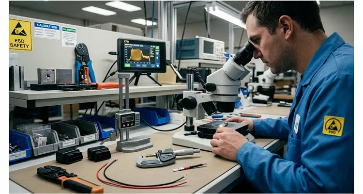
A bench engineer at a Tier 1 diagnostics company once sent me a return: a J1962 extension cable that passed continuity, passed Hi-Pot, and passed visual inspection. The customer’s complaint was intermittent CAN dropouts above 60°C. We cut the overmold open and found the problem in about ninety seconds. The crimp barrel on pin 6 had been compressed to a height 0.12 mm outside the applicator’s process window. At room temperature, the gas-tight connection held. At 60°C, the copper strands relaxed just enough to open a gap of a few microns. Not enough to show on a multimeter. Enough to corrupt a CAN frame.
That is the kind of failure a standard supplier questionnaire will never catch. This article is not a questionnaire. It is a set of seven questions that separate cable assemblers from OBD cable manufacturers, written for engineers who are sourcing custom OBD cables for test benches, diagnostic tools, and OEM programs where an intermittent fault is not an inconvenience. It is a field return.
Why Your Current OBD Cable Supplier Passed the Audit and Still Ships Bad Cables
Short answer: Most supplier audits still check the certificate wall, the lead-time promise, and a golden sample. They do not check whether the crimp process is monitored, whether material changes are validated, or whether a field failure can be traced back to a wire reel. That is why a custom OBD cable supplier can pass an audit and still ship cables that fail after two hundred thermal cycles.
On our own crimp floor, we have watched OBD cable audits focus on the wrong things. Buyers check for ISO certificates, ask about lead times, and request a sample. The sample works. The first production batch works. The third batch ships with a 2% intermittent open rate on the K-line circuit because the supplier changed wire reels without re-validating the crimp applicator.
The root cause is almost never a single defective part. It is a process that cannot detect drift before the drift becomes a defect. In wire harness manufacturing, that means the supplier lacks three things:
- Automated in-process crimp monitoring
- Lot-level material traceability, the kind described in IATF 16949 cable assembly traceability
- A change-management system that treats a new wire reel as a process change, not a purchasing transaction
A cable that passes continuity but fails in the field is not a quality escape. It is a process control escape. The seven questions below are designed to find out whether your supplier controls the process or inspects the product.
Question 1: “Show Me the Crimp Force Monitoring Data for the Last Production Run”
Short answer: A real OBD cable supplier can show CFM data from the last production run. If they only do visual inspection or continuity testing, they cannot detect a crimp that will fail after two hundred thermal cycles.
This is the first question because it immediately separates two categories of supplier.
A manual crimping press produces a mechanical connection. A semi-automatic press equipped with a Crimp Force Monitor (CFM) produces a documented connection. The CFM measures the force applied during every single crimp cycle in milliseconds and compares the force curve against a golden waveform stored in the machine’s controller. If the curve deviates because of a missing strand, trapped insulation, or insufficient compression, the press locks and the operator cannot continue until the fault is cleared.
Ask for the CFM data from a recent production run. A real OBD cable manufacturer will have it. A cable assembler who buys pre-crimped leads and solders them into a connector housing will not.
The engineering reason this matters for OBD cables specifically: pins 4, 5, and 16 carry ground and battery voltage at currents that can exceed 2 A during ECU flashing. A crimp with a 15% reduction in contact area will pass a continuity check and fail after two hundred thermal cycles. CFM is the only in-process method that catches this before the cable is assembled.
What a Real CFM Answer Looks Like
“Our applicator is set to a crimp height of 1.15 mm for the 20 AWG battery circuit, monitored per shift. The last run produced 4,200 crimps with zero CFM rejects. Here is the force curve export.”
What a Deflection Looks Like
“We do visual inspection after crimping.” Visual inspection cannot see a gas-tight connection. It sees whether the terminal looks seated.
Question 2: “What Is Your Traceability Granularity: Lot, Reel, or Individual Cable?”
Short answer: For a J1962 cable used in a diagnostic tool sold to dealerships, traceability should be reel-level. A serial number should map to the wire reel lot, terminal lot, crimp applicator ID, CFM cycle data, and final electrical test record. If the supplier cannot produce all five within one business day, traceability is decorative.
In our experience, traceability is where most supplier audits get polite non-answers. “We have full traceability” means nothing until you define the unit.
For an OBD cable that will be used in a diagnostic tool sold to dealerships, the traceability requirement is typically reel-level. If a batch of 500 cables fails a thermal cycling test, the supplier must be able to identify which wire reels, which terminal lots, and which crimp applicator settings were used for that batch.
This is not an administrative preference. It is the difference between a contained recall and a customer-wide alert.
Ask the supplier to walk you through a mock trace. Pick a finished cable serial number from a recent shipment. Ask them to pull the wire reel lot, the terminal lot, the operator ID, the CFM data from the crimp cycle, and the final electrical test record. If they cannot produce all five within one business day, their traceability is decorative.
Red Flags in OBD Cable Traceability
The supplier can trace the cable to a work order but not to the raw material lots. This means a material defect in one wire reel would require quarantining every cable produced that month.
A Better Engineer-Specific Definition of Reel-Level Traceability
Every cable serial number maps to wire reel lot, terminal lot, crimp applicator ID, CFM cycle ID, and final test record. That is what reel-level traceability looks like on a real work order.
Question 3: “What Is Your Reaction Plan When a CFM or Electrical Test Fails Mid-Run?”
Short answer: A controlled supplier has a written reaction plan linked to the PFMEA. When a CFM fault occurs, the press stops, parts are quarantined, a destructive pull test is performed, root cause is documented, and engineering approval is required before restart. If the operator cannot describe that sequence, the plan is not deployed.
Every supplier will say they “contain” defects. The useful question is what containment actually looks like on the floor.
A controlled process has a written reaction plan linked to the PFMEA. When a CFM fault occurs, the plan specifies: stop the press, quarantine all parts produced since the last verified good part, perform a destructive pull test on a sample from the quarantined lot, document the root cause, and obtain engineering approval before restarting. The plan also specifies who has the authority to restart.
An uncontrolled process has a supervisor who decides whether the fault is “serious enough.”
For OEM programs, this distinction is not optional. IATF 16949 requires a documented reaction plan for every critical characteristic. Crimp height and terminal pull-force are critical characteristics on any OBD cable that carries battery voltage or CAN differential signals. If you also source J1939 harnesses, the same audit logic applies to backbone topology, shield termination, and stub length; the ten questions in J1939 harness supplier qualification cover those physical-layer checks.
The Engineering Test for a Real Reaction Plan
Ask to see the reaction plan for the crimp height characteristic. Then ask the operator on the floor to describe what they would do if the CFM alarm triggered. If the operator’s answer differs from the document, the plan is not deployed.
Question 4: “How Do You Validate a New Wire Reel or a New Terminal Lot Before It Enters Production?”
Short answer: A new wire reel is a process change, not a purchasing transaction. The supplier should quarantine the reel, run a first-article crimp, measure crimp height, perform a destructive pull test, and compare results against the validated process window before production resumes.
This is the question that exposes the difference between a purchasing decision and a process change.
When a supplier receives a new wire reel, even from the same manufacturer and even with the same part number, the insulation diameter and conductor strand count can vary within the manufacturer’s tolerance. Those variations affect crimp compression. A reel with insulation that is 0.05 mm thicker than the validated standard will produce a crimp that passes pull-force testing at the beginning of the reel and fails at the end as the applicator wears.
A controlled supplier treats every new reel as a process change event. The procedure is:
- Quarantine the reel.
- Run a first-article crimp on three samples.
- Measure crimp height with a calibrated micrometer.
- Perform a destructive pull test.
- Compare the results against the validated process window.
Only after engineering sign-off does the reel enter production.
This is also where change management becomes a supplier audit issue. If your supplier can swap a terminal from one manufacturer to another without notifying you, you do not have a controlled supply chain. You have a supplier who will optimize their cost at your program’s risk.
What to Ask for in Reel Validation Records
The last three reel-validation records. If they cannot produce them, they do not have a reel-validation process.
Question 5: “What Environmental Testing Have These Cables Been Subjected To?”
Short answer: An OBD cable lives in the footwell of a vehicle. It sees temperature swings from minus 40°C to plus 85°C, salt spray, humidity, and vibration. Ask for test reports on the exact cable family you are sourcing, not on a similar product from three years ago.
An OBD cable lives in the footwell of a vehicle. It sees temperature swings from minus 40°C on a Minnesota morning to 85°C behind a dashboard in Arizona. It sees salt spray from winter roads. It sees vibration from every pothole. A cable that passes bench testing in a climate-controlled room is not qualified for vehicle service until it survives the environmental envelope.
The relevant tests for OBD cable assemblies are:
| Test | Standard | Typical Condition | What It Catches |
| Thermal cycling | ISO 19642 or customer spec | Minus 40°C to plus 85°C, 100 cycles | Crimp relaxation, insulation cracking |
| Salt spray | ASTM B117 | 5% NaCl, 96 hours, 35°C | Terminal corrosion, plating porosity |
| Vibration | SAE J1455 | Random, 5 to 2000 Hz | Terminal fretting, strain relief failure |
| Humidity cycling | ISO 19642 | 85% RH, temperature swings | Insulation resistance degradation |
| Pull force | UL 486A-B and IPC/WHMA-A-620 | Destructive, 20 AWG approximately 13 lbf minimum | Crimp mechanical integrity |
Ask which of these tests have been performed on the exact cable family you are sourcing, not on a similar product from three years ago. A supplier who has thermal cycling data for a 26 AWG CAN-only cable cannot transfer that data to a 20 AWG battery-circuit cable. The cross-section is different. The crimp window is different.
The Honest Answer From a Real Factory
“We have thermal cycling data for the 20 AWG J1962 assembly. Salt spray testing for OBD harnesses in coastal fleets is performed quarterly on the terminal plating, not on finished cables, because the overmold is the corrosion barrier. Here are the reports.”
The Answer That Should Concern You
“Our materials are RoHS compliant, so environmental testing is not required.”
For OEM programs, a better answer includes the test standard, the exact sample construction, the number of cycles, the pass/fail criteria, and the date of the report. We also provide salt spray testing and PPAP documentation when the program requires it. Jacket material and wall thickness matter too, especially where flex and flame resistance are specified; see UL 94 V0 diagnostic cable jacket thickness and flex.
Question 6: “Who Owns the Test Fixture, and How Is It Calibrated?”
Short answer: A continuity tester that checks opens, shorts, and miswires is the minimum. For a J1962 cable, the fixture should also verify CAN pair resistance balance, insulation resistance between battery and ground pins, and Hi-Pot on battery-voltage circuits. The fixture must have a current calibration certificate.
This question catches suppliers who outsource testing or who use a continuity tester that cannot detect the failure modes that matter.
A continuity tester that checks for opens, shorts, and miswires is the minimum. For an OBD cable, the test fixture should also verify:
- Pin-to-pin resistance on the CAN differential pair, pins 6 and 14. A resistance imbalance above 0.5 ohm between the two lines will degrade signal integrity at high baud rates.
- Insulation resistance between adjacent pins, particularly between pin 16 battery and pins 4 and 5 ground. A leakage path here will drain the vehicle battery through the diagnostic tool, a failure mode explored in moisture ingress and pin-to-pin leakage current.
- Hi-Pot at 500 V DC or higher for any cable that carries battery voltage. A continuity check at 5 V cannot detect insulation breakdown that occurs at 14 V system voltage, which is why continuity and 500 VDC IR testing for CAN bus failures belongs in the fixture specification.
The fixture must be calibrated. Ask for the calibration certificate and the calibration interval. A test fixture that has not been calibrated in two years is not a quality gate. It is a pass-through.
For OEM programs, the test fixture is part of the PPAP submission. If the supplier cannot provide a fixture schematic, a calibration record, and a correlation study between the fixture and the customer’s reference measurement, the PPAP is incomplete.
A Better Engineer-Specific Definition of “100% Tested”
Every J1962 assembly receives continuity, miswire, short, and 500 V DC Hi-Pot; data retained by serial number.
Question 7: “What Happens to My Tooling and Drawings If We Stop Working Together?”
Short answer: For custom overmolds and custom pinouts, the supplier may hold the only molding tools. Ask whether tooling is customer-owned, supplier-owned with a release commitment, or supplier-owned with no release. The answer determines your business continuity risk.
This is not a quality question. It is a business continuity question. It is also the question that reveals whether the supplier sees the relationship as a partnership or as a transaction.
For custom OBD cables, particularly those with overmolded strain reliefs, custom pinouts, or branded connector housings, the supplier may hold the only set of molding tools. If the relationship ends, you need to know what you receive.
A direct factory with more than twenty years of experience will answer this question in one of two ways:
- Tooling is customer-owned. The mold was built with your NRE. You receive the tool, or the supplier retains it with a written commitment to release it upon request.
- Tooling is supplier-owned, but the design is customer-owned. The supplier will not release the physical mold, but will provide the CAD data, the molding parameters, and a qualified second source within a defined transition period.
What you should not accept: “The tooling is ours, and we will discuss it if the situation arises.” That is not an answer. That is leverage.
This question also matters for OEM customization. If your supplier offers logo printing, custom lengths, custom colors, or custom AWG, ask which of those customizations are tied to your tooling and which are standard process changes. A logo printed on the overmold with a pad-print fixture is easy to transfer. A custom connector housing that required a new injection mold is not.
The Four Release Gates on a J1962 Assembly
Short answer: The minimum inspection architecture for a custom OBD cable is four release gates: wire and terminal lot release, CFM crimp control, 100% electrical and Hi-Pot, and serialized final release. A factory that skips the CFM gate and samples the electrical gate will have a defect rate that looks acceptable until field returns arrive.
The seven questions above are diagnostic. This section is the baseline, the minimum inspection architecture a custom OBD cable supplier should have in place before you send them a purchase order.
Gate 1: Wire and Terminal Lot Release
Wire reels, terminals, connector housings, and overmold compounds are inspected against the drawing and the material certificate. Wire is checked for conductor strand count, insulation diameter, and insulation resistance. Terminals are checked for plating thickness and base material. This is not a receiving-clerk function. It is an engineering function.
Gate 2: Crimp Process Control
The crimp press runs with CFM active. The operator performs a pull test at the start of every shift, after every applicator change, and after every new wire reel. Results are recorded in the work order. The test is destructive, and the sample is scrapped, because a pull test that does not break the crimp does not prove the crimp will hold.
Gate 3: 100% Electrical and Hi-Pot
Every finished cable is tested for continuity, miswires, shorts, insulation resistance, and Hi-Pot. There is no sampling. The 100% rule is not a quality preference. It is the only way to catch a miswire that occurred at the end of a production run after the operator’s attention drifted.
Gate 4: Serialized Final Release
Visual inspection under magnification for terminal seating, overmold flash, and strain-relief integrity. Cables are counted, bagged, and labeled with the work order number, the test date, and the operator ID. For OEM shipments, the label also carries the PPAP warrant number.
A factory that follows these four gates will have a defect rate in the parts-per-million range. A factory that skips Gate 2 and samples Gate 3 will have a defect rate that looks acceptable until the field returns arrive.
What IATF 16949 Actually Has to Prove for a J1962 Cable
Short answer: For a Tier 1 diagnostic tool program, IATF 16949 does not just mean the factory has a certificate. It means the supplier can produce a PFMEA for the crimp characteristic, a control plan with crimp height and pull-force limits, and a PPAP Level 3 warrant for the exact cable family. If the supplier cannot show the PFMEA line item for pin 16 battery crimp, the certificate is not doing any work for your program.
Certification is a necessary but insufficient condition. Here is how to read the certificate wall for an OBD cable program.
| Certificate | What it must prove for this cable | Evidence to request | What it does not prove |
| ISO 9001 | A documented quality management system exists | Quality manual, internal audit schedule, corrective action records | That the system is deployed on the crimp floor |
| IATF 16949 | Automotive process control, PPAP capability, PFMEA discipline | PFMEA for the cable family, control plan, PPAP Level 3 warrant, reaction plan | That every OBD cable program is PPAP-managed |
| ISO 14001 | Environmental management system | Environmental policy, waste and chemical records | Product quality or process control |
| RoHS and REACH | Material compliance for restricted substances | Material declarations, test reports from sub-suppliers | Electrical performance or mechanical reliability |
| CE and UL | Market-access compliance for the finished assembly | Declaration of conformity, UL file number where applicable | Crimp quality, traceability, or environmental durability |
The certificate that matters most for an OEM OBD cable program is IATF 16949, because it is the only one that mandates PPAP, FMEA, and a reaction plan tied to process control. ISO 9001 is the foundation. IATF 16949 is the automotive floor. If your supplier holds ISO 9001 but not IATF 16949, they can build a functional cable. They cannot build a PPAP-ready cable for a Tier 1 program.
For non-automotive applications such as test bench harnesses, fleet diagnostic tools, and aftermarket scanners, ISO 9001 plus 100% electrical testing is the practical minimum. For OEM programs, the PPAP level determines the documentation burden. Level 3 is the automotive default: warrant, samples, and full supporting data. The documentation set is similar to what we describe in PPAP Level 3 documentation for OBD cable assemblies.
For a J1962 cable used in a Tier 1 diagnostic tool program, IATF 16949 has to prove something specific. It has to prove the supplier can produce a PFMEA for the crimp characteristic, a control plan with the crimp height and pull-force limits, and a PPAP Level 3 warrant for the exact cable family. If the supplier cannot show you the PFMEA line item for pin 16 battery crimp, the certificate is not doing any work for your program.
A Real Case: The 0.12 mm That Cost a Program Six Weeks
A European diagnostics company was sourcing a custom J1962 extension cable with a 90-degree overmold for a handheld scanner. The supplier was ISO 9001 certified, had a modern facility, and provided a sample that passed every bench test.
Three months into production, field returns began arriving with a specific complaint: “Scanner loses communication when the vehicle interior is hot.” The return rate was 3.2%, high enough to trigger a customer alert, low enough that the supplier initially argued it was within acceptable limits.
We performed a cross-section analysis on six returned cables. Five showed crimp height between 1.08 mm and 1.12 mm, within the supplier’s stated window of 1.05 to 1.15 mm. One showed a crimp height of 1.22 mm, outside the window. That cable had been produced after a wire reel change that the supplier did not validate.
The root cause was not the out-of-spec cable. It was the reel change procedure. The supplier had no procedure. They loaded the new reel, ran a continuity check on three cables, and resumed production.
The fix required the supplier to implement a reel-validation protocol: every new reel gets a first-article crimp, a crimp-height measurement, and a destructive pull test before production resumes. The program lost six weeks to rework and revalidation.
The cost of the reel-validation protocol was approximately two thousand four hundred dollars in engineering time and test equipment. The cost of the field returns was significantly higher, not just the returns themselves, but the customer alert, the engineering investigation, and the confidence lost with the end customer.
The engineering lesson: The failure was not in the cable. It was in the process that allowed a material change to enter production without validation. That process is what the seven questions in this article are designed to audit.
How to Know the Audit Worked: A Post-Audit Verification Protocol
Short answer: An audit is not complete when the supplier answers the questions. It is complete when you verify the answers against evidence. Request CFM data, a traceability mock, environmental reports for the exact construction, and PPAP elements if the program is automotive.
An audit is not complete when the supplier answers the questions. It is complete when you verify the answers against evidence.
Week 1: CFM Data, Traceability Mock, and Reaction Plan
Request the CFM data, the traceability mock, and the reaction plan for the cable family you are sourcing. Give the supplier a deadline. A factory with real process control will produce these in one business day. A factory that is assembling cables from purchased sub-components will need to “check with the production team,” and may not produce them at all.
Week 2: Environmental Test Reports for the Exact Construction
Request the environmental test reports for the specific cable construction. If the supplier has not tested the construction, ask for a test plan and a timeline. A supplier who cannot produce a test plan does not have an environmental qualification process.
Week 3: PPAP Elements for Automotive Programs
Request the PPAP elements if the program is automotive. At minimum: process flow diagram, PFMEA, control plan, dimensional results, and material certificates. If the supplier cannot produce a PFMEA for the cable family, they are not managing process risk.
Ongoing: Change-Notification Clause
Require a change-notification clause in the supply agreement. Any change to wire supplier, terminal supplier, overmold compound, or crimp applicator requires written notification and engineering approval before the change enters production. This is not an unusual requirement. It is the baseline for any automotive supply chain.
FAQ: Custom OBD Cable Sourcing and Supplier Auditing
Q1: How can I tell if my OBD cable supplier actually crimps J1962 terminals in-house?
Ask to see the crimp press, the applicator, and the CFM data from the last production run. An OBD cable manufacturer controls the crimp process, owns or controls the tooling, and can validate material changes. A cable assembler purchases pre-crimped leads or sub-assemblies and solders or inserts them into a connector housing. The assembler cannot control crimp quality because they did not perform the crimp. If they cannot show you the press and the CFM data, they are an assembler.
Q2: Does a custom OBD cable supplier need IATF 16949 for a Tier 1 diagnostic tool program?
For a Tier 1 diagnostic tool program, yes. IATF 16949 is the standard that mandates PPAP, FMEA, and a reaction plan tied to process control. ISO 9001 establishes a quality system. IATF 16949 establishes automotive process control. For non-automotive applications such as test bench cables, fleet tools, and aftermarket scanners, ISO 9001 plus 100% electrical testing is the practical minimum. For OEM programs, commercial vehicles, or any cable installed in a vehicle sold to consumers, IATF 16949 is the required standard.
Q3: Which AWG should J1962 pins 4, 5, 6, 14, and 16 use?
The J1962 connector has 16 pins with different current-carrying requirements. Pins 4, 5, and 16, which carry ground and battery voltage, typically use 20 AWG to minimize voltage drop during ECU flashing. CAN differential pairs, pins 6 and 14, typically use 22 to 24 AWG with twisted-pair construction and a characteristic impedance near 120 ohm. K-line and L-line circuits, pins 7 and 15, typically use 24 to 26 AWG. A supplier who proposes a single wire gauge for all 16 pins is not engineering the cable. They are building a generic harness. For test bench builds where loop resistance and ground separation matter, see test bench OBD cable AWG, loop resistance, and ground separation.
Q4: How do I audit CAN twisted-pair lay length on a custom OBD cable?
Ask for the lay length specification and a sample cross-section. The lay length for an OBD CAN pair is typically 1.5 to 2.0 mm. A supplier who cannot specify the lay length is not controlling the impedance. An untwisted CAN pair will work on a short bench cable and fail intermittently in a vehicle with high EMI. If you are scoping the pair, remember that a 50 MHz scope can miss CAN bus glitches that a higher-bandwidth instrument will show.
Q5: What electrical tests should appear on every J1962 cable test record?
Every J1962 assembly should receive continuity, miswire, short, insulation resistance, and Hi-Pot on battery-voltage circuits. For CAN pins 6 and 14, the record should include pin-to-pin resistance or a resistance balance check. For pin 16 to pins 4 and 5, the record should include insulation resistance. “100% tested” does not mean every cable has been pull-tested. Pull testing is destructive and is performed on samples. If a supplier claims “100% pull-tested,” they are either scrapping every cable or they are not performing a destructive test. Ask them to clarify.
Q6: What is the correct pull-force test frequency for OBD cable crimps?
At minimum: at the start of every shift, after every applicator change or setup, and after every new wire reel is loaded. The test is destructive, and the sample is scrapped. The pull-force value is recorded and compared against the specification. For 20 AWG, the typical minimum is 13 lbf or 58 N per UL 486A-B and IPC/WHMA-A-620. A supplier who performs pull testing once a week is not monitoring tool wear. They are performing a periodic audit, not process control. Crimp resistance drift is a related failure mode; see crimp resistance drift and 3.2 milliohm J1939 ground offset.
Q7: Which PPAP level applies to a custom OBD cable for a Tier 1 program?
PPAP Level 3 is the standard submission for a custom OBD cable program. It includes a Part Submission Warrant, production samples, and the full supporting data package: process flow, PFMEA, control plan, dimensional results, material certifications, and test records. If your supplier is IATF 16949 certified but cannot produce a PPAP for your cable family, they are certified in name only.
Q8: Which ISO 19642 tests matter for a J1962 extension cable?
At minimum: thermal cycling from minus 40°C to plus 85°C for 100 cycles, humidity cycling, and a mechanical pull test on the crimp. For underhood or exposed applications, add salt spray per ASTM B117 for 96 hours and vibration per SAE J1455. The test reports should be for the exact cable construction you are sourcing, not for a similar product from a different program.
Q9: What traceability records should an OBD cable supplier provide in one business day?
A finished cable serial number should map to the wire reel lot, the terminal lot, the operator ID, the CFM data from the crimp cycle, and the final electrical test record. If the supplier can trace the cable to a work order but not to the raw material lots, a material defect in one wire reel would require quarantining every cable produced that month. Traceability is not a negotiable feature. If the supplier cannot produce a mock trace within one business day, treat that as a finding. Either they do not have the data, or they do not want you to see how thin their process control is.
Q10: Why is crimp force monitoring the first thing to audit on an OBD cable supplier?
The crimp process is the one process where a small variation produces an intermittent electrical fault that passes every end-of-line test. Connectors, overmold, and labeling are either purchased from a qualified supplier or are visual characteristics. The crimp is different. A crimp that is 0.12 mm outside the process window can pass continuity, pass Hi-Pot, and fail at 60°C in the field. Ask for the CFM data and the pull-force records. If the supplier cannot produce them, nothing else they show you matters.
Working With a Factory That Expects These Questions
This article is written from the perspective of a factory that has been audited by Tier 1 customers, OEM engineering teams, and third-party quality organizations for more than two decades. The questions above are the ones that separate suppliers who will pass an audit from suppliers who will pass an audit and still ship a bad cable.
The engineering support that makes a difference on custom OBD cable programs is not a sales brochure. It is the ability to take a drawing, a pinout, and a use case and return a DFM review, a crimp specification, and a PPAP-ready process. It is the ability to customize logo, brand, length, color, and AWG without treating each customization as a new program. It is a four-gate inspection process that runs on every order, not just the first article.
If you are auditing a current supplier and the answers to these seven questions are not what you need them to be, the next step is a technical conversation, not a sales conversation. Send the drawing, the pinout, and the failure mode you are trying to prevent. The engineering team will tell you whether the cable can be built to that specification, and what the process control needs to look like to keep it there.
We run CFM-monitored crimping on J1962 assemblies for diagnostic tool programs in Europe and North America. Every cable gets continuity, miswire, short, and 500 V DC Hi-Pot; the test record is stored by serial number. We customize overmold logo, length, color, and AWG from 18 to 26. If you send a drawing and a pinout, the engineering team will return a DFM review and a crimp specification, not a sales deck. For programs that need a longer diagnostic port reach or a clean bench split, we also build the OBD2 extension cable precision diagnostic port reach solution for professional mechanics OEM applications and the universal OBD2 T harness with brackets.
Contact: https://obd-cable.com/contact/
About the Factory Behind This Article
The factory behind this article is a direct manufacturer with more than twenty years of experience in wire harness and OBD cable production. The quality system is registered to ISO 9001, ISO 14001, and IATF 16949, with RoHS, CE, UL, and REACH compliance for applicable products. Production runs under 5S management with a climate-controlled warehouse. Custom OBD cables use RoHS-compliant, full-plastic overmold designs and are 100% electrically tested. OEM customization is available for logo, brand, cable length, color, and AWG. The crimp force monitoring and traceability practices described in this article reflect the process controls required by IATF 16949 and IPC/WHMA-A-620 for automotive cable assemblies.
Standards referenced in this article: ISO 19642, IATF 16949, IPC/WHMA-A-620, UL 486A-B, SAE J1455, and ASTM B117.
