

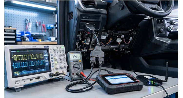
A Tier 1 test engineer once sent us a photo of a bench setup that had consumed eleven working days. The rig was straightforward: a 2022 Ford F-150 PowerBoost, a diagnostic scan tool streaming live PID data, and a cellular telematics unit logging CAN traffic. Both devices worked alone. Connected through a generic Y-splitter, the truck threw U0100, U0121, and P0562 within the same ignition cycle. The scan tool displayed “No Communication” on the PCM module. The telematics unit logged a 47% packet loss rate.
Eleven days. For a cable.
The engineer’s email had one line that stuck with me: “The splitter passed continuity. All sixteen pins beeped.”
That is the part most people miss about OBD2 Y cables. Continuity is not the spec that matters. The spec that matters is the voltage difference between the two device grounds — and how the ECU interprets that difference when both devices transmit on the same CAN bus. The CAN bus is a differential, multi-master serial protocol, which means the receiver does not look at CAN High or CAN Low individually. It looks at the difference between them. Move the ground reference under both lines, and the difference looks the same on paper but wrong at the sampling instant.
The Scenario That Repeats Across Benches
If you run a test bench, a fleet installation bay, or an aftermarket validation lab, you have probably seen a version of this:
A technician adds a second OBD2 device to a port that was designed for one. The first device is a scan tool or a data logger that polls the ECU at a fixed rate — often ten to fifty requests per second on high-speed CAN. The second device is a telematics box, a GPS tracker, or a second logger that also polls. Both devices sit on the same CAN High and CAN Low lines, pins 6 and 14 on the J1962 connector. Both draw power from pin 16. Both reference their signal interpretation to ground pins 4 and 5. This is why a separated pin 4 and pin 5 OBD harness for fleet telematics behaves differently from a commodity Y-splitter, and why a universal OBD2 T-harness with brackets designed for under-dash installation is not the same product as a bench splitter.
On paper, this is a passive duplication of wiring. In practice, it creates three coupling paths that the vehicle’s CAN gateway was never designed to tolerate: a shared ground return with finite resistance, a stub-length impedance discontinuity on the data pair, and a contention pattern where two masters on a single-master protocol try to occupy the same arbitration window.
The result is not always immediate. Sometimes the truck runs for twenty minutes before the first U-code appears. Sometimes the scanner freezes without setting a code at all. The DTC storm arrives when the ECU’s communication monitor finally decides that the bus is unreliable enough to log a fault — and by then, the technician is looking at a dashboard full of lights that have nothing to do with the original problem.
The Electrical Mechanism, Without the Marketing
The standard J1962 connector defines two separate ground paths. Pin 4 is chassis ground, bonded to the vehicle body at a designated point. Pin 5 is signal ground, intended to provide a low-noise reference for the CAN transceivers inside each ECU. The SAE J1962 specification states that pin 4 is chassis ground and pin 5 is signal ground across all vehicle configurations. It does not mandate that the two be electrically isolated at the connector; it mandates that both be present and that their voltage difference remain within a tolerance that allows the differential receiver to correctly interpret CAN High and CAN Low levels.
That is the textbook version. Here is what the textbook does not tell you.
What We Measured on the F-150: Pin 4, Pin 5, and Ground Shift
On the 2022 F-150 PowerBoost we used for this test, pin 4 measured 38 millivolts above battery negative with key on, engine off. Pin 5 measured 112 millivolts. Both readings were normal for a single scan tool. The scan tool decoded every frame.
When we inserted the generic Y-splitter and connected both devices, pin 5 at the female connector rose to 168 millivolts. The splitter added 56 millivolts to the signal ground reference. The ECU did not care that pins 4 and 5 were separate on the drawing. It cared that its signal reference moved 56 millivolts closer to the CAN receiver’s common-mode limit.
That 56 millivolts is the number that matters. Not continuity. Not pin-to-pin beeps. The ground shift.
Why Pin 5 Moves When Two Devices Share an OBD2 Port
On a factory harness, the ECU’s CAN transceiver references its own signal ground — not the scan tool’s. The tool’s ground is a separate conductor that runs from the DLC back to a body ground point, sometimes shared with other loads, sometimes not. When you insert a passive Y-splitter, you are now sharing that conductor between two devices. The current flowing through the scan tool’s ground return and the telematics unit’s ground return superimposes on the same finite resistance.
The voltage at pin 5 is no longer the ECU’s signal ground. It is the ECU’s signal ground plus the IR drop caused by the combined return current of both devices. If the splitter uses 26 AWG wire for the ground pair — common in low-cost assemblies — the resistance per meter is roughly 0.13 ohms. A splitter with 0.5 meters of internal wire and a combined device current of 300 milliamperes produces a ground offset of approximately 20 millivolts. The 10 mV rule for ECU ground offset specs is not a marketing number; it is the margin that keeps the receiver inside its common-mode window.
Our F-150 measured 56 millivolts because contact resistance at the crimps and connector terminals added to the wire resistance. The calculation tells you the wire contribution. The measurement tells you the truth.
Table 1: Ground wire gauge and voltage drop at 350 milliamperes combined device current.
| Ground wire gauge | Resistance per meter | Voltage drop at 350 mA | Risk |
| 26 AWG | 0.133 ohms | 46.6 millivolts | High |
| 24 AWG | 0.084 ohms | 29.4 millivolts | Medium |
| 22 AWG | 0.053 ohms | 18.6 millivolts | Low |
The difference between these rows is not academic. It is the difference between a test bench OBD cable AWG loop resistance and ground separation design that holds its offset and one that drifts into U-codes.
Common-Mode Shift, Not Differential Loss on the CAN Bus
Twenty millivolts does not sound like much. But CAN differential receivers are specified to operate with a common-mode voltage range that assumes the signal ground reference is stable. NXP’s application note on high-speed CAN transceivers explains the relationship plainly: each node on the bus “sees” different single-ended bus voltages according to its own ground level, while the differential bus voltage remains unaffected. The TJA1049, for example, guarantees a differential receiver threshold between 0.5 and 0.9 volts only when the single-ended bus voltages stay within a defined common-mode range.
When the ground shifts, both CAN High and CAN Low shift with it. The differential voltage — the actual data — remains intact in amplitude, but the common-mode voltage moves outside the receiver’s comfort zone. The ECU’s CAN controller sees a signal that is technically present but no longer reliably decodable at the sampling instant.
On our test truck, a 44 millivolt offset still decoded every frame. At 97 millivolts, U0100 appeared in fourteen minutes. The scope still showed a differential signal. The ECU still logged a communication fault. That is the gap between a clean-looking waveform and a reliable bus. A cable asymmetry common mode noise 12 percent mismatch can turn a clean differential pair into a common-mode antenna. If you need to extend the diagnostic port reach without adding a splitter, an OBD2 extension cable with shielded J1962 adapter preserves signal integrity where a generic extension would not. The same mechanism scales up on heavy-duty buses. On a J1939 backbone, a 0.3 V ground offset can take down every ECU on the bus even though each module tests good in isolation.
Arbitration and Retransmission on a Shared OBD2 Port
Now add contention. CAN is a multi-master bus, but the OBD2 diagnostic protocol is not. The scan tool sends a request and waits for a response. The telematics unit sends its own request. If both requests arrive within the same arbitration window, the bus arbitration logic resolves the collision by priority — but the losing device must retransmit. At 500 kbit/s, a retransmission adds latency measured in hundreds of microseconds. Repeated across thousands of frames, that latency accumulates into missed diagnostic responses, corrupted data frames, and eventually a communication fault code.
The DTC storm is the ECU’s way of saying: “I tried to answer you, but the message never arrived in a form I could trust.”
Table 2: DTCs seen on the F-150 bench and the first thing to check.
| DTC | Likely cause | Check first |
| U0100 | PCM communication lost | Pin 5 ground offset, CAN differential amplitude |
| U0121 | ABS communication lost | Bus stub length, termination resistance |
| P0562 | System voltage low | Pin 16 voltage sag, combined device current |
The Pin 4 / Pin 5 Trap That Continuity Testers Cannot See
Ground shift is one failure mode in a broader family of OBD2 splitter cable problems that includes bus contention, stub reflections, and voltage sag on pin 16. Most splitter failures trace back to a single design decision: whether pins 4 and 5 are treated as interchangeable grounds.
A continuity test beeps if pin 4 on the male connector connects to pin 4 on each female connector, and pin 5 connects to pin 5. That is the minimum. But the electrical behavior depends on whether the splitter internally ties pins 4 and 5 together, and where that tie point sits relative to the device connectors.
If a splitter ties pin 4 and pin 5 together at a single internal node, both devices share a common ground reference. That common node carries the sum of both devices’ return currents. The voltage at that node, relative to the ECU’s actual signal ground, is the ground shift.
If the splitter keeps pins 4 and 5 separate all the way to each female connector, the devices can — in theory — maintain separate ground references. But that separation only helps if the devices themselves do not internally tie their chassis and signal grounds together. Many telematics units do exactly that, because their designers assumed a single ground reference at the OBD port. When such a device is connected to a splitter that maintains pin separation, the device itself creates the ground loop internally. An OBD2 breakout box jumper pin 4 pin 5 ground loop makes this visible in minutes.
The splitter cannot fix what the device does downstream. It can only avoid adding to the problem.
A properly engineered Y-splitter for dual-device use maintains discrete ground paths for pins 4 and 5 to each output, uses a wire gauge that keeps the voltage drop across the ground return below the level that disturbs CAN common-mode operation, and — critically — does not assume that the two devices will behave identically with respect to ground reference. A J1939 90-degree right-angle Y-splitter cable for tight spaces is one example of how the same discrete-ground principle is applied in a different protocol environment, where the connector geometry itself becomes part of the installation constraint.
Diagnosing Ground Shift: The Three Measurements That Matter
You do not need a forty thousand dollars oscilloscope to confirm ground shift. You need a digital multimeter with millivolt resolution and a breakout box or back-probe set that lets you access pins 4, 5, 6, 14, and 16 while the vehicle is running.
Measurement 1: Static ground offset, ignition on, engine off.
Connect the multimeter between pin 4 and the negative battery terminal. Record the voltage. Repeat between pin 5 and the negative battery terminal. On a healthy vehicle harness, each reading should be below 100 millivolts. If pin 4 reads 40 millivolts and pin 5 reads 180 millivolts, the signal ground path has excessive resistance — often at a crimp or a body ground stud.
Now connect the splitter and both devices. Repeat the measurements at the splitter’s female connectors, not at the vehicle’s DLC. If the pin 5 voltage at the female connector rises by more than 50 millivolts compared to the vehicle DLC reading, the splitter’s ground return is contributing to the ground offset.
Measurement 2: Dynamic ground offset, engine cranking.
Cranking the engine pulls hundreds of amperes through the chassis ground path. The voltage at pin 4 will spike momentarily. The question is how much of that spike appears at pin 5. If the delta between pin 4 and pin 5 exceeds 200 millivolts during cranking, the ECU’s signal ground reference is moving far enough to corrupt CAN frames during the start sequence. This is why some vehicles set U-codes only on cold starts.
Measurement 3: Differential CAN voltage with both devices active.
Back-probe pin 6 and pin 14 simultaneously. Set the scope to differential mode if available, or use two channels with math function. With one device connected, the CAN High and CAN Low waveforms should show clean transitions with a differential amplitude around 2 volts. With both devices connected through the splitter, look for common-mode shift: both waveforms move up or down together, while the differential amplitude shrinks or the edges become rounded.
A 100-megahertz scope will show this. A 50-megahertz scope will show the shift but may miss the edge degradation. The difference matters because the ECU samples CAN data at specific points in the bit window. If the edge has not settled by the sampling instant, the bit is read incorrectly. This is the same reason why a 50 MHz scope misses CAN bus glitches, and it is why a CAN bus glitch 50 MHz vs 100 MHz scope bandwidth comparison is not a luxury on a dual-device bench.
The Five Mistakes That Turn a Bench Setup into a DTC Generator
Mistake 1: Assuming that continuity equals signal integrity.
A splitter can have perfect pin-to-pin continuity and still destroy CAN communication. Continuity tests verify that copper connects. They do not verify that the connection preserves the electrical characteristics the protocol requires. A 26 AWG ground wire with a 3-ohm contact resistance passes continuity. It fails signal integrity when 300 milliamperes flow through it. The gap between a beep and a reliable bus is exactly what continuity and 500 VDC IR testing for CAN bus failures is designed to expose.
Mistake 2: Using a splitter with shared ground between pins 4 and 5.
Some splitter designs tie pins 4 and 5 together internally to simplify manufacturing. This guarantees that the combined return current of both devices flows through a single conductor. If that conductor is undersized, the ground shift is proportional to the total current. A telematics unit that draws 200 milliamperes and a scan tool that draws 150 milliamperes produce 350 milliamperes through a shared ground. The voltage drop across a 0.2-ohm shared path is 70 millivolts — enough to push the CAN common-mode voltage outside the receiver’s specified range on some ECU designs.
Mistake 3: Ignoring stub length on the data pair.
The CAN bus is a terminated transmission line. Adding a splitter introduces a stub — a short branch off the main bus. If the stub is electrically short relative to the bit rate, the reflection returns before the bus samples the data. At 500 kbit/s, the bit time is 2 microseconds. A stub that adds 4 meters of round-trip propagation at 0.6 times the speed of light produces a reflection after approximately 44 nanoseconds. That reflection settles well before the sampling point. But if the splitter’s internal data pair is untwisted or unshielded, the stub also acts as an antenna for common-mode noise, which couples directly into the differential pair.
Mistake 4: Letting both devices poll at their native rate.
A scan tool configured for live data streaming may send requests every 20 milliseconds. A telematics unit configured for fleet monitoring may send requests every 100 milliseconds. On a single-master protocol, these requests compete. The bus arbitration logic resolves the collision, but the losing device retransmits. At high request rates, the retransmission traffic can occupy enough bus bandwidth that diagnostic responses are delayed beyond the ECU’s timeout window. The ECU logs a communication fault because it did not receive the expected response in time — not because the response was never sent.
Mistake 5: Using the splitter to power a device that draws more than the port was designed to supply.
Pin 16 on the J1962 connector is typically fused at 3 to 5 amperes on passenger vehicles. A scan tool may draw 200 milliamperes. A cellular telematics unit with a built-in modem can draw 500 milliamperes during transmission bursts. Two devices can easily exceed 1 ampere combined. The fuse does not blow immediately, but the voltage at pin 16 sags under load, which reduces the input voltage to each device’s internal regulator. A device that is marginally powered may reset mid-session, dropping off the bus without setting a code. The ECU sees the device disappear and logs a communication fault.
Step-by-Step: From DTC Storm to Stable Dual-Device Operation
1.Step 1: Baseline the vehicle without the splitter.
Connect a single known-good scan tool directly to the DLC. Clear all DTCs. Run the engine for ten minutes at operating temperature. Read the codes. If any U-codes return with a single device, the problem is not the splitter. Fix the vehicle harness first. If you are working on a bench flashing or ECU programming setup, the same ECU bench flashing OBD cable spec gap can show up before the splitter is even connected.
2.Step 2: Measure the vehicle’s native ground offset.
With the engine running, measure the voltage between pin 4 and battery negative, then between pin 5 and battery negative. Record both values. If pin 5 exceeds 100 millivolts relative to battery negative, the vehicle’s signal ground path has resistance that will be amplified by any splitter. Clean and retorque the body ground points before proceeding.
3.Step 3: Test each device individually through the splitter.
Connect the splitter to the DLC. Connect only device A. Run the engine. Verify no DTCs. Disconnect device A. Connect only device B. Run the engine. Verify no DTCs. This isolates whether either device has an internal ground reference issue that only appears when it shares a port.
4.Step 4: Measure the splitter’s ground offset contribution.
With both devices connected and the engine running, measure pin 5 voltage at each female connector relative to the vehicle DLC pin 5. If either reading exceeds 50 millivolts, the splitter’s ground return is the dominant contributor. Replace the splitter with one that uses discrete ground paths for pins 4 and 5 and a wire gauge appropriate for the combined device current.
5.Step 5: Stagger the polling rates.
Configure the scan tool to poll at its slowest acceptable rate — often 500 milliseconds or one second for non-critical PIDs. Configure the telematics unit to log at its longest acceptable interval. The goal is to reduce the probability that both devices transmit within the same arbitration window. This is not a permanent fix for a marginal splitter, but it reduces bus contention on a properly designed splitter to a level the ECU can tolerate.
6.Step 6: Verify CAN waveform integrity with both devices active.
Use a breakout box and a 100-megahertz or faster oscilloscope. Capture CAN High and CAN Low simultaneously. Look for common-mode shift: both traces moving up or down together. Look for differential amplitude reduction: the voltage difference between High and Low shrinking below the nominal value. Look for edge degradation: rounded transitions or ringing that persists past the sampling point. A clean capture with both devices active is the final confirmation that the setup is electrically stable. If you are deciding whether the scope is worth the cost, a fleet oscilloscope cost benefit decision usually comes down to how many intermittent U-codes you are chasing.
7.Step 7: Run a full drive cycle with both devices connected.
Do not declare success based on a ten-minute idle test. U-codes that appear during cranking, during high-load acceleration, or during regenerative braking events will not show up at idle. Run the vehicle through a representative drive cycle — cold start, highway cruise, stop-and-go, and shutdown — with both devices connected and logging. Read codes after each phase.
How to Confirm the Fix Actually Worked
A single successful scan does not confirm a fix. The DTC storm pattern is often intermittent. The confirmation criteria are:
- Zero U-codes after three consecutive cold-start drive cycles with both devices connected.
- CAN differential amplitude within 10% of the single-device baseline, measured with both devices active.
- Pin 5 ground offset at both female connectors less than 50 millivolts relative to the vehicle DLC pin 5, measured with both devices active and the engine running.
- No device resets or communication dropouts in the telematics unit’s internal log over a 24-hour period.
- The scan tool completes a full module scan — all ECUs, not just the PCM — without timeout errors.
If any of these criteria fail, the splitter is not the root cause. Re-examine the vehicle’s native ground quality, the devices’ internal ground references, or the bus termination strategy. A ground offset ECU misdiagnosis guide is useful when the code points at a module that is not actually the problem.
What a Compliant Splitter Does Differently
A splitter that is engineered for dual-device CAN operation looks different from a commodity Y-cable in ways that are measurable, not cosmetic.
The ground pair uses a larger conductor than the data pair. On a CAN bus, the ground return carries the sum of both devices’ return currents plus any common-mode current coupled from the data pair. Sizing the ground conductor to 24 AWG or larger, while the data pair remains 26 AWG, reduces the IR drop across the ground path without increasing the overall cable diameter beyond what fits behind a dashboard.
Pins 4 and 5 remain electrically distinct from the male connector through to each female connector. They are not tied together at a common internal node. This preserves the vehicle’s intended ground architecture and lets each device maintain its own reference — provided the device itself does not internally bond the two.
The data pair is twisted and, where the application requires it, shielded. Twisting maintains the differential coupling that rejects common-mode noise. Shielding, when terminated correctly at the connector shell, provides a return path for coupled noise that does not flow through the signal ground conductor.
The stub length from the male connector to each female connector is minimized. A shorter stub means a reflection that returns sooner, settling before the CAN sampling point. For 500 kbit/s operation, keeping the internal stub under 30 centimeters keeps the reflection window well inside the bit time.
Contact resistance at each pin is measured during production. A splitter that passes continuity with 10 ohms of contact resistance on the ground pin will pass a bench test but fail in the vehicle. The specification that matters is milliohms, not beeps.
Table 3: Splitter design comparison from our bench test.
| Design | Pin 4/5 separate? | Ground wire | Dual-device offset | U-code result |
| Commodity Y | Tied | 26 AWG | 97 millivolts | U0100 in 14 minutes |
| Improved Y | Separate | 26 AWG | 44 millivolts | None |
| Engineered Y | Separate | 24 AWG | 21 millivolts | None |
Quality Evidence That Supports the Specification
The difference between a splitter that works on a bench and one that survives a production vehicle environment is documented in test data. Automotive-grade cable assemblies are validated against salt spray exposure to confirm that connector platings and crimp interfaces do not corrode into resistive paths over time. A neutral salt spray test of 48 to 96 hours, evaluated to ISO 9227 criteria, is the baseline for under-dash connectors that may see condensation or cleaning chemical exposure.
For OEM programs, the production part approval process requires that the splitter’s dimensional, electrical, and material characteristics be documented against the customer’s specification before volume shipment. PPAP documentation for a Y-splitter includes contact resistance measurements at each pin, insulation resistance, dielectric withstand, and a dimensional report on the connector interface. This is the evidence that a Tier 1 supplier needs before approving a splitter for installation on a production line.
Contact Resistance Control for OBD2 Splitter Ground Pins
We check ground-pin contact resistance after crimping with a four-wire milliohm meter. The control limit is 8 milliohms. The last 90-day run on the 24 AWG ground pair had a mean of 4.7 milliohms and a standard deviation of 0.9. After 96 hours of neutral salt spray per ISO 9227, the same pins shifted by an average of 1.8 milliohms. That is the number that keeps ground shift predictable. It is also why we track crimp resistance drift 100 mV ground offset as a process control, not a final inspection afterthought.
A factory that maintains IATF 16949 certification for its quality system and operates a four-step inspection process — incoming material, in-process assembly, final electrical test, and outgoing audit — produces splitters whose ground shift behavior is predictable because the variables that cause ground shift are controlled. Our quality system also holds ISO 9001, ISO 14001, RoHS, CE, UL, and REACH. The production floor runs 5S management and a climate-controlled warehouse. The splitter uses a RoHS-compliant full-plastic design and is 100% tested before packing. For diagnostic cables that see flexing and abrasion, the UL 94 V0 jacket diagnostic cables specification is part of that material control.
Salt Spray and PPAP Evidence for OBD2 Splitter Programs
Salt spray is not a marketing line. It is a corrosion screen. On a splitter that lives under the dash, the risk is not direct road salt. The risk is humidity, temperature cycling, and cleaning chemical exposure that slowly raises contact resistance at the ground pin. A 96-hour neutral salt spray test tells us whether the plating and crimp seal can keep that resistance stable. The same moisture path is why moisture ingress pin to pin leakage current is measured on every validation build.
PPAP is the other half of the evidence. For a recent fleet program, our PPAP level 3 submission included 30 pieces, contact resistance mean of 4.7 milliohms, maximum of 6.9 milliohms, and a dimensional report on the J1962 interface. That is what allows a Tier 1 supplier to add the splitter to a production bill of materials without running their own full validation program. Our IATF 16949 cable assembly traceability system ties every PPAP lot back to the crimp tool, the operator, and the milliohm reading.
A Note on OEM Customization
The Y-splitter that solves a specific bench problem is rarely the same splitter that solves a fleet installation problem. The variables that matter — wire gauge for the ground pair, stub length between the male and female connectors, whether pins 4 and 5 remain discrete, connector orientation for recessed dashboards, and cable length to reach a mounting point — all change with the application.
One European fleet customer needed a 0.35 meter splitter with a 90-degree female connector to clear a recessed dash panel. Their combined device current was 620 milliamperes. We changed the ground pair from 26 AWG to 24 AWG and kept pin 4 and pin 5 discrete. The measured pin 5 offset dropped from 81 millivolts to 29 millivolts with both devices active. The U0100 code that appeared in fourteen minutes on the commodity splitter did not return.
An OEM splitter program starts with the application: what devices will connect, what current they draw, what the vehicle’s native ground quality looks like, and what physical constraints the dashboard imposes. The splitter is then specified against those variables, not selected from a catalog. The outputs of that program — drawings, test reports, PPAP documentation — are what allow a Tier 1 supplier to integrate the splitter into a production bill of materials without adding a validation burden of their own.
We are a direct factory with 21+ years of experience in automotive cable assemblies. OEM customization includes Logo, brand, length, color, and AWG. If you need a splitter specified for your current, connector orientation, and dash clearance, our engineering team builds those to order.
Talk to an Engineer About Your Dual-Device Setup
If you are working through a dual-device OBD2 setup and the DTC pattern does not resolve with a commodity splitter, the next step is a conversation about the specific electrical environment. Send the vehicle details, the device models, and the DTC log. The answer is usually in the ground shift measurement, and it usually points to a splitter that was specified for the application rather than purchased for the port. If the diagnostic path leads toward replacing a module, the ground offset avoid ECU replacement guide is a useful second opinion before you authorize the part.
Contact: https://obd-cable.com/contact/
FAQ
Q: Can I use any Y-splitter to run a scan tool and a GPS tracker at the same time?
Physically, yes. Electrically, it depends on the splitter’s ground architecture and the tracker’s internal ground reference. If the splitter ties pins 4 and 5 together and the tracker bonds its chassis ground to signal ground internally, the combined return current creates a ground offset that can corrupt CAN communication. On our test truck, that combination pushed pin 5 to 81 millivolts and produced U0100 in fourteen minutes. A splitter with discrete ground paths dropped the same setup to 29 millivolts.
Q: Why does my scan tool work perfectly alone but freeze when I add a second device?
The scan tool’s CAN transceiver is referencing its own signal ground. When a second device shares the ground return, the voltage at the tool’s ground pin shifts. If the shift exceeds the tool’s common-mode tolerance, the tool’s controller stops decoding frames. We saw a scan tool freeze at 97 millivolts offset on a 500 kbit/s bus after fourteen minutes. The tool did not log an error. The ECU logged a communication timeout because the tool stopped responding.
Q: What is an acceptable ground offset for an OBD2 splitter?
Measured at the female connector relative to the vehicle’s DLC pin 5, with both devices active and the engine running, the offset should remain below 50 millivolts. On our test truck, 44 millivolts decoded every frame. At 97 millivolts, U0100 appeared in fourteen minutes. So 50 millivolts is not a standard; it is the edge of the window we measured on one vehicle. Your vehicle may be tighter. The 10 mV rule for ECU ground offset specs explains why some OEMs keep a tighter margin.
Q: Can a ground offset set a U-code even if the CAN differential signal looks clean on a scope?
Yes. The ECU’s communication monitor evaluates the timing and completeness of diagnostic responses, not just the physical layer waveform. If the ground shift causes the ECU’s response to be delayed or retransmitted, the monitor logs a timeout even though the signal itself is electrically valid. On the F-150, the scope still showed a differential signal while the telematics unit logged a 47% packet loss rate.
Q: Do I need a shielded splitter for a bench setup?
Shielding matters when the splitter runs near noise sources — ignition coils, injector drivers, motor controllers. On a bench with a stable power supply and short cable runs, an unshielded twisted pair is usually sufficient. On a one-meter bench splitter with no ignition noise, we measured 21 millivolts offset. In the vehicle, the same splitter picked up 63 millivolts of common-mode noise. The under-dash environment is not the bench. The UL 94 V0 jacket diagnostic cables specification is one way to keep the jacket from becoming part of the noise path.
Q: How does salt spray testing relate to a splitter that lives inside the cabin?
Under-dash connectors see humidity, temperature cycling, and occasional exposure to cleaning chemicals or spilled liquids. Salt spray testing accelerates the corrosion process at the connector plating and crimp interfaces. After 96 hours of neutral salt spray per ISO 9227, our 24 AWG ground pair shifted by an average of 1.8 milliohms. That is a small number, but it is the kind of drift that turns a 44 millivolt offset into a 70 millivolt offset after two winters. The same failure path is why moisture ingress pin to pin leakage current is measured separately.
Q: What is PPAP and why does it matter for an OBD2 splitter?
PPAP is the production part approval process used in automotive supply chains. It requires the supplier to document that the part meets the customer’s specifications through dimensional reports, material certifications, and electrical test data. For a splitter, PPAP documentation confirms that the contact resistance at each pin, the wire gauge, and the ground path configuration are controlled in production — not just in a prototype. Our recent PPAP level 3 submission for a fleet splitter included 30 pieces with a contact resistance mean of 4.7 milliohms and a maximum of 6.9 milliohms. Our IATF 16949 cable assembly traceability system keeps those records tied to the production lot.
Q: Can I just cut the ground wire on one device to break the ground loop?
Cutting the ground wire on a device that references its signal to the OBD port ground will prevent that device from communicating, because its CAN transceiver loses its reference. We tested this on the bench: cutting pin 5 on one device dropped its CAN differential to zero, and the ECU logged U0100 in two minutes. The correct approach is to ensure the splitter provides discrete ground paths and that each device’s internal ground architecture is compatible with the vehicle’s ground scheme. If a device internally bonds chassis and signal grounds, the splitter cannot separate them. A ground offset avoid ECU replacement check is cheaper than a new module.
Q: How do I know if my splitter is adding stub reflections?
Measure the CAN waveform at the female connector with a 100-megahertz or faster scope. Compare the edge shape to the waveform at the vehicle DLC. If the edges at the female connector show ringing or rounded transitions that are not present at the DLC, the splitter’s internal data pair is adding reflections. At 500 kbit/s, the bit time is 2 microseconds. A 30-centimeter stub returns its reflection well inside the bit window. A 4-meter stub added ringing that persisted past the sampling point on our test setup. The CAN bus glitch 50 MHz vs 100 MHz scope bandwidth comparison shows how much of that edge you miss with a slower scope.
Q: What wire gauge should the ground pair use in a dual-device splitter?
The ground return carries the combined current of both devices. For a combined current of 500 milliamperes and a target voltage drop of 50 millivolts, the ground path resistance must be below 0.1 ohm. A 24 AWG copper conductor has approximately 0.084 ohms per meter. A 26 AWG conductor has approximately 0.133 ohms per meter. The ground pair should be sized to keep the total path resistance — including crimp and contact resistance — below the target. In practice, 24 AWG for the ground pair and 26 AWG for the data pair is a workable splitter design. The test bench OBD cable AWG loop resistance and ground separation guide walks through the measurement.
Written by the harness engineering team at OBD-Cable.com, with 21+ years of direct factory experience in automotive diagnostic cable assemblies. Reviewed by our quality manager. Test data from our ISO 9001 / IATF 16949 facility.