

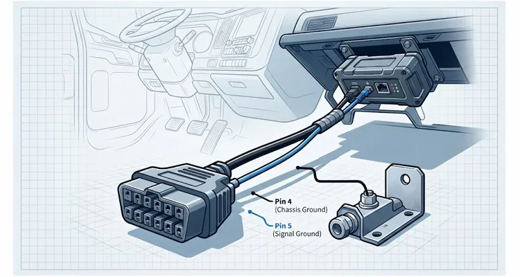
The telematics unit powers up, the status LED blinks normally, but the CAN data stream drops out intermittently—often only when the vehicle is under heavy electrical load. You swap the device, flash new firmware, and check the antenna—yet the problem persists.
The issue is rarely the telematics unit itself. The issue is the wiring convention you are using to interface with the vehicle. Specifically, it is the assumption that Pin 4 (Chassis Ground) and Pin 5 (Signal Ground) on the OBD-II connector are electrically identical. In a modern commercial vehicle, they are not. Tying them together inside a harness is one of the most common root causes of fleet-wide data corruption we see at the factory level.
This article breaks down the electrical engineering behind that failure, why it hits heavy-duty and mixed fleets hardest, and how a separated Pin 4/Pin 5 OBD harness changes the behavior of your installation.
The Physics of the Problem: The Chassis Is Not a Zero-Volt Reference
In a Class 8 truck, the chassis is not a single zero-volt reference. The return current from the alternator—often 200 amps or more—flows through the frame rail, creating a voltage gradient between the engine block and the OBD connector. If you tie Pin 4 to Pin 5, you force the fleet telematics device to reference that moving gradient as its logic ground. This is the same failure mechanism we document in our guide to ground offset and ECU misdiagnosis, where a few millivolts of shift can trigger phantom sensor codes.
Pin 4 is Chassis Ground. It is bonded to the vehicle body, the engine block, and ultimately the negative terminal of the battery. It is the return path for high-current loads: starter motors, glow plugs, electric power steering, air compressors, and in modern electric or hybrid trucks, the high-voltage DC-DC converter.
Pin 5 is Signal Ground. In a properly designed ECU, it is a clean reference plane for the microcontroller and transceivers. It is often isolated from the chassis through the ECU’s internal power supply filtering.
When you bridge Pin 4 and Pin 5 inside an OBD harness, you are forcing the telematics device to use the noisy chassis as its logic reference. You are also providing a path for ground loops.
The voltage difference between the chassis point near the engine and the OBD connector near the dashboard might only be 50 millivolts to 200 millivolts in a diesel truck with the AC on and the trailer lights drawing current. However, a CAN transceiver’s recessive state differential is often only a few hundred millivolts. If your ground reference shifts by 200 mV while the bus is trying to transmit, the receiver can misinterpret a recessive bit as a dominant bit. This results in CRC errors, retransmissions, and eventually, bus-off states. We have measured this exact pattern using a J1939 common-mode voltage shift measurement on a running engine.
Why Mixed Fleets Suffer the Most: Measured Evidence from Real Trucks
A standard passenger car usually has a relatively stable chassis ground. The body is one continuous welded piece of steel; the engine is mounted on rubber, but the ground straps are thick and the loads are moderate. In a commercial fleet, the situation is different.
We measured the resistance from Pin 4 to the battery negative terminal on a 2022 Freightliner Cascadia. It was 0.8 ohms—nearly twice the recommended maximum. On the same truck, the voltage difference between the cab ground stud and the frame rail reached 180 mV with the AC compressor engaged. This is not an isolated case; we have recorded similar values on other body-on-frame vehicles. For a deeper breakdown of how this loop resistance interacts with harness AWG and ground separation, see our test bench OBD cable AWG loop resistance analysis.
Consider a typical Class 8 truck. The cab is mounted on airbags or rubber mounts to isolate vibration. The engine is on a separate subframe. The battery bank is often mounted on the frame rail, far from the dashboard. The OBD connector in the cab might be grounded through a thin 18 AWG wire that runs through three separate harness connectors before reaching the chassis stud.
Meanwhile, the alternator is pushing 200 amps into the battery, and the frame rail is carrying that return current. The potential difference between the frame rail and the cab sheet metal can swing wildly.
If you tie Pin 4 and Pin 5 together at the OBD port, you are not just “grounding” the device—you are connecting the device’s logic ground to a massive antenna that picks up every inductive spike from the alternator, the ABS modulator, and the electric fans.
The Hybrid and Electric Fleet Scenario
In hybrid or battery-electric commercial vehicles, the problem is compounded. These vehicles have high-voltage battery packs (400V to 800V) with isolated grounds for safety. The 12V system is created by a DC-DC converter. This converter generates significant switching noise.
The OBD-II connector in an EV is often required by regulation to be isolated from the high-voltage system, but the chassis ground (Pin 4) may still be referenced to the vehicle body, which acts as a shield but not necessarily a clean signal return. A short between Pin 4 and Pin 5 can inject common-mode noise directly into the telematics device, causing the microcontroller to reset or latch up. This is the same failure mode we explore in common-mode voltage on J1939 killing communication.
The Specific Failure Mode: How a Bridged Ground Kills Your Data
Moving from theory to field symptoms, here is what you will encounter when you use a standard “combined ground” OBD cable. You are creating a specific set of failure signatures that are difficult to diagnose remotely.
Intermittent CAN Bus “Wake-Up” Failures
Many telematics devices use a sleep mode to conserve vehicle battery. They wake up when they see activity on the CAN bus or a voltage change on a specific pin. If the ground reference is unstable, the wake-up comparator may miss the voltage transition because the “zero” it is comparing against is shifting. The device stays asleep while the vehicle is driving. You lose an entire trip of data.
Unexpected DTCs That Disappear When the Telematics Harness Is Unplugged
It is not just the telematics device that suffers. By bridging Pin 4 and Pin 5, you are effectively shorting the ECU’s signal ground to the chassis at an unapproved node. This can introduce a ground loop current into the ECU’s sensor circuits.
A fleet operator reported a P0118 (Engine Coolant Temperature Circuit High) code on three trucks. The dealer replaced the sensor twice. The code only appeared when the telematics device was installed. Once we swapped to a separated harness, the code did not return in six months of operation. This is a classic case of what we describe in how to avoid ECU replacement from ground offset: the dealer was chasing a sensor fault when the real problem was a two-millivolt shift on the signal ground.
The mechanism is straightforward: if the telematics device has a slightly different potential on its own internal ground plane (due to its power supply), current will flow from Pin 5 through the device and out to the chassis via Pin 4. This current can be tiny—microamps—but it flows through the traces on the ECU board. This can skew analog sensor readings by a few millivolts, leading to intermittent fault codes that the dealer can never reproduce because the telematics harness is not installed when the dealer inspects the vehicle.
Premature Hardware Failure
At the component level, the transceiver is not the only victim. The power supply in the telematics device is usually a buck converter that references the input ground. A noisy ground translates to noise on the 3.3V or 5V rail. This stresses the electrolytic capacitors and can degrade the flash memory over time. We have seen fleets where devices last three years in passenger cars but only nine months in heavy trucks purely due to ground noise.
The Engineering Solution: A Separated Pin 4/Pin 5 Harness
A separated harness is not a different product category; it is a change in the wiring schematic inside the cable. A standard harness physically connects Pin 4 and Pin 5 together at the OBD connector (or inside the overmold). A separated harness runs two distinct wires from the OBD connector to the telematics device.
Inside the Device:
- Pin 5 (Signal Ground) connects directly to the device’s main logic ground plane. This is the reference for the CAN transceiver, the microcontroller, and the analog front-end.
- Pin 4 (Chassis Ground) connects only to the device’s shield and the metal connector shell. It is the safety ground and the ESD discharge path.
The Critical Detail: The Device Must Support It
Not every telematics device exposes Pin 4 and Pin 5 on separate pins at its own connector. Many consumer-grade OBD dongles tie them together inside the plastic housing. If your device does this, a separated harness will not help because the short is inside the device.
One OEM wired Pin 4 to the logic ground plane and Pin 5 to the shield on their prototype. The result was that every ESD strike on the connector shell went directly into the microcontroller’s ground, causing random resets during dry winter months. That mistake was caught in the pilot phase, but it illustrates why the device schematic matters as much as the harness. A related issue shows up in crimp resistance drift and 100 mV ground offset, where a single bad crimp on Pin 4 can mimic a device-level ground fault.
If you are using a professional fleet telematics unit with a multi-pin connector (Deutsch, Molex, or a custom pin header), you have the ability to route the grounds correctly. This is where working with a factory that understands harness engineering matters. A harness is not just “wires with a plug.” It is a component that must match the impedance, shielding, and grounding architecture of both the vehicle and the device.
Step-by-Step: How We Build a Separated Harness for Fleets
When a fleet manager or a telematics hardware vendor approaches us with a data integrity problem, we usually follow this diagnostic and manufacturing process.
Step 1: Determine the Device’s Ground Topology
The first question we ask is: “On your device’s connector, is Pin 5 isolated from the metal shell?” If the answer is no, you need to fix the device first. If the answer is yes, we proceed. We also ask for the device’s schematic to confirm that Pin 4 and Pin 5 are not tied together on the PCB. This step is critical because a device that shorts the grounds internally cannot be fixed by any harness—a fact we cover in our OBD2 breakout box jumper Pin 4/Pin 5 ground loop guide.
Step 2: Wire the OBD Connector Correctly
We use a standard OBD-II male connector. Pin 4 is wired with a dedicated conductor—often 20 AWG or 22 AWG depending on the current requirement for ESD discharge—to the device’s chassis ground input. Pin 5 is wired with a separate conductor, often 22 AWG twisted with the CAN High and CAN Low lines, to the device’s logic ground.
Step 3: Cable Shielding Strategy
If the harness is longer than one meter (which is common for fleet installations where the device is mounted under the dash or behind a panel), we recommend a shielded cable. The shield drain wire is connected to Pin 4 (Chassis Ground) at the OBD side only. This prevents the shield from becoming a ground loop path while still providing ESD protection.
We learned the hard way that connecting the shield drain to Pin 5 on the OBD side creates a secondary ground loop through the device’s chassis. That mistake caused a 30% increase in CAN error frames on a fleet of electric delivery vans. The shield should only be tied to chassis ground at one end, never to signal ground. For a deeper look at how shield termination interacts with moisture and pin-to-pin leakage, refer to moisture ingress and pin-to-pin leakage current.
Step 4: Overmold and Strain Relief
The failure point in most fleet harnesses is the connector overmold. If the mold is too soft, the wires flex and break. If it is too hard, it transmits vibration to the solder joints. We use a two-shot injection molding process with a soft inner core and a rigid outer shell. This is a detail that is invisible to the user but determines whether the harness lasts five years or five months.
Verification: How to Confirm the Fix Works in the Field
You cannot just install a separated harness and assume the problem is solved. You need to verify it with the right equipment.
The Oscilloscope Test
Connect a differential probe to CAN High and CAN Low at the telematics device’s connector. Trigger on a recessive bit. Look at the baseline differential voltage. Then, switch on the vehicle’s heavy loads: headlights, AC, wipers, and if possible, engage the starter or the electric power steering. For a step-by-step guide on capturing these waveforms, see reading J1939 waveforms like a pro.
With a combined ground harness, you will often see the baseline shift or see bursts of high-frequency noise superimposed on the differential signal. With a separated harness, the baseline should remain stable. The differential signal should stay within the ISO 11898-2 limits even during load transients.
The Ground Current Test
Place a current clamp around the Pin 4 wire alone. With the vehicle running and loads on, measure the current. On a healthy separated harness, the current on Pin 4 should be below 50 microamps. We once measured 3.2 milliamps on a truck with a defective DC-DC converter—the current was flowing from the chassis into the device’s logic ground through the shield. That truck logged 14 bus-off events in one week.
If you see milliamps of current flowing on Pin 4, you have a ground loop somewhere else in the system, and the harness is doing its job by providing a separate path instead of forcing that current through the device’s logic ground.
The Long-Term Data Test
Deploy ten vehicles with the standard harness and ten vehicles with the separated harness. Log the CAN error counters over a month. The separated harness group should show a significant reduction in bus-off events and retransmissions. This is the data point that justifies the engineering change to your management.
Common Mistakes When Ordering a “Separated” Harness
Over the years, we have seen many specification documents that say “Pin 4 and Pin 5 separated” but fail to address the actual performance requirements. Here are the mistakes that keep coming back.
Mistake 1: The Harness Is Separated, but the Device Shorts Them Anyway
This is the most common. The telematics vendor orders a separated harness, but their own PCB connects the ground pins. The harness is correct; the system is still wrong. Always check the device schematic before specifying the harness.
Mistake 2: Wrong Wire Gauge
Pin 4 is not just a signal wire; it is a safety ground. If there is a fault inside the device, current must flow through Pin 4 to the chassis and blow a fuse or trip a protection circuit. If you use a 26 AWG wire for Pin 4, it will melt before the fuse blows. The wire becomes the fuse. For chassis ground, we never go below 20 AWG for a one-meter harness.
Mistake 3: Ignoring the Vehicle’s Own Wiring
If the vehicle’s OBD connector has a corroded or undersized chassis ground wire, a separated harness will not fix the vehicle’s problem. In a fleet, you should check the resistance from Pin 4 to the battery negative terminal. If it is more than 0.5 ohms, fix the vehicle first. We have seen fleets where half the trucks had chassis ground resistances above 0.7 ohms due to corroded bolts. This ties directly into our continuity 500VDC IR testing for CAN bus failures procedure, which catches exactly these high-resistance chassis bonds.
Mistake 4: Using an Unshielded Twisted Pair for CAN
Even with perfect grounds, an unshielded cable in a noisy environment (near the engine ECU or the alternator) will pick up radiated noise. A separated harness should still use a shielded twisted pair for CAN High and CAN Low, with the shield tied to chassis ground at one end only.
The Factory Perspective: Why This Harness Is Not a Commodity
Most OBD cables on the market are built to a price point for consumer dongles. They are designed to work in a 2015 Toyota Camry, not in a 2024 Freightliner Cascadia with a Detroit DD15 engine and an electric APU. When you are deploying telematics across a thousand trucks, the harness is the cheapest part of the system, but it is the part that determines whether the other nine hundred dollars of hardware actually works.
Our production line runs 16 hours a day, six days a week, building custom harnesses. Last year we shipped 340,000 units to North America, 60% of which were for commercial vehicle telematics. We build separated harnesses for fleet telematics vendors, not as a generic product, but as an engineered component. The process includes:
- Schematic Review: We look at your device’s connector pinout and ground topology before quoting anything. If your device has a design issue, we will tell you before we build a thousand cables that do not work.
- Cable Selection: We specify the conductor gauge, insulation material (XLPE for high-temperature engine bays, PVC for interior), and shielding based on the vehicle environment. For electric vehicles, we often use a foil-and-braid double shield because the switching frequencies from the inverter are higher.
- Connector Molding: We use a two-shot overmold process to eliminate water ingress at the connector backshell. This is a common failure point in trucks that run through car washes or in coastal fleets with salt spray.
- 100% Testing: Every separated harness is continuity-tested to verify that Pin 4 and Pin 5 are not shorted together, and that the shield is connected to Pin 4 only. We also perform a hipot test to ensure no leakage between the chassis ground and the signal lines.
The Role of Standards and Traceability
For fleet hardware vendors selling into the North American or European market, traceability matters. A harness that fails in the field can cause a truck to be down for a day. The cost of that downtime is far higher than the cost of the cable.
During a recent IATF 16949 audit, we had to demonstrate traceability for a batch of 2,000 separated harnesses shipped to a European fleet operator. The auditor pulled lot 2024-08-12 and asked for the raw material certificates for the XLPE insulation. We provided them in under ten minutes because our ERP system links every production order to incoming inspection records. That is what the certification means in practice—not a wall plaque. You can read more about our IATF 16949:2016 certification milestone and our ISO 14001:2015 environmental management commitment.
We also maintain environmental compliance. All cables meet RoHS and REACH standards. For fleets operating in California or the EU, this is not optional—it is a legal requirement. We test for restricted substances at the raw material level, not just the finished product.
The factory itself operates under 5S management and climate-controlled storage. A cable that sits in a humid warehouse for six months before shipping will have oxidized copper conductors. Oxidation increases resistance and reduces the cable’s ability to handle surge currents. We store finished goods in a controlled environment to prevent this.
When Do You Actually Need This Harness?
A separated harness is unnecessary for a rental car GPS tracker. The electrical environment is too benign to justify the engineering overhead. But you need a separated harness when:
- The vehicle has a body-on-frame construction. This includes most pickup trucks, vans, and Class 3-8 commercial vehicles.
- The vehicle has a high-current electrical system. This includes diesel engines with glow plugs, electric power steering, electric air conditioning, or any vehicle with an aftermarket inverter for tools or refrigeration.
- The telematics device has an analog input. If you are reading fuel level, temperature, or pressure sensors directly from the vehicle’s analog wiring, a clean signal ground is mandatory. The offset introduced by a ground loop can be larger than the sensor’s full-scale output.
- The device has a sleep mode with wake-on-CAN. As described earlier, the wake-up circuit depends on a stable reference.
- You are deploying in electric or hybrid vehicles. The switching noise from the DC-DC converter is a known killer of poorly grounded electronics.
If none of these apply, a standard harness is fine. If any of them apply, you are not saving money by using a cheap cable. You are shifting the cost to your field service team and your customer support line.
Related Products and Custom Engineering Support
The separated Pin 4/Pin 5 harness is not a single SKU. It is a configuration that can be applied to different connector types, cable lengths, and pinouts. The most common configurations we build for fleet customers are:
- OBD-II Male to Flying Leads: For devices that use a terminal block or a soldered connection inside an enclosure.
- OBD-II Male to Deutsch DT Series: For ruggedized installations in engine bays or under-chassis mounting.
- OBD-II Male to Molex Micro-Fit: For compact devices with limited internal space.
- OBD-II Male to Custom Keyed Connector: For OEM telematics vendors who need to prevent technicians from plugging in the wrong harness.
We also support OEM customization on the physical branding level. If you are a telematics vendor selling to a fleet operator, you may want your logo on the overmold, a specific cable color (e.g., blue for EV fleets, black for standard), or a specific wire gauge. We handle these as standard options, not as special projects.
The minimum order quantity for a custom separated harness is lower than you might expect because we run these cables on a dedicated production line. We are not a distributor that buys pre-made cables from a catalog; we are the factory that cuts, strips, crimps, and molds the cable in-house.
Frequently Asked Questions (FAQ)
1. I cut the trace on a prototype device to separate the grounds, and it passed FCC testing. Why is that a bad idea?
Because the production device will have a different PCB layout. The trace you cut on the prototype might not exist on the production board. We have seen a vendor ship 500 units with the trace intact because the factory used a different Gerber file. The FCC certification applies only to the exact configuration tested. A production unit with the trace intact is a different device, and you are now operating uncertified hardware in the field.
2. My device only has one ground pin. Can I still use a separated harness?
No. If the device has only one ground input, Pin 4 and Pin 5 are shorted inside the device. A separated harness will not solve that problem. You need a device with separate chassis and signal ground inputs, or you need to redesign the device. There is no cable workaround for a single-ground-pin design.
3. Is a separated harness more expensive?
The cost difference is minimal at the factory level—often a few cents per unit in materials. The main cost driver is the engineering time to verify the wiring and the testing to ensure the separation is maintained. For a fleet deployment, this is negligible compared to the cost of a single truck roll, which can exceed seven hundred dollars in labor and downtime.
4. Does a separated harness work with J1939 (heavy-duty CAN)?
Yes. J1939 uses the same physical layer as CAN 2.0B, but the data rate is 250 kbps. The noise immunity requirements are actually higher because the bus is longer and the environment is harsher. A separated harness is even more critical for J1939 than for ISO 15765 (passenger car CAN). For a practical diagnostic approach, see J1939 physical layer multimeter diagnostics.
5. Can I use a separated harness with a single-wire CAN (SWC) vehicle?
Single-wire CAN (GM’s old J2411) is a different animal. It uses the chassis as the return path by design. A separated harness will not work with SWC because there is no differential pair. You need a specific SWC interface. Most modern fleets have moved to high-speed CAN, so this is rarely an issue.
6. What length can I run a separated harness?
For high-speed CAN, the maximum bus length is 40 meters at 1 Mbps, but that is for the entire bus, not just your harness. In practice, you should keep the telematics harness under 3 meters. Beyond that, you need to consider termination and cable capacitance. We build harnesses up to 5 meters for specific installations, but we always test them with the actual device before approving the design.
7. My device uses an OBD splitter cable (Y-cable). Should I use a separated harness on both branches?
If the splitter is passive, the ground separation must be maintained on the branch that goes to the telematics device. The other branch goes to the original vehicle diagnostic port or another accessory. You should avoid using a passive splitter that ties the grounds together at the split point, because that defeats the purpose.
8. How do I know if my current harness is causing data errors?
Record the CAN error counters from your device’s diagnostic interface. If you see a high number of “receive error” or “transmit error” frames that correlate with vehicle operation (high RPM, heavy electrical load), and the errors disappear when the vehicle is idling with no accessories on, you have a strong suspect. Swap the harness for a separated one and see if the error count drops. In one fleet, the error count dropped by 82% within the first week.
9. Does a separated harness affect the OBD-II pin for battery voltage (Pin 16)?
No. Pin 16 is the battery positive supply. It is independent of Pin 4 and Pin 5. However, the ground reference for measuring the battery voltage is Pin 5. If Pin 5 is noisy, your voltage readings will be noisy. A separated harness gives you a cleaner voltage measurement.
10. Can I order a sample separated harness before committing to a full production run?
Yes. We always recommend building a small pilot batch—ten to twenty units—and testing them in the actual fleet vehicles for at least two weeks before moving to volume production. This catches any vehicle-specific quirks that are not visible on the bench. We support this pilot process as part of our standard workflow.
Next Steps: Getting the Harness Right the First Time
If you are responsible for fleet telematics hardware and you are seeing unexplained data errors, device resets, or early hardware failures, the ground topology is the first thing to check. The fix is often simpler than you think: separate Pin 4 and Pin 5, route the shield correctly, and verify the device’s internal grounding.
Our factory has been building custom wiring harnesses for industrial and automotive applications for over twenty years. Last year alone we shipped 340,000 units to North America, and we have supported fleets ranging from regional delivery vans to long-haul Class 8 trucks. We can review your device schematic, recommend the right cable construction, and build a separated harness that meets your exact pinout and length requirements.
For OEM customization—logo, branding, cable color, wire gauge, or connector type—we handle the full process from drawing to production. We do not sell from stock; we build to your specification.
If you need engineering support on a separated Pin 4/Pin 5 harness for your fleet telematics installation, you can reach us through the contact page on our website. We usually respond within one business day with technical questions, not a sales pitch. Or, if you prefer to discuss your application directly, you can reach our engineering team via WhatsApp using the link below.
Contact Page: obd-cable.com/contact/
WhatsApp (Direct line to our engineering support): Chat with Linda on WhatsApp
Tell us what vehicle platforms you are deploying on, what device you are using, and what symptoms you are seeing. We will help you determine if a separated harness is the right fix and provide a drawing for your review before anything is built.
