

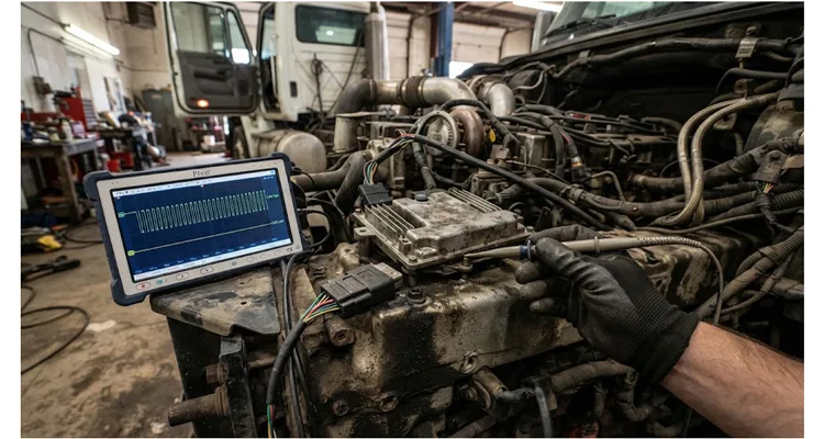
The key tag had three repair orders stapled to it. A 2019 Peterbilt 579 with a PACCAR MX-13 had already received an engine ECM, an aftertreatment controller, and two backbone harness sections. The driver’s complaint was specific: derate at 45-minute intervals, always after coolant temperature stabilized above 185°F. The shop had twelve hours of diagnostic labor in it and no fix. When I connected a PicoScope to the diagnostic connector, the answer was on the screen: 0.31 volts of DC offset between the engine ECM’s ground reference and the cab controller’s ground reference. That tiny voltage—less than a third of what a AA battery produces—was blinding every ECU on the backbone.
No module on that truck had failed. Every terminating resistor measured 120 ohms. The multimeter said everything was fine. The bus was still dead. That contradiction is what turns a cheap ground fault into an expensive diagnostic event: the standard tests pass, the parts cannon gets loaded, and the real fault stays hidden in the ground path.
Where a 0.3V Ground Offset Actually Comes From
SAE J1939-11 specifies a maximum allowable ground offset of two volts between any two ECUs on the bus. At first glance, 0.3 volts seems insignificant—barely 15% of the allowable limit. But the specification describes a steady-state condition with a properly terminated bus and all ECUs operating within their designed common-mode range. A test bench does not heat-soak a chassis, cycle a fan clutch, or push 200 amps through a corroded crimp.
The Peterbilt That Came Back Three Times
The offset I measured on that Peterbilt did not exist at key-on. It appeared only when the engine coolant temperature exceeded 185°F and the radiator fan clutch engaged. When that 40-amp load kicked in, the engine block’s ground potential shifted by roughly 0.3 volts relative to the cab. The engine-to-frame ground strap—a braided cable roughly the diameter of a pencil—had corroded internally. From the outside, the cable looked fine. No green crust, no visible damage. Inside the crimp, the copper had oxidized to the point where the strap’s resistance had climbed to 0.18 ohms. At 40 amps, Ohm’s law gives you 7.2 volts of drop. The chassis wiring absorbed most of it, but 0.3 volts leaked through to the ECM ground reference.
The failure mechanism is current-dependent. A ground path that measures 0.05 ohms with a multimeter can rise to 0.5 ohms under thermal cycling, vibration, and electrical load. The multimeter test you did in the shop at 70°F tells you nothing about what happens when the engine is at operating temperature and the alternator is pushing 200 amps into a weak battery. That is why a dynamic ground offset can pass every static check and still kill J1939 communication on the road.
The Physics Behind the 0.3V Number
A CAN transceiver interprets the bus by comparing the voltage difference between CAN_H and CAN_L. In the recessive state, both lines sit at approximately 2.5 volts, giving a differential of zero. In the dominant state, CAN_H pulls to about 3.5 volts and CAN_L drops to about 1.5 volts, producing a two-volt differential. The transceiver does not care about absolute voltage—it only looks at the difference. Texas Instruments covers this differential signaling architecture in detail in its CAN physical layer training series.
But that is the simplified model. Real transceivers have a finite common-mode rejection ratio. When the ground reference at one ECU differs from the ground reference at another by 0.3 volts, the differential signal gets biased. A dominant bit that should produce a two-volt differential might appear as 1.7 volts on the receiving end. Still detectable. But add electrical noise from an injector driver or a PWM-controlled fan, and that 0.3-volt offset becomes the tipping point where the receiver starts misinterpreting bits.
The SAE standard defines the common-mode voltage range as -2.0 volts to +7.0 volts on CAN_H, and 1.2 volts to 5.0 volts on CAN_L, measured relative to each ECU’s own ground. A 0.3-volt ground offset eats directly into that margin. It does not cause immediate failure. It causes intermittent failure—the kind that disappears the moment you connect a diagnostic tool and reappears when the customer drives away.
The Diagnostic Trap That Costs Thousands
Standard J1939 troubleshooting procedures tell you to check resistance between pins C and D at the diagnostic connector. A healthy network reads 60 ohms. If you read 120 ohms, one terminating resistor is missing. If you read infinity, the backbone is open. Both are required, but neither one is sufficient.
Why the 60-Ohm Test Is Necessary but Not Enough
The 60-ohm test confirms both 120-ohm terminators are present and the backbone is not open. But it says nothing about whether the engine ECM’s ground reference matches the cab controller’s ground reference when the radiator fan clutch engages and pulls 40 amps. That is a different test, and it is the one most technicians skip.
The resistance test tells you about the terminating resistors. It tells you nothing about ground integrity. It tells you nothing about shield termination. It tells you nothing about the dynamic behavior of the ground path under load. A J1939 backbone can pass the 60-ohm test and still be incapable of reliable communication once the alternator, fan clutch, and injectors start switching current through the chassis.
What the Voltage Test Misses
The voltage test is slightly better. With the key on and engine off, you should read approximately 2.6 volts on CAN_H and 2.3 volts on CAN_L, both measured relative to pin A, battery negative, at the diagnostic connector. A healthy backbone will show these values within ±0.1 volts. But those measurements are taken at a single point in the network. They tell you what the bus looks like at the diagnostic connector, not what it looks like at the engine ECM, which might be 15 feet of wire and three connectors away.
The 0.3-volt offset I found on that Peterbilt was invisible at the diagnostic connector. At that point, CAN_H read 2.58 volts and CAN_L read 2.31 volts. Both within spec. The offset only became visible when I measured CAN_H and CAN_L at the engine ECM connector relative to the engine block, and simultaneously at the cab controller connector relative to the cab ground. The difference between those two reference points was the killer. To reach both measurement points cleanly without piercing insulation, I used a J1939 9-pin breakout cable at the diagnostic port and a J1939 9-pin to DT 12-pin adapter at the engine harness side.
A Step-by-Step Protocol for Catching What the Multimeter Misses
What follows is the diagnostic sequence I have refined over twenty-plus years of building J1939 harnesses and diagnostic cables for OEMs. It is the same procedure our factory uses when a customer returns a harness with a “no communication” complaint that our incoming inspection could not reproduce.
Step 1: Establish a Baseline with the Engine Cold
Key on, engine off. Measure voltage at the diagnostic connector between pin A, battery negative, and pin C, CAN_H. Record the value. Measure between pin A and pin D, CAN_L. Record the value. A healthy bus gives you CAN_H = 2.6V ±0.1V and CAN_L = 2.3V ±0.1V. If you are outside that window, stop here and diagnose the static fault first.
Step 2: Load the Ground Path
Start the engine. Turn on every electrical load you can: headlights, HVAC blower on high, seat heater, air horn. If the truck has a PTO, engage it. If it has a hydraulic system, deadhead a cylinder. The goal is to maximize current flow through the chassis and engine ground paths. Wait for the cooling fan to cycle at least once. This is where the dynamic ground offset reveals itself.
Step 3: Measure the Offset Directly
This is the critical step that most technicians skip. You need to measure the voltage difference between the ground reference at one ECU and the ground reference at another ECU while the bus is active.
Set your DMM to DC volts. Place the black lead on the engine ECM’s ground pin, or the engine block itself as close to the ECM mounting point as possible. Place the red lead on the cab controller’s ground pin, or a known good cab ground. Read the voltage. Then reverse the leads and read again. The magnitude of the larger reading is your ground offset.
On the Peterbilt, I measured 0.31 volts with the fan running. With the fan off, the offset dropped to 0.04 volts—essentially zero. That 0.27-volt swing under load was the entire root cause of twelve hours of misdiagnosis.
Step 4: Confirm with a Scope
A multimeter gives you the DC component. A scope shows you what is happening at the bit level. Connect Channel A to CAN_H and Channel B to CAN_L, both referenced to battery negative. Set the timebase to 100 microseconds per division and the voltage scale to one volt per division. You should see a clean differential square wave with a dominant-state differential of approximately two volts. Pico Technology’s Scope School covers the math channel technique that subtracts CAN_L from CAN_H to expose physical-layer problems like this one.
Now connect Channel A’s ground lead to the engine ECM ground and Channel B’s ground lead to the cab controller ground. If you see the differential waveform shift vertically—if the recessive level on one channel is higher or lower than the other—you have a ground offset problem. The scope will show it as an asymmetry in the waveform that a DMM cannot capture. In tight engine compartments where a straight connector would bend the pins, a 90-degree J1939 right-angle cable keeps the scope probes seated without stressing the connector housing.
Step 5: Isolate the Faulty Ground Path
Once you have confirmed a ground offset exists, you need to find which ground path is responsible. Disconnect the engine-to-frame ground strap and measure its resistance with a four-wire Kelvin setup. Anything above 0.1 ohms is suspect. Anything above 0.2 ohms is a confirmed fault.
On the Peterbilt, the strap measured 0.18 ohms. A new strap measures 0.003 ohms. That fifteen-fold increase in resistance was the difference between a truck that ran and a truck that did not.
Step 6: Verify the Repair Under Load
Replace the faulty ground strap. Reconnect everything. Start the engine and repeat Step 3 with all electrical loads engaged. The ground offset should now be below 0.05 volts. If it is not, you have a second ground path degrading under load. Check the cab-to-frame ground, the battery negative cable, and any bonding straps between the frame and the engine block.
Five Mistakes That Keep Technicians Chasing Ghosts
Mistake one: trusting a multimeter resistance test on a ground strap. A strap that reads 0.02 ohms on a handheld meter can read 0.3 ohms under 100 amps of load. The meter uses milliamps. The truck uses hundreds of amps. Different physics apply.
Mistake two: measuring voltage at the diagnostic connector only. The diagnostic connector is a single point in a distributed network. A ground offset between the engine ECM and the transmission controller may not show up at the diagnostic connector at all. You have to measure at the ECUs.
Mistake three: replacing ECUs before verifying the physical layer. In our incoming inspection of J1939 harness returns, the majority of “no communication” complaints trace to crimp resistance, shield termination, or connector seal damage—not to the ECU. A failed ECU usually fails hard and consistently. An intermittent fault that follows temperature or load is a physical-layer problem until proven otherwise.
Mistake four: ignoring shield termination. The J1939 shield should be grounded at one point only—typically at the ECM. If the shield is grounded at multiple points, you create a ground loop that can introduce noise and exacerbate any existing ground offset. Check for shield-to-ground continuity at every connector. You should find continuity at exactly one point.
Mistake five: using the wrong reference point. When you measure CAN_H voltage, you must measure it relative to the local ground at that ECU. If you measure CAN_H at the engine ECM relative to the cab ground, you are measuring the sum of the CAN_H voltage and the ground offset. That is fine for detecting the offset, but it is misleading for diagnosing the CAN transceiver itself. Always measure CAN_H and CAN_L relative to the nearest ground reference.
What Success Looks Like
After replacing the engine-to-frame ground strap and re-terminating the shield at the ECM, the Peterbilt’s ground offset dropped to 0.03 volts with all loads engaged. The intermittent SPN 639 codes stopped. The truck went back on the road and ran 47,000 miles before its next scheduled service with zero communication faults.
But the real verification is not just “the codes stopped.” It is a repeatable, measurable condition.
The Six-Point Verification Matrix
| Measurement | Condition | Pass | Fail Threshold | Action |
| Ground offset between any two ECUs | Full electrical load, engine hot | Less than 0.05 V | Greater than 0.10 V | Replace or repair ground path |
| CAN_H voltage at every ECU | Key on, engine off | 2.5 V to 2.7 V relative to local ground | Outside range | Check local ground and transceiver |
| CAN_L voltage at every ECU | Key on, engine off | 2.2 V to 2.4 V relative to local ground | Outside range | Check local ground and transceiver |
| Differential voltage in dominant state | Bus active | 1.8 V to 2.2 V | Less than 1.5 V | Check termination and bus loading |
| Bus resistance between CAN_H and CAN_L | Key off | 60 ohms ±3 ohms | 120 ohms or open | Locate termination or open circuit |
| Shield-to-ground continuity | Key off | Exactly one point | Zero or multiple points | Correct shield termination |
If your repaired truck meets all six criteria, you have fixed the problem. If it meets five out of six, you have fixed a symptom. The sixth will come back.
What This Means for the Harness Itself
A J1939 backbone harness is not a passive collection of wires. It is an electrical system with a defined impedance, a defined capacitance, and a defined ground reference strategy. Every connector introduces a small resistance. Every crimp introduces a potential corrosion site. Every meter of cable introduces capacitance that affects signal rise time.
Salt Spray, PPAP, and Serialized Crimp Data
At our factory, every J1939 backbone harness goes through a four-step quality inspection before it leaves the floor. The first step is a 100% continuity and resistance test on every conductor—not a sample, every single unit. The second is a shield termination verification that confirms the shield is grounded at the correct point and isolated everywhere else. The third is an ASTM B117 salt spray test on a production sample from every batch, exposing the harness to 5% NaCl fog for 96 hours to verify that connector seals and crimp terminations survive the road salt and chemical exposure that destroys unprotected harnesses in the field. The fourth is a full PPAP Level 3 documentation package for OEM customers, including dimensional reports, material certifications, and process capability data with Cpk ≥1.67 on crimp height and pull force.
We hold ISO 9001, ISO 14001, IATF 16949, RoHS, CE, UL, and REACH certifications. We are a direct factory with twenty-one years of harness experience. Our climate-controlled warehouse maintains 5S management standards. We offer OEM customization on logo, brand, length, color, and AWG. Our harnesses use RoHS-compliant materials and a full-plastic design. But none of that matters if a single crimp on a single ground wire has 0.18 ohms of resistance. That is why we test the crimps, not just the certificates.
The Ground Offset Quick Reference
| Symptom | Likely Cause | Diagnostic Test | Repair Action |
| Intermittent communication faults that appear under load | Engine-to-frame ground strap corrosion | Measure ground offset between engine ECM and cab controller with all loads on | Replace ground strap; verify offset less than 0.05 V |
| Communication faults that appear only when hot | Wiggle test with engine at operating temperature | Re-crimp or replace affected connector | |
| All ECUs lose communication simultaneously | Backbone short or open | Resistance test at diagnostic connector; should be 60 ohms | Locate and repair short or open in backbone |
| One ECU drops offline intermittently | Local ground offset at that ECU | Measure CAN_H and CAN_L relative to that ECU’s local ground | Repair that ECU’s ground path |
| Communication faults after aftermarket device installation | Improper stub length or missing termination | Check stub length, less than one meter, and bus resistance | Re-terminate or relocate aftermarket device |
Field Questions From Fleet Technicians After the Third Comeback
Q: My bus reads 60 ohms and the voltages look perfect, but I still get intermittent faults. What am I missing?
You are probably missing a dynamic ground offset. Static measurements at the diagnostic connector will not reveal it. Measure ground offset between ECUs under full electrical load, as described in Step 3 above. If you see more than 0.05 volts, you have a ground problem even though your static readings are perfect.
Q: Can a 0.3-volt ground offset really cause communication failures when the SAE spec allows up to two volts?
Yes, because the spec describes a steady-state condition. In the real world, electrical noise, temperature variation, and component tolerance consume most of that margin. A 0.3-volt offset does not fail the transceiver on its own. It reduces the noise margin to the point where an injector driver’s switching noise or a PWM fan’s electrical interference pushes the receiver over the threshold
Q: How often should I check ground offset on a fleet truck?
At every PM interval. Ground straps corrode gradually. A strap that measures 0.01 ohms at 100,000 miles might measure 0.15 ohms at 250,000 miles. If you catch it at 0.05 ohms, you replace a cheap strap. If you catch it at 0.5 ohms, you have a truck on the hook and a frustrated driver.
Q: What is the best way to measure ground offset in the field without a scope?
A quality DMM with a DC millivolt range. Place the black lead on one ECU’s ground pin and the red lead on another ECU’s ground pin. Read the voltage. Then reverse the leads and read again. The larger of the two readings is your offset. You need a meter that can resolve to 0.01 volts, which most mid-range DMMs can do.
Q: Can I fix a ground offset by adding a new ground strap in parallel with the old one?
You can temporarily reduce the offset, but you have not fixed the problem. The old strap is still corroding. The new strap is carrying the current, but the old one is still part of the circuit. When the new strap starts corroding—and it will—you are back to the same problem. Replace the faulty strap. Do not parallel it.
Q: Do I need to disconnect the battery before testing ground offset?
No. Unlike resistance testing, voltage testing requires the system to be powered. You need the engine running and electrical loads engaged to reveal the dynamic ground offset. Just be careful with your meter leads—you are working around live circuits.
Q: How does shield termination affect ground offset?
If the shield is grounded at multiple points, it creates a parallel ground path. Current flowing through that path can generate voltage differences between the shield and the signal conductors, which couples noise into the bus. Proper single-point shield termination prevents this. Check for shield-to-ground continuity at every connector and ensure it exists at only one point.
Q: My truck has a 0.3-volt offset but no communication faults yet. Should I do anything?
Yes. Fix it now, before it causes faults. A 0.3-volt offset is consuming 15% of your noise margin. Add a marginal ECU, a bad injector, or a failing alternator, and you will be chasing intermittent faults for weeks. Ground straps are cheap. Diagnostic time is not.
Q: What causes ground offset to appear only when the engine is hot?
Thermal expansion. A marginal crimp that makes good contact at 70°F can open up at 200°F as the metal expands and the corrosion layer breaks the connection. Or a ground strap that has lost 80% of its strands to corrosion can still carry the current when cold, but the increased resistance at operating temperature pushes the voltage drop high enough to cause problems.
Q: How do I know if my aftermarket telematics device is causing a ground offset?
Disconnect the device and measure the offset again. If the offset disappears, the device is either drawing current through an inadequate ground path or introducing a ground loop through its own chassis connection. Many aftermarket devices use the diagnostic connector’s ground pin as their primary ground, which was never designed to carry the device’s full current draw. Run a dedicated ground wire to the battery or frame.
When the Bus Is Silent, Stop Guessing
The truck that started this article cost its owner nine thousand eight hundred dollars in downtime—rental replacement, lost revenue, and diagnostic labor that produced no fix. The actual repair was a forty-dollar ground strap and thirty minutes of labor. The other eleven and a half hours of diagnostic time were spent chasing symptoms because nobody measured the ground offset.
If your fleet is experiencing intermittent J1939 faults that disappear in the shop, or if you have replaced ECUs without solving the problem, the ground offset is the first thing to check. Not the last.
We build J1939 diagnostic cables and backbone harnesses for OEMs and fleet service organizations. If you are diagnosing a ground offset problem and want a second opinion on your test methodology, or if you need a custom harness with verified ground integrity built into the design, reach out. Our engineering team can review your schematic and recommend specific improvements to your grounding strategy. Send us the schematic. If your shield is tied at both ends, we will redline it. If your ground pins are daisy-chained through three connectors, we will show you where to split them. If you need a backbone harness built to a specific ground-reference strategy, our engineering team can review the drawing before you release the PO.
We do OEM customization on logo, brand, length, color, and AWG. If you need a harness built to a specific grounding specification, send us the schematic. We will tell you what we would change and why.
WhatsApp: Chat with our engineering team
Contact page: Send us your diagnostic data
