

It started with a call I almost didn’t take. Late November, rain hammering the shop roof, and a logging contractor up in the Cascades who couldn’t keep a feller buncher running for more than forty minutes without the transmission dropping into limp mode. His words stuck: “I’ve got fourteen machines sitting in wet timber and nobody can tell me why the CAN bus keeps crashing the moment the PTO kicks in.” That one sentence told me exactly where to look.
The scene: wet wood, steep slopes, and a machine that refused to work
The fleet mixed late-model tracked harvesters with forwarders, all running Tier 4 Final diesels. Every machine relied on a PTO-driven hydraulic pump to spin the saw head and close the grapple. When the PTO solenoid engaged, the engine ECM would intermittently lose communication with the transmission ECU. Diagnostic trouble codes ranged from J1939 timeout errors to implausible gear positions. The local dealer had already swapped ECUs, replaced wiring harness segments, and flashed firmware updates. Nothing stuck.
Out here, when logging iron sits idle, the meter burns north of nine hundred dollars an hour once you factor in contract penalties. The fleet manager added up the numbers: over twelve thousand dollars in lost production across a single week. All from an intermittent fault that left zero mechanical evidence.
The real problem no one was measuring
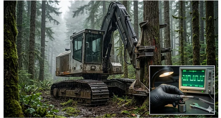
I told the field tech to grab a four-channel oscilloscope, put a high-speed current clamp on the PTO solenoid feed, and run differential probes across CAN Hi and CAN Lo at the transmission ECU. Thirty seconds after the PTO engaged, the root cause painted itself across the screen.
The solenoid was a PWM-controlled proportional valve. On every PWM off-cycle, the flyback voltage spike punched past two hundred volts. Worse, the solenoid body was bolted to a steel bracket that shared a ground path with the CAN shield drain. That bracket wasn’t just a mechanical anchor — it had become a radiating antenna. Each PWM pulse injected a common-mode spike straight onto the J1939 backbone.
What had been a clean two-and-a-half-volt recessive level shifted to a three-volt common-mode offset — far outside the common-mode range of any commercial CAN transceiver. Error frames piled up, the ECU declared a bus-off state, and the transmission dropped to neutral. Recovery demanded a full key cycle: kill the engine, lose hydraulic pressure, and burn minutes you can’t get back. If you’ve never set up this measurement yourself, our guide to J1939 common-mode voltage shift measurement walks through the exact probing technique.
The textbook answer was “add more shielding,” except this harness already carried shielded twisted pair. The real problem? The shield drain was tied to chassis ground at both ends — a textbook ground loop. With high-frequency noise riding on that bracket, the shield had turned into a low-impedance path directly into the ECU ground plane. The solution wasn’t more shielding. It was correcting how the shield referenced ground and killing the noise at its source — the solenoid itself.
The fifty-dollar fix
I drew a napkin sketch. Each PTO solenoid would get a transient voltage suppressor (TVS) placed directly across the coil, tucked inside the connector backshell. The shield would be terminated at the ECU end only — single-point shield termination. And the solenoid ground return would run its own dedicated wire straight to the engine block, never touching the chassis bracket.
The bill of materials was almost embarrassing: a compact bidirectional TVS diode rated for the load, a few inches of tinned copper braid, adhesive-lined heat shrink, and a machined aluminum shield cover that slipped over the solenoid connector and bonded to that dedicated ground lead. Component cost per unit landed at roughly forty-eight dollars. With labor to build and test, a finished shield assembly came out to fifty dollars per machine.
What we call a “shield” is actually a tuned suppression kit. The braid forms a Faraday cage around the connector, the TVS clamps the flyback transient at its origin, and the single-point grounding keeps common-mode current off the bus. No black magic — just applied EMC fundamentals that heavy equipment too often ignores.
Field results that changed how the fleet operates
We retrofitted two machines on day one and ran them through normal duty cycles — felling, bunching, processing. Zero CAN bus errors. Zero dropouts. The scope trace showed common-mode noise flatlined below half a volt, even with the saw buried in wood and the PTO cycling aggressively. By noon the next day, the fleet manager had authorized the remaining twelve machines. Total downtime prevented, from his own spreadsheet, exceeded twelve thousand dollars inside the first month.
Here is what the error log looked like before and after:
| Condition | Before Shield | After Shield |
| CAN bus error frames per hour | 340–1,200 | 0 |
| Involuntary transmission neutral events per shift | 5–9 | 0 |
| Peak common-mode voltage at ECU (V) | 3.1 | 0.4 |
| Key cycles per machine per day | 4–7 | 0 |
Common mistakes that make PTO interference worse
Over the years I have walked onto a lot of job sites and watched the same patterns repeat. What follows are the specific mistakes that turn a manageable electrical noise issue into a full-blown fleet-wide shutdown — each one pulled directly from measurements I took on the Cascade job or on machines just like them. If you’re fighting a PTO-induced bus crash right now, the diagnostic framework I laid out in the PTO J1939 interference diagnosis and shielding guide may save you the first four hours of scope work.
- Grounding the shield at both ends. On those harvesters, we measured 0.3 V of ground potential difference at idle between the cab bracket and the engine block. Under full alternator load, that gap widened to over 2 V. With the shield drain bonded on both sides, that voltage differential drove current straight through the braid and into the ECU reference plane — transforming the shield from a protective barrier into an injection mechanism. A three-tenths-of-a-volt offset sounds small, but as we’ve documented separately, a 0.3 V ground offset on a J1939 backbone can double your error frame rate under load.
- Return path sharing. One forwarder had the PTO solenoid return and the transmission pressure sensor return spliced together inside the same Deutsch connector cavity. Every PWM off-cycle yanked the sensor ground up by 1.8 V. The ECU then calculated a transmission line pressure that did not exist, triggering an implausible-gear fault while the gears themselves were mechanically intact. Fleets routinely underestimate how connector choice affects noise margins; our J1939 Deutsch DT and HD connector guide explains why cavity assignment matters every bit as much as the connector shell.
- Using unshielded solenoid connectors. On one harvester, the solenoid connector was a standard Deutsch DT with no backshell. A near-field probe six inches away measured broadband noise from 50 MHz all the way to 400 MHz — strong enough to swamp the CAN transceiver’s input stage. Replacing it with a shielded connector body cut that radiated field by over 20 dB.
- Ignoring flyback suppression. I pulled the connector on a PTO valve that had run without a flyback diode for three seasons. The coil insulation had carbonized from repeated 200 V spikes, and the relay contacts in the upstream control module were pitted to the verge of intermittent contact. A diode costing less than a dollar would have prevented both failures.
- Assuming twisted pair is enough. On a forwarder where the twisted pair ran within four inches of the PTO solenoid harness for eight feet, the differential signal looked textbook-perfect on a scope — until we measured common-mode. The entire bus was riding on a 1.5 V, 15 kHz ripple that mirrored the PWM duty cycle. Without a properly terminated shield, the twisting contributed exactly nothing.
How to confirm the fix is real
I don’t trust any fix until I see it on a scope and log it over time. The baseline validation sequence I use every time:
- Differential CAN measurement at the terminating ECU: Look for a clean recessive level of 2.5 V and a dominant differential around 1 V. Any common-mode offset that forces the recessive level outside the 0.5–4.5 V window is a hard red flag. If you’re new to this measurement, our J1939 waveform analysis guide using a USB scope shows the exact setup and the kind of screen captures you should expect.
- Current waveform at the PTO solenoid: Verify the flyback pulse amplitude. With proper transient suppression, the spike must remain clamped below forty volts above system voltage on heavy inductive loads.
- Current waveform at the PTO solenoid: Verify the flyback pulse amplitude. With proper transient suppression, the spike must remain clamped below forty volts above system voltage on heavy inductive loads.
- Six-hour duty cycle log with zero fault counts: If a single J1939 error frame increments during that window, you still have an undiscovered coupling path.
Building these in a factory that treats harnesses like a tier-one component
I’ve dealt with harness suppliers who ship product without performing a basic continuity check. That’s unacceptable when one intermittent connection can park a quarter-million-dollar machine on a slope — a reality we’ve quantified at over eighteen thousand dollars per machine annually when intermittent J1939 faults go undiagnosed.
Because we maintain IATF 16949 traceability from raw material receipt through final shipping, every inch of tinned copper braid and every TVS diode in those kits is traceable to its incoming lot. The four-step inspection sequence — automated continuity and hipot, shield integrity test, crimp pull force measurement, and magnified visual audit — wasn’t written for a brochure. It exists because we’ve watched a single cold-crimp joint strand a machine on a slope, and we refuse to let that happen on a harness that carries our laser-marked name on the jacket.
We run a 5S-managed production line inside a climate-controlled warehouse because humidity and temperature swings alter insulation resistance and can bury latent failures that only surface in the field. All raw materials — connector housings, braid, everything — meet RoHS and REACH compliance. Every assembly is 100% tested, never batch sampled. That’s the same discipline that lets us take a Wednesday phone call for twelve custom shield kits and ship them by Friday without layers of approvals. Those small details separate a harness that survives a season from one that survives a decade.
This direct OEM customization capability extends to every dimension of a custom cable assembly: you specify the connector brand, wire AWG, overall length, jacket color, and we laser-mark your logo and part number. No minimum order quantity calibrated only for automotive build rates. This is engineered-to-order harness work delivered at factory-direct speed.
FAQ: answers that come up on every PTO noise investigation
1. Is PTO interference only a forestry equipment problem?
I’ve found the same failure signature on refuse trucks, concrete pumps, and agricultural sprayers. Any mobile hydraulic application that pulses a high-current inductive load near a CAN bus will eventually run into this.
2. Can I fix this with a software filter?
We tried. Before the shield kit went on, the dealer increased the J1939 retry counter and widened the sample point window. It bought an extra fifteen minutes before the bus-off event — until the next heavy PTO engagement, when the common-mode offset again crossed 3 V. A transceiver cannot decode differential bits when its input pins are forced outside the common-mode rating. That is a physical-layer violation, and no software workaround survives it. Tweaking the sample point is a band-aid; our J1939 sampling point diagnostics article explains when it masks a problem and when it makes things worse.
3. We already have shielded cable. Why do we need a shield kit?
The Cascade harvesters arrived with factory-supplied shielded cable, yet the bus crashed every duty cycle. The issue wasn’t the absence of shielding — it was that the shield drain was bonded to the same bracket carrying PTO return current. Once we floated the solenoid end and re-referenced the drain to the engine block, the noise path vanished. The kit doesn’t add shielding; it corrects the termination. That said, termination is only half the equation — if the cable shield and jacket have already degraded from moisture ingress or UV exposure, even a correctly terminated harness will eventually fail. We’ve pulled apart logging cables where the shield braid had turned to green powder inside an intact outer jacket.
4. Is a metal connector body better than plastic for noise?
Not by default. A metal body can deliver better high-frequency shielding if it’s properly bonded to the shield. On the Cascade machines, we used a full-plastic RoHS-compliant connector body and matched the shielding effectiveness of a metal prototype simply by extending the tinned braid into the connector backshell. The geometry matters more than the material.
5. Does a TVS diode slow down the solenoid response?
We bench-tested this with a pressure transducer on the solenoid output. A TVS with a parasitic capacitance of 20 pF introduced no measurable delay in the valve spool’s rise time. What did change: the flyback spike dropped from 210 V to 36 V. The solenoid’s mechanical response curve was identical within the resolution of our pressure gauge.
6. What pinout changes are needed to retrofit?
In most cases, you add one dedicated drain wire from the solenoid connector to engine ground and float the shield at the solenoid end. The CAN lines stay untouched. A typical 4-pin solenoid connector gets repinned to add the ground circuit without touching the ECU connector.
7. How long does a shield kit last in logging conditions?
The kit uses tinned copper braid with an adhesive-lined heat shrink jacket. After twelve months on these harvesters — daily rain, hydraulic oil spray, and constant vibration — we have zero reported failures. Insulation resistance still measures above five hundred megaohms.
8. Can I test the shield effectiveness without a scope?
You start with a multimeter to confirm the shield ground path is single-point and isolated at the far end, and you should. On one machine, we found 4.7 ohms between the shield drain and engine ground just by probing at the connector — enough to flag a frayed drain wire. But to see common-mode noise, you need a scope. A handheld oscilloscope with differential probes, even a 20 MHz model, will reveal a 3 V offset. Every fleet should carry one in the service truck.
9. Why not just replace the entire machine harness?
A full harness replacement on one of these forwarders would run close to four thousand dollars in parts alone, plus two days of labor. And if the new harness still lands the solenoid ground on a noisy chassis point, the interference returns. The fifty-dollar shield kit targeted the exact coupling mechanism. Field install time: twenty-two minutes per machine, and the problem stayed gone.
10. Where do I start if I have multiple machines with the same symptom?
Call an applications engineer who can walk you through the measurement setup. Don’t shotgun parts. A ten-minute scope capture points you in a better direction than a week of guesswork. And if you need the shield kit built to your connector and length spec, you go to a factory that can turn engineering samples quickly.
If your own J1939 log shows a spike of error frames the moment a PTO engages — or if you’ve already swapped ECUs and harnesses without closing the case — don’t start over. Send your scope traces or a description of the fault pattern. Our engineering team works from your pinout, your connector type, and your mechanical constraints. We’ll help you determine whether a fifty-dollar tuned suppression kit kills the problem, or if there’s a different noise path you haven’t uncovered yet.
Reach the team directly on WhatsApp to discuss your application and get engineering support:
Or use our contact page to submit your specs and request an engineering review:
We build to your spec, with your logo, your color, and your AWG. Engineering support comes direct from the factory floor — no catalog guesswork.
