

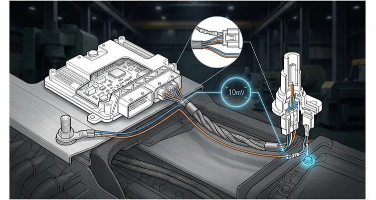
You have seen the line item in a customer drawing. You have likely heard it argued about in a design review. Someone points to the schematic and says, “The reference ground offset between the sensor and the ECU must not exceed ten millivolts.” Then the room goes quiet because nobody wants to admit that ten millivolts is almost impossible to measure reliably on a running engine, yet the program will be halted if you ignore it.
I have spent most of my career inside the wiring that connects sensors to control units. I have cut apart failed harnesses, sat in front of oscilloscopes at three in the morning, and argued with design engineers about what a ground really is. This note is not a textbook definition. It is a practical explanation of where the 10mV rule comes from, what it actually protects, and how to build a harness that respects it without designing yourself into a corner.
The Real Reason Ten Millivolts Became the Magic Number
The 10mV limit is not a precision target. It is a boundary where the ECU’s input stage can no longer separate the sensor’s real output from the noise floor created by its own ground return. A modern ECU input channel for a thermistor, a pressure transducer, or a differential sensor is sampling at high speed. The processor is doing what it does best: comparing one voltage to another. If the ground reference at the sensor is shifted by a few millivolts relative to the ground reference inside the ECU, the processor does not see the real signal. It sees the signal plus the error.
If that offset creeps up, the ECU starts making decisions on corrupted data. For a 0-5V analog sensor—and you can see the difference in single-ended vs. differential ADC inputs for MAP sensors—a ten-millivolt offset is a 0.2% full-scale error. That does not sound like much until you realize that the ECU is using that error to calculate ignition timing, fuel trim, or emissions strategy. A 0.2% error in a temperature reading can shift an emissions control routine enough to fail a cold-start test in a climatic chamber.
Why not five? Because in production, ten millivolts is the line between what you can control and what you cannot. Below it, you are chasing thermal noise, connector oxidation, and crimp tolerance stacks. Above it, you get repeatable field failures. The engineers who wrote that spec didn’t pull the number from a textbook. They drew the line after looking at warranty returns from failed sensor circuits.
The Physics Behind the Offset
A 0.5 mm² ground return in a three-meter harness run is not a zero-ohm path. At 80°C, its resistance is already over thirty milliohms. Push two amps through it and you have a sixty-millivolt drop before you even consider the connector terminals. The problem is that your “ground” wire is carrying current from multiple loads. Every time an injector fires, a fan kicks on, or a solenoid de-energizes, the current through the ground return changes. That changing current creates a changing voltage drop.
If the harness is asymmetric—say one conductor is slightly longer or routed differently—you can get cable asymmetry driving common-mode noise with a 12 percent mismatch. That noise shows up directly as offset. And if your sensor shares that ground path with a high-current device, the sensor’s local ground voltage bounces around. The ECU, sitting at the other end of the harness, sees a relatively stable ground. The difference between the sensor’s bouncing ground and the ECU’s stable ground is your offset. If that peak-to-peak bounce exceeds ten millivolts, you have a problem.
Thermoelectric EMF: The Hidden Offset Source
There’s a second offset source most harness drawings never mention: thermoelectric EMF. When you join two dissimilar metals at a connector or a splice, you create a tiny thermocouple. If one side of that junction is hot and the other is cold, you generate a voltage. In a high-temperature engine bay, a poorly chosen connector plating can generate several millivolts on its own. I have seen a “perfect” harness fail a 10mV spec on a dynamometer simply because the connector at the sensor was heated by the exhaust manifold while the ECU end stayed cool. The offset was not from resistance; it was from the Seebeck effect.
What Happens When You Violate It (A Case From the Field)
A few years ago, we were called in to review a harness for a small off-highway diesel application. The customer had a production run of engine controllers that were intermittently dropping sensor signals. The reported symptom was a “glitch” in the intake manifold pressure reading during wide-open throttle events.
We traced the harness. The sensor ground and the ground for the fuel injectors shared a common splice. The splice was located near the injector rail, where temperatures were high and vibration was severe. Under full load, the injector current was high enough to create a voltage drop across that shared splice and the wire run to the ECU.
The measured offset was fourteen millivolts peak. The ECU’s input filter was not rejecting it. The result was a momentary fuel correction that caused the engine to stumble. The fix was not a software change. It was a harness re-route: separating the sensor ground and the injector ground into dedicated returns, with a single common point at the ECU. The offset dropped to under four millivolts. The symptom disappeared.
That job cost the OEM in the low six figures when you counted the field service time, the rework, and the line stoppage. All because a splice was located six inches from where it should have been. For a larger-scale failure on a digital bus, see how a 0.3V ground offset on a J1939 backbone cost nine thousand eight hundred dollars. The physics is the same; the price tag just gets bigger.
The Difference Between Chassis Ground and Signal Ground
Inside a vehicle harness, the word “ground” appears on three different schematic pages. Two of them will kill your sensor signal if you connect them at the wrong end. In a vehicle, you have the chassis ground, which is a big, noisy conductor. You also have signal grounds inside the harness. A sensor ground should never be tied directly to the chassis at the sensor end. If you do, you are using the chassis as a return path, and the chassis is carrying hundreds of amps of noise from the alternator, the motors, and the ignition system.
Chassis Ground vs. Signal Ground at a Glance
| Characteristic | Chassis Ground | Signal Ground |
| Primary purpose | Return path for high-current loads | Return path for low-level analog signals |
| Typical current | Tens to hundreds of amps | Milliamps to a few amps |
| Voltage stability | Very noisy, large transients | Must be quiet, minimal offset |
| Connection to sensor | Never directly | Dedicated twisted pair to ECU |
| Impact on 10mV spec | Destroys it if shared | Preserves it if isolated |
The correct method is to run a dedicated, twisted-pair ground wire from the sensor back to the ECU’s analog ground pin. That wire should not be shared with any other load. It should not be spliced into a power ground. It should be isolated from the chassis except at the single point where the ECU itself is grounded to the chassis.
When I am writing a test plan for a new harness, I always ask for three things: a schematic that shows the ground topology, a physical layout that shows where the splices are located, and a sample harness that I can measure before it goes into production. If the schematic does not clearly separate signal ground from power ground, I know there will be problems.
Step-by-Step: How to Measure Ground Offset Correctly
You cannot measure a ten-millivolt offset with a standard handheld multimeter and expect to see the whole picture. You need a differential measurement, and you need to do it under load.
- Power the system under worst-case load. Turn on every high-current device at once. Run the engine at full RPM, turn on the fans, the lights, the wipers, and the injectors. The offset is not a static value; it is dynamic.
- Connect your oscilloscope across the sensor ground and the ECU ground. Use a differential probe or two channels with the math function set to subtract. Do not use a single-ended probe with the ground clip tied to the chassis. That will introduce its own loop and corrupt the measurement. Set the scope to 5 mV/div and 2 ms/div. If you use a passive probe, switch it to 10x and set the bandwidth limit to 20 MHz—you are not trying to measure switching noise, you are trying to see the low-frequency bounce from injector current. (If you are wondering about scope bandwidth, this same principle is explained in why a 50 MHz scope misses a glitch that a 100 MHz scope catches.)
- Verify the vertical scale. You are looking for the peak-to-peak deviation, not the average. The spec is usually written as a maximum absolute value, but the real enemy is the dynamic swing.
- Capture for at least ten seconds. You are looking for transient events: injector pulses, solenoid de-energizing, PWM fan changes. These are the moments when the offset spikes.
- Record the maximum positive and negative peaks. If the sum of those peaks exceeds ten millivolts, you have a violation, even if the average is close to zero.
- Repeat the test on a hot engine. Resistance increases with temperature. A harness that passes at room temperature may fail at 120°C because the copper resistance has increased by roughly 39%.
- Check the connectors. Disconnect and reconnect each connector three times and repeat the measurement. Oxidation and contact wear can add millivolts over time. A harness that passes when new may fail after fifty thermal cycles.
If the offset you are chasing is on a digital bus rather than an analog sensor input, the measurement setup changes. We covered that workflow in our J1939 ground offset diagnosis guide.
Five Mistakes That Silently Ruin the Measurement
Mistake 1: Measuring without load. An unloaded ground path carries almost no current, so the voltage drop is near zero. You will see a beautiful, flat line on the scope and think you are fine. Then the engine starts and the offset appears. Always measure under worst-case electrical load.
Mistake 2: Using the wrong ground reference. If you clip your oscilloscope ground to the battery negative terminal, you are measuring the voltage at the sensor ground relative to the battery, not the ECU. The battery is not the ECU’s analog ground. You must measure across the exact two points the ECU is comparing.
Mistake 3: Ignoring the wire gauge. A 22 AWG ground wire is cheap and light. It also has a resistance of about fifty-three milliohms per foot. Push one amp through a ten-foot run, and you have already lost over half a millivolt before you account for the return path. For a sensor that draws only a few milliamps, that is fine. For a sensor that shares a ground with anything else, it is not. If you are setting up a test bench, pay close attention to AWG, loop resistance, and ground separation on the bench.
Mistake 4: Letting the harness float at the sensor end. Some people wrap the sensor ground in shielding but then leave the shield floating at the ECU end. The shield then acts as an antenna, picking up radiated noise and coupling it into the signal. The shield must be tied to ground at exactly one point—the ECU. If you tie it at both ends, you create a ground loop that adds noise instead of removing it.
Mistake 5: Assuming the spec is a design target. Ten millivolts is a limit, not a goal. If your nominal design is sitting at eight millivolts, you have no margin for aging, temperature, connector wear, or manufacturing variation. A good design targets three millivolts or less, so that you can tolerate the real-world drift that happens over the life of the vehicle.
How We Build Harnesses That Respect the Rule
At our factory, we have been cutting, crimping, and assembling sensor harnesses for over twenty-one years. The 10mV rule is not an abstract requirement for us; it is a daily engineering constraint. When a customer sends us a drawing that shows a shared ground splice, our engineers flag it before we cut the first wire.
We control the variables that matter. We use full-copper conductors with no recycled content. We specify tin-plated copper strands to minimize thermoelectric EMF at the connectors. We do not mix plating types in the same circuit unless the customer explicitly approves it, because mixing tin and gold in the same junction creates a thermocouple that can generate microvolt-level noise.
Every harness goes through a four-step quality inspection. First, a continuity check on every conductor. Second, a high-voltage hipot test to catch insulation faults. Third, a crimp pull-test on a sampling basis to verify mechanical integrity. (Crimp quality matters because even small crimp resistance drift can produce a 100mV ground offset.) Fourth, a visual and dimensional audit against the customer print. For circuits that carry sensitive analog signals, we can add a millivolt-drop test under a defined load so that the customer knows exactly what the harness will do in the field before it ships.
Our facility operates under ISO 9001 and IATF 16949 disciplines. We also maintain ISO 14001 environmental management certification. We are familiar with PPAP documentation, including process flow diagrams, control plans, and dimensional reports. If your program requires salt spray testing for connector plating or environmental validation, we can arrange that through our in-house lab and give you the data in a format your quality team can use immediately.
When the 10mV Rule Becomes a Negotiation
Sometimes the spec is not achievable without changing the harness architecture. A customer may have designed a sensor with a return path that goes through a twenty-foot-long bundle of other signals. The crosstalk from a PWM motor control line can induce millivolts of noise onto the sensor ground through capacitive coupling alone.
When that happens, the correct answer is not to ignore the spec and hope for the best. The correct answer is to go back to the customer with data. Show them the measurement. Show them where the offset is coming from. Then propose the fix: a dedicated twisted-pair return, a shielding change, a relocated splice, or a change in wire gauge.
Not once have I watched a customer reject a technical argument when the scope captures and the physical explanation were laid out side by side. They may push back on cost, but that is a different conversation. The engineering conversation is about making the system work. The commercial conversation is about who pays for the extra wire. Keep them separate.
How to Confirm You Have Fixed the Problem
The proof is not a simulation. It is a measurement on a production-intent harness, installed in a vehicle, under real operating conditions. Run the test I described above. If your worst-case peak-to-peak offset is under ten millivolts with margin to spare, you have a robust design. Document the test setup, the load conditions, and the results. Put that report in the PPAP package. It will save you arguments later.
If you are not sure whether your current harness is violating the rule, send us a sample. We can build a test fixture, apply the load profile, and capture the offset. We have done this for OEMs, Tier 1 suppliers, and aftermarket companies. The data usually tells the same story: the harness is the variable that everyone assumed was fine. Before you go down the path of replacing an expensive ECU, read our guide on how to avoid ECU replacement by diagnosing ground offset first.
Related Products and Capabilitie
We manufacture a range of sensor cables, ECU adapter harnesses, and custom ground returns for automotive and off-highway applications. If your program involves differential sensors, temperature probes, or pressure transducers, we can provide a harness that is designed to minimize ground offset from the start.
Our OEM customization includes wire gauge selection, shielding, connector choice, color, length, and labeling. We can work from your drawing or help you develop a harness from a rough sketch. We supply both prototype quantities and production volumes. No order is too small to start a conversation, and no technical question is too basic.
FAQ: The 10mV Rule in Practice
1. Our customer’s drawing says 5 mV. Our competitor says 10 mV is fine. Who is right?
Your customer is right because their drawing is the binding specification. Some OEMs specify five millivolts for critical emissions sensors. Others allow twenty millivolts for less sensitive applications. The ten-millivolt figure is a common benchmark, but if a drawing says five, you design for five or you get a formal deviation in writing. Do not assume a competitor’s rule of thumb overrides the print.
2. We grounded our sensor to the engine block and the offset is huge. What went wrong?
The engine block is a chassis ground, not a signal ground. It carries massive current transients from the starter, alternator, and ignition system. A sensor ground should be a dedicated wire back to the ECU’s analog ground pin, twisted with the signal wire, and isolated from the chassis except at the ECU’s single ground point.
3. We have two pressure sensors sharing one ground return. The ECU sees noise on both. Is that the problem?
Almost certainly. One sensor’s current draw creates a voltage drop that the other sensor sees as an offset. This is called ground coupling. Use a separate return for each sensor, or at least a dedicated return per signal group. The cost of one extra wire is far less than the cost of a failed validation test.
4. We only use CAN sensors. Do we still need to worry about the ten-millivolt limit?
No, not in the same way. Digital signals like CAN and LIN have noise margins measured in hundreds of millivolts. The 10mV rule applies to analog inputs where the ECU is converting a continuous voltage to a digital value. Digital grounds still need care, but the tolerance is much larger. Check your customer’s spec for digital ground offsets separately.
5. Why does our harness pass at room temperature but fail on the dyno after twenty minutes?
Copper resistance increases about 0.393% per degree Celsius. A wire that measures one milliohm at room temperature will measure about 1.39 milliohms at 120°C. The offset scales with resistance, so a hot engine will show a higher offset than a cold bench test. Run your measurement hot, not just after a quick warm-up.
6. We changed the connector supplier and the offset went from 6 mV to 12 mV. What happened?
Connector contact resistance can be several milliohms, and it varies widely by terminal design, plating, and retention force. A single worn or low-quality connector in the ground path can add millivolts. That is why we specify high-retention terminals and perform repeated mating cycles in our validation. The cheaper connector may have lower initial resistance but degrade faster under vibration and thermal cycling.
7. Is the ten-millivolt spec the same as a voltage drop test?
Not exactly. A voltage drop test measures the DC drop across a single wire or connection under a steady current. The 10mV rule is about the dynamic difference between two reference points under operating conditions, including transients from injectors and solenoids. You can use a voltage drop test as a rough screening tool, but it will not catch transient offsets.
8. What wire gauge should we use for a sensor ground that runs four meters to the ECU?
There is no universal answer. For a passive thermistor drawing a few milliamps, 22 AWG is often fine. For a sensor with a heated element or a long run, you may need 18 AWG or larger. Calculate the expected current and the round-trip resistance, then target an offset below three millivolts. A four-meter run at 22 AWG with one amp of shared current will already eat up your entire margin.
9. We twisted the sensor pair but left the shield floating at the ECU. Is that okay?
No. A floating shield acts as an antenna, picking up radiated noise and coupling it into the signal. The shield must be tied to ground at exactly one point—the ECU. If the shield is also used as the signal return, that is a different design, but it must be called out on the customer print. Do not leave any shield floating.
10. We don’t have a vehicle available. Can we do the ten-millivolt test on a bench with a power supply?
Yes, but you must replicate the load conditions. Use a power supply that can deliver the same current profile as the real system. Connect a resistive load to simulate the injectors or motors. Measure the offset across the exact points the ECU will use. A bench test is valid if the loads are realistic. If you skip the dynamic loads, you will get a number that means nothing.
Need help with a harness that has to meet a 10mV ground offset spec?
We deal with this every day. Send us your drawing, your test data, or just your problem description. Our engineers will review it and give you a straight answer. No pressure. Just a conversation with people who know how to build the wiring right.
Contact us through our inquiry page or reach out directly on WhatsApp to talk about your application.
