

J1939 Communication Fault Codes That Point to the Wrong Problem
The truck had rolled into the shop with a straightforward complaint: intermittent instrument cluster blackout, followed by a no-crank condition. The shop techs pulled the standard DTCs using a J1939 diagnostic tool — and that’s where things got misleading.
The fault codes were all over the map:
| Fault Code | Description | Occurrence |
| SA 0, SPN 639 | J1939 Network #1, Abnormal Update Rate | 47 counts |
| SA 0, SPN 1231 | J1939 Network #2, Abnormal Update Rate | 31 counts |
| SA 3, SPN 168 | Battery Potential / Power Input | 3 counts |
| SA 49, SPN 3050 | Aftertreatment SCR Catalyst Efficiency | 1 count |
The shop focused on the most frequent codes — the network communication faults — and assumed an ECU internal failure. The logic was understandable: if the engine ECU stops communicating, everything downstream goes dark. But the logic was wrong.
A single, isolated ECU failure on a J1939 network does not cause a dashboard blackout. The J1939 backbone is a differential bus. If one node fails short or open, the rest of the network continues communicating. A complete bus collapse means something is pulling the physical layer out of spec across the entire backbone. I’ve seen this misdiagnosis play out in fleet shops more times than I can count — a tech sees communication DTCs, condemns the most expensive module on the bus, and the truck comes back two days later with the same fault.
That’s not an ECU problem. That’s a bus topology problem. Specifically, it’s a CAN bus termination resistance problem hiding in plain sight, where the only tool needed to find it costs less than the fuel to drive the truck into the bay.
The Physical Layer: What Gets Skipped
J1939, like every CAN-based protocol in heavy-duty vehicle networks, relies on a twisted-pair differential bus. The two signal lines — CAN High and CAN Low — must maintain specific voltage levels and impedance characteristics for the transceivers to interpret dominant and recessive bits correctly. When these electrical parameters drift, the entire communication stack collapses from the bottom up. This is the J1939 physical layer at work, and it does not negotiate. The CAN bus standard, originally developed by Bosch and now governed under ISO 11898, defines these electrical specifications precisely — and J1939 inherits every one of them.
The specification requires exactly two terminating resistors, each 120Ω, placed at the extreme ends of the backbone. These resistors sit between CAN High and CAN Low. When the bus is unpowered and all ECUs are in their recessive state, measuring resistance across CAN High and CAN Low at any point on the backbone should read approximately 60Ω — the parallel equivalent of two 120Ω resistors. This is the 60 ohm termination resistance test that every technician should perform before connecting a scan tool.
I’ve watched technicians spend hours deciphering J1939 fault codes that read like tea leaves. Here’s the rule that was drilled into me twenty years ago on a factory floor and hasn’t failed yet: the network doesn’t care about your scan tool until it has a clean electrical foundation. If you haven’t put a meter on CAN High and CAN Low, you haven’t started diagnosing. You’re just guessing with software. A basic J1939 physical layer troubleshooting sequence starts with resistance, moves to voltage, and only then looks at data.
Mark’s shop skipped it. For four days.
The Measurement That Told the Truth
When I arrived on-site, the truck was in the third bay, hood up, battery cables disconnected. The previous shift had left a stack of swapped parts on a rolling cart — a replacement engine ECU, a used instrument cluster, and a new ignition switch still in the packaging. Total parts cost already exceeded two thousand dollars, none of which solved the problem.
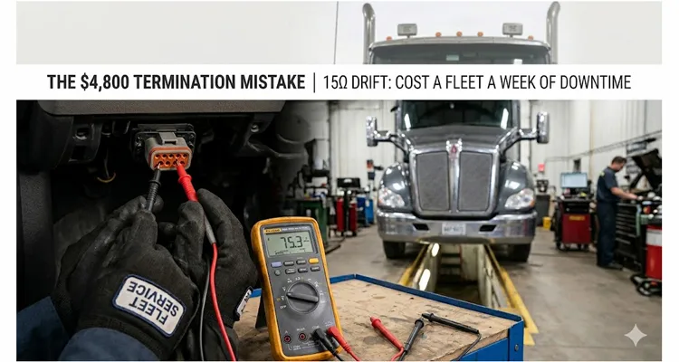
I grabbed a Fluke 87V and set it to ohms. The truck’s batteries had been disconnected for over an hour, so residual capacitance in the ECU power supplies had fully discharged. This is critical — measuring termination resistance with powered modules in the circuit can give misleading readings due to internal biasing circuits pulling the value away from the true passive resistance of the terminating resistors.
Accessing the J1939 backbone was straightforward on this T680. The diagnostic connector under the dash provides direct access to CAN High (Pin C) and CAN Low (Pin D) for the primary network. I back-probed the connector.
The expected reading: 60Ω.
The actual reading: 75.3Ω.
Seventy-five ohms. That’s a fifteen-ohm deviation from spec. In the world of CAN bus termination, that’s not a minor drift — that’s a bus on the verge of collapse. When I see a reading like this, I already know I’m looking at a J1939 termination resistance drift that has been developing for months, not days.
Let me explain why.
How a 15 Ohm Increase in CAN Bus Termination Resistance Causes Network Collapse
A CAN transceiver drives the bus differentially. In the dominant state, CAN High is driven to roughly 3.5V and CAN Low to roughly 1.5V, creating a 2V differential. In the recessive state, both lines float to approximately 2.5V, creating a 0V differential.
The terminating resistors serve two functions. First, they eliminate signal reflections by matching the characteristic impedance of the twisted-pair cable. Without proper termination, those reflections bounce back and forth along the backbone, corrupting bits. This is how a J1939 bit sampling error begins — not from a software bug, but from a physical impedance mismatch. Second, they provide a discharge path that returns the bus to the recessive state when no transceiver is actively driving it. This is the function most techs overlook. The underlying physics is governed by transmission line theory, which dictates that any impedance discontinuity along a conductor pair will reflect a portion of the signal energy back toward the source — exactly what was happening inside Mark’s backbone.
When the termination resistance drifts upward — from 60Ω to 75Ω in this case — the RC time constant of the bus changes. The recessive state discharge takes longer. At 250 kbps, the J1939 standard data rate, the bit time is 4 microseconds. If the bus doesn’t fully return to recessive within that window, the next bit gets corrupted. You get bit errors that no scan tool will flag with a neat “check termination” message. The ECU simply sees a corrupted frame and increments an error counter. Enough of those, and the CAN controller triggers a bus-off state.
What the shop saw as “intermittent communication” was actually a bus that worked just well enough to pass frames in cool ambient conditions, then failed catastrophically when temperature, vibration, or electrical noise pushed it over the edge. On the production floor, we call these “seasonal faults” — they appear in October and disappear in April, because the physics of resistance drift is temperature-dependent. I’ve written about this thermal behavior in detail before: J1939 termination resistance drift behaves differently hot versus cold, and understanding that relationship is what separates a parts-swapper from a diagnostician.
The fifteen-ohm drift translated to approximately 25% longer discharge time. At 250 kbps, that’s enough to cause a 15-20% bit error rate on longer J1939 frames. The engine ECU, sitting in the middle of the backbone, was seeing mangled frames and responding with error frames. Enough error frames in sequence trigger the CAN controller’s bus-off state — the ECU disconnects itself from the bus to avoid flooding it with errors. This is a self-preservation mechanism built into every CAN controller on the network. The result is a J1939 bus-off event triggered by bit sampling errors and signal reflections — exactly what happened inside Mark’s T680 while the shop was swapping ECUs.
When the engine ECU went bus-off, the dashboard lost its primary data source. The cluster, not receiving expected periodic frames, triggered its own timeout routines and blanked the display.
All of this cascaded from a passive component failure that costs less than three dollars. A three-dollar terminating resistor crippled a hundred-thousand-dollar truck.
The Hunt: Finding the Drifted Resistor
Knowing you have a termination problem is step one. Finding which resistor has drifted is step two — and this is where the diagnostic logic separates a parts-swapper from someone who actually understands network topology.
The J1939 backbone on this T680 runs approximately 14 feet, from the engine bay connector near the firewall, through the dash harness, to a junction block behind the glove box. There are exactly two termination points per the OEM wiring diagram: one integrated into the engine ECU connector housing, and one inside the cab at the far end of the backbone, embedded in the instrument cluster harness connector. This is standard J1939 backbone design — two terminators at the extreme ends, and every ECU connected via short stub lengths.
The measurement procedure is systematic:
- Isolate the network. Disconnect both termination points from the bus. This removes the parallel paths and lets you measure each terminator independently.
- Measure each resistor individually. The spec is 120Ω ± 1%. Anything outside that window is a problem waiting to strand a truck.
- Measure the wiring harness itself. With both terminators removed, resistance across CAN High and CAN Low should read open circuit. Any finite resistance indicates wiring damage or contamination between the conductors.
I started at the engine side. The terminator there is a small two-pin connector plugged into the engine ECU harness, about four inches from the main ECU connector. Unplugged it. Measured: 120.2Ω. Perfect.
Moved to the cab. The instrument cluster side required pulling the cluster out of the dash — four screws and two harness connectors. The terminating resistor on this model is not a separate plug; it’s molded into the cluster harness connector body, a small sealed module with two pins bridging CAN High and CAN Low.
Measured across those two pins: 152.8Ω.
There it was. The cab-side terminator had drifted from 120Ω to nearly 153Ω. That’s a 27% increase, well outside even a generous tolerance window. In parallel with the good 120Ω engine-side terminator, this gave the 75Ω reading at the diagnostic connector. The math checks out: 120Ω in parallel with 153Ω gives you roughly 67Ω at room temperature, but with the engine heat-soaking the firewall side and the cab side cold, that parallel value drifted higher. Anyone who has performed a 60-ohm waveform analysis on a J1939 backbone would recognize this signature immediately — the waveform doesn’t lie when the resistance does.
The Root Cause: Moisture, Time, and Material Degradation
The failed resistor module was cut open on the bench. Inside was a simple thick-film chip resistor encased in potting compound. Under magnification, the solder joint between the resistor body and one of the terminal pins showed a fine network of cracks radiating outward from the pin. There was also visible corrosion at the pin-to-pad interface — the telltale signature of moisture ingress over multiple thermal cycles.
This truck operated in the upper Midwest. It saw road salt, freeze-thaw cycles, and enough humidity to push moisture into any connector that wasn’t hermetically sealed. The potting compound around the resistor had a hairline fissure — likely a manufacturing defect introduced during the curing process — that allowed atmospheric moisture to reach the termination point. Once moisture bridges the gap between two conductors at different potentials, galvanic corrosion begins. It’s slow, it’s relentless, and no scan tool will ever report it.
Over approximately eighteen months of service, the combination of galvanic corrosion and thermal expansion cycling degraded the solder joint. The resistance crept upward gradually. The bus compensated — until it couldn’t.
The crack in that potting compound was invisible to the naked eye. Under 20x magnification, it was unmistakable — a hairline path from the connector body seam straight to the resistor pad. This isn’t a failure you catch with a continuity tester on a production line. It’s a failure you prevent by controlling how the potting compound is mixed, degassed, and cured — steps that happen on a factory floor, not in a service bay. When our production team runs a batch of sealed connector assemblies, the potting process includes vacuum degassing specifically to eliminate the micro-bubbles that eventually become moisture paths like the one that killed Mark’s terminator. This is the kind of defect that a proper wiggle test protocol for J1939 harness opens might expose on a good day, but in this case the fault was sealed inside a molded connector body where no amount of wire-wiggling would find it.
This is a failure mode that no DTC will ever flag directly. The network saw good frames and bad frames. The ECUs logged communication errors. But no module on that truck has the intelligence to report, “Termination resistance is 75Ω and rising — replace resistor soon.” A technician who knows how to diagnose a J1939 data link error in 20 minutes would have caught this on day one, simply by starting at the physical layer.
That’s what the engineer with a multimeter is for.
The Fix and the Verification Protocol
The replacement part was a standard 120Ω J1939 terminating resistor, sourced from the dealership parts counter for under three dollars. The connector housing was cleaned with electrical contact cleaner, dried with compressed air, and treated with dielectric grease before the new resistor was installed. The dielectric grease isn’t optional — it’s a moisture barrier that the original assembly clearly lacked.
But the repair isn’t complete until verification is done right. Swapping the part and clearing the codes is not a verification protocol. Here’s what a proper post-repair validation looks like:
Step 1: Unpowered Resistance Check
With batteries disconnected, measure CAN High to CAN Low at the diagnostic connector. Target: 60Ω ± 2Ω. Post-repair reading: 60.1Ω. This confirms both terminators are present and within spec before the network ever powers up.
Step 2: Powered Voltage Check
Reconnect batteries, key on, engine off. Measure CAN High to ground: should be 2.5V–3.5V. Measure CAN Low to ground: should be 1.5V–2.5V. The differential should be approximately 1.0V–2.0V in dominant, near 0V in recessive. Post-repair readings were nominal. If either line is pinned to ground or battery voltage, you have a different problem entirely — possibly a J1939 common mode voltage issue that indicates a ground offset.
Step 3: Bus Load Measurement
Using an oscilloscope on the CAN lines, verify that bus traffic is present and the waveform shows clean square edges with no visible ringing or stair-stepping. The recessive-to-dominant and dominant-to-recessive transitions should be crisp. A scope reveals what a multimeter cannot — the dynamic behavior of the bus under actual network load. For fleets considering whether to invest in this capability, the math is straightforward: a basic J1939 waveform analysis setup using a 200-dollar USB scope delivers immediate ROI when it prevents even one misdiagnosis like the one Mark’s shop just went through.
Step 4: DTC Clear and Road Test
Clear all fault codes, perform a key cycle, start the engine, and verify all cluster gauges initialize normally. Road test for a minimum of 30 minutes, including highway speed and stop-and-go conditions. Re-scan for DTCs. The post-repair scan was clean — zero communication faults across all SA source addresses.
The truck was back in service Friday morning, six hours after I arrived. Total downtime: just under five days.
The Invoice Tells a Lopsided Story
Two thousand dollars in electronic modules — ECU, cluster, ignition switch — all functioning perfectly when bench-tested later. The real expense wasn’t the parts; it was the diagnostic direction. Four days spent interrogating software fault codes while the physical layer sat there, waiting for an ohmmeter. At fleet rates, that directional error cost roughly four thousand eight hundred dollars. The resistor that fixed it cost less than a gallon of diesel.
The mistake wasn’t incompetence. The techs were skilled. They knew J1939. What they lacked was a diagnostic sequence that treats the physical layer as the foundation, not an afterthought. They started with complex fault code analysis and module swapping before verifying the electrical integrity of the bus itself. In any networked system — automotive, industrial, or otherwise — the OSI model applies. Layer 1 comes first. Always. A structured J1939 physical layer troubleshooting approach using basic tools can cut diagnostic downtime by 70 percent — this isn’t theory, it’s math that Mark’s fleet learned the hard way.
How to Avoid This in Your Fleet
If you maintain equipment on a J1939, CANopen, or any CAN-based network, a few habits will save you thousands in misdiagnosis and downtime:
- Make the 60Ω test a non-negotiable first step. Any time you see multiple communication DTCs across unrelated modules, measure termination resistance before doing anything else. Write the reading on the work order. A CAN bus physical layer test can save you an eight-hundred-dollar diagnostic fee by catching the problem before the parts cannon gets loaded.
- Know where your terminators live. Every OEM places them differently. Get the wiring diagrams and mark the termination points on a laminated schematic kept with the diagnostic tools. Don’t rely on memory when a truck is down. Study the J1939 backbone termination and stub length design principles before you need them in an emergency.
- Stock spare terminators. They cost under five dollars. Keep a handful in the service truck. In a pinch, a 120Ω 1/4W through-hole resistor and two Delphi Weather-Pack terminals will get a machine running long enough to finish a shift. If you’re working with Deutsch DT and HD series connectors, keep a few compatible sealed terminators in the kit — they’re not universal across connector families.
- Inspect terminator connectors during PM services. Look for corrosion, cracked potting, or water intrusion. Five minutes of visual inspection during a preventive maintenance interval prevents five days of diagnostic chaos later. This is especially critical on trucks where aftermarket telematics installations have added hidden termination points that nobody documented.
Frequently Asked Questions
I measured 71 ohms with the batteries connected, then 60 ohms with them disconnected. Which reading is real?
The disconnected reading. Battery power keeps ECU biasing circuits active, and those circuits pull the apparent resistance away from the true passive termination value. I’ve seen readings vary by 15-20 ohms on some modules depending on the transceiver design. Disconnect the negative terminals, wait ten minutes minimum for capacitive discharge, then measure. The cold, unpowered reading is the one that matches what the bus actually sees when every ECU wakes up in recessive state.
I found 120 ohms at the diagnostic connector. The truck runs fine. Should I still be concerned?
Yes. You’re running on one terminator. The bus will communicate — CAN is surprisingly tolerant of impedance mismatches in benign conditions — but you’ve lost half your signal integrity margin. Voltage reflections that a proper 60Ω termination would absorb are now bouncing back into your transceivers. In a lab at 70°F, you’ll never see the problem. On a humid morning with corroded ground straps and a two-way radio keying up nearby, you will. This is also how a phantom fault from a missing terminator masquerades as an intermittent ECU failure.
My meter reads 38 ohms. What’s going on?
Too many terminators on the bus. Some third-party diagnostic devices or aftermarket telematics modules include built-in termination that is switched on by default. Three 120Ω resistors in parallel give you 40Ω. Disable any extra terminators until you read 60Ω. I once found a truck with four active terminators because two different aftermarket telematics modules both had their termination DIP switches flipped to ON. The installers never checked. If you’re designing a J1939 backbone, the rule is simple: always derate from the 60-ohm baseline and count your terminators.
Can I use a standard carbon film resistor as a roadside fix?
Temporarily, yes. I’ve done it more than once. A 120Ω 1/4W through-hole resistor crimped into two Weather-Pack terminals will get a truck off the shoulder and back to the yard. For permanent installation, use a sealed terminator rated for -40°C to +125°C. The vibration spectrum in a truck cab and the humidity cycles will destroy a bare resistor within weeks — I’ve seen the corroded remains. A proper sealed Deutsch connector terminator costs under five dollars and will outlast the truck if installed correctly.
Does this failure mode apply to CAN FD and higher-speed networks?
Does this failure mode apply to CAN FD and higher-speed networks?
How often do termination resistors actually fail?
In our experience with fleets operating in harsh environments — road salt, high humidity, extreme thermal cycling — we see a 2-3% annual failure rate on exposed termination points. The cab-side terminators fail more often than engine-side because they’re subject to cabin humidity cycles from defroster use and occupant breathing. Every fall, when temperatures start swinging from freezing overnight to warm and humid during the day, we see a spike in “intermittent no-comm” tickets that turn out to be drifted terminators. The relationship between termination resistance, stub length, and maintenance cost is well-documented — a fleet running 100 trucks can expect to spend thousands annually just chasing ghost faults that a 60Ω test would catch in five minutes.
Should I replace both terminators when one fails?
Not automatically, but inspect the surviving one carefully. If the failure was caused by moisture ingress and both terminators live in similar environmental conditions, the second one may be on the same degradation curve. I’ll usually replace both if the truck has over 100,000 miles in salt-belt service. The extra three dollars is cheaper than a callback and another round of downtime.
What’s the difference between J1939 termination and DeviceNet termination?
Electrically, they’re identical — both use 120Ω resistors. The difference is in the connector body and environmental sealing. DeviceNet uses open-style connectors with exposed pins, common in factory automation where the environment is climate-controlled. J1939 automotive terminators are sealed Deutsch or AMP connectors designed for under-hood and in-cab environments where water, salt, and vibration are daily realities. Don’t use a DeviceNet terminator on a truck unless you enjoy chasing corrosion faults that come and go with the weather.
Can a drifting terminator damage ECUs?
No. This is a purely passive failure mode. A drifted terminator degrades signal quality by altering the bus impedance and discharge timing, but it doesn’t create any voltage or current hazard for the transceivers. The ECUs will log communication errors and may enter bus-off states as a protective measure, but nothing gets permanently damaged at the silicon level. The cost is entirely in downtime and misdiagnosis — which, as Mark’s fleet learned, can far exceed the cost of any hardware failure. That said, don’t confuse this with a J1939 transceiver failure where the ECU is still partially communicating — that’s a different failure mode with different diagnostic signatures.
Is this problem unique to heavy-duty trucks?
Not at all. Any CAN-based system is susceptible — agricultural equipment, construction machinery, marine engines, and industrial automation all use similar termination schemes with 120Ω resistors at each end of the backbone. The diagnostic approach is identical across platforms. I’ve used the same 60Ω test on a John Deere combine with a CAN Bus communication fault, a CAT excavator that wouldn’t start, and a packaging line PLC network dropping nodes randomly. Physics doesn’t care what the machine is called. Two 120Ω resistors in parallel will always read 60Ω, and a drifted terminator will always cause intermittent faults that look like something else. Whether you’re diagnosing a J1939 ground offset on a fleet truck or chasing intermittent J1939 faults with a wiggle test, the physical layer comes first.
Where Component Quality Comes From
The termination resistor that failed in Mark’s Kenworth was a factory-installed component. It passed whatever OEM validation the harness supplier performed. It still failed after eighteen months in the field. This is the reality of electrical components exposed to harsh environments — even well-made parts degrade when moisture finds a path inside, and no amount of incoming inspection catches a latent potting defect that takes a year of thermal cycling to open up.
When we design backbone harnesses and diagnostic cables for fleets running in salt-belt conditions, the termination sealing spec gets the same engineering review as the wire gauge selection. A properly sealed terminator assembly with full-potting coverage and UV-stabilized connector bodies will outlast a minimally potted alternative by years, not months. The difference is in the details of the potting process — vacuum degassing, controlled cure cycles, and post-cure inspection under magnification. These are production floor decisions, not specification sheet items. For a technician chasing an intermittent fault in the field, having the right diagnostic access makes all the difference — a J1939 9-pin pigtail breakout cable lets you back-probe CAN High and CAN Low without piercing wire insulation, which is exactly how I accessed the backbone on Mark’s T680 without introducing new failure points. The stub length and termination placement in a J1939 backbone design matter just as much as the resistor value itself — get either wrong, and you’re building in a phantom fault that will strand a truck eventually.
The resistor that failed in Mark’s Kenworth had passed whatever incoming inspection the harness supplier performed. It still failed. This is the gap certifications alone don’t close. Our production documentation isn’t a wall of plaques in the lobby — it’s a traceability chain that follows every batch from raw material to finished assembly. If a batch of termination resistors arrives, we know which supplier lot they came from, which RoHS test report applies to that lot, and which UL file number governs the connector body material. That traceability matters when you’re the fleet manager standing in front of ownership explaining why a truck was down for five days over a component that costs less than a lunch receipt. Our ISO 14001:2015 environmental management certification isn’t a marketing badge — it’s the framework that ensures our potting compounds are handled and cured under controlled conditions, so the defect that killed Mark’s terminator doesn’t leave our floor.
The 5S-organized production floor and climate-controlled warehouse aren’t marketing points we put in a brochure; they’re how we prevent moisture from meeting a solder joint before the potting compound ever touches it. Every assembly goes through four inspection steps — automated continuity and hipot testing, visual inspection under magnification, pin-fit verification with calibrated test gauges, and functional testing on live ECUs where applicable — not because four steps sounds impressive, but because the one step you skip is exactly where the latent defect hides. When our facility achieved IATF 16949:2016 certification, it wasn’t about the certificate on the wall — it was about building a production system where the kind of potting defect we found in Mark’s terminator becomes statistically impossible. That’s what ISO 1298-2 compliance means in practice: not a stamp on a datasheet, but a manufacturing process where every termination assembly is traceable to the operator, the batch, and the cure cycle.
I’ve been on the receiving end of that equation in Mark’s service bay, and I’ve been on the prevention side on the production floor. The view is the same from both directions: quality is what happens when nobody is watching. A J1939 ground offset that costs a fleet thousands starts with a single compromised connection that nobody inspected. The fix always costs more than the prevention.
OEM customization is what we do most often. If you need a specific connector brand, a non-standard wire color, a particular AWG gauge for longer backbone runs, or custom-printed labeling with your company logo and part number, that’s standard engineering work on our side — not a special request that requires a minimum order quantity conversation. We run production for customers who need fifty harnesses and customers who need five thousand, and the termination sealing spec doesn’t change between those quantities. A drifted terminator doesn’t care how many units you ordered. Neither does a 0.3-volt ground offset on a J1939 backbone — it’ll cost the same in downtime whether you bought five cables or five thousand.
If you’re chasing an intermittent network fault right now, start with the 60Ω test. It’s the cheapest diagnostic you’ll ever perform, and it will either find your problem or rule out the most common root cause of “ghost” communication faults on any CAN bus system.
If you need engineering support on a harness design or want to discuss a custom interconnect specification for your fleet or OEM application, reach out directly through our contact page or send a message via WhatsApp to discuss with our engineering team. No obligation, no sales pitch — just a technical conversation with people who understand the difference between a cable that works and a cable that works for ten years.
Contact Our Engineering Team: https://obd-cable.com/contact/
Chat on WhatsApp: https://api.whatsapp.com/send/?phone=8617307168662&text=Need+Help%3F+Chat+linda+WhatsAPP&type=phone_number&app_absent=0
