

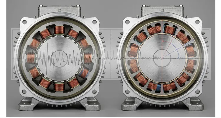
A 48 V auxiliary cooling fan motor on a Class 8 tractor started throwing J1939 error frames at 2,100 engine rpm — only under load, only when ambient temperature crossed about thirty-eight degrees Celsius, and never on the test bench at the Tier 1 supplier. The fan itself was not failing. The fan controller was not logging an overcurrent event. The fault sat one layer deeper: DC-link current ripple from the three-phase stator was coupling into the 24 V and 48 V harness shared with the J1939 physical layer, and the resulting common-mode current was corrupting CAN_H/CAN_L differential signaling just enough to push bit timing outside the sampling window on the ECM side.
That is the frame this discussion belongs in. “Six-phase stator vs three-phase stator” is not an abstract motor-design debate. On a J1939 heavy-duty platform, phase count becomes an electrical noise and bus-integrity decision before it becomes a torque-quality decision. And the engineers who get this wrong usually get it wrong in the same way: they assume six phases automatically means less ripple everywhere, bolt on a dual-three-phase stator, and then discover that the harmonic content moved rather than disappeared. The physical layer underneath all of this is the CAN bus differential signaling standard that J1939 inherits, and it is worth keeping that reference in mind whenever a ripple discussion starts sounding like a motor-only problem.
The failure pattern that actually shows up in the field
The cooling fan case is representative because it combines three conditions that expose phase-count weaknesses on heavy platforms.
First, the motor is PWM-driven from a DC bus shared with sensitive loads. The 48 V auxiliary bus on a modern truck is not a quiet battery line. It feeds the aftertreatment dosing module, the EGR actuator, the cab climate blower, and the J1939 gateway module. Any AC ripple current the fan controller draws from that bus propagates as conducted noise across the shared impedance, and the same mechanism is behind most of the J1939 common-mode noise cases we trace back to alternator ripple frequency on shared auxiliary buses.
Second, the fault is intermittent and load-dependent. A stator with 6.2% torque ripple under rated conditions may look acceptable in a steady-state dyno report. But ripple components that align with the ECM’s CAN sampling clock, or that excite a harness resonance, produce error frames only in specific speed bands. Technicians see an intermittent U-code or a J1939 “error passive” state and replace the fan, the harness, and eventually the ECM — none of which fixes the root cause. Faults that appear in a narrow RPM window are often misread as a repetition-rate phantom calibration timeout because the error counters reset between drive cycles.
Third, the platform carries a J1939 network that was never designed around the EMI signature of the new auxiliary load. J1939-11 specifies shielded twisted pair, but shielding only attenuates radiated coupling. Conducted ripple on the shared 48 V return path bypasses the shield entirely. The failure shows up as corrupted parameter group numbers, missing source addresses, or spurious “not available” values in the diagnostic tool — symptoms that look like a software bug until someone puts a current probe on the DC link.
Why phase count alone does not fix ripple: start with the bus, not the harmonic map
Every six-phase stator inquiry we review eventually reaches the same textbook sentence: a three-phase stator produces a magnetomotive force spectrum with fifth and seventh spatial harmonics, those harmonics interact with the fundamental current, and the result is a sixth-order torque ripple component. A symmetrical six-phase stator — two three-phase winding sets displaced by thirty electrical degrees — can oppose those harmonics in the air gap and largely cancel the sixth-order ripple. That explanation is correct, and it is also not enough to make a platform decision.
The reason is that the platform does not see torque ripple in isolation. It sees DC-link current ripple, common-mode current, and bus voltage disturbance. A motor that looks better on a torque transducer can still inject more conducted noise into the J1939 harness if the ripple spectrum moves into a band where the cable and connector interface are less effective at containing it. This is why the first question on a J1939 platform is not “how many phases” but “where does the ripple land, and what path does it take back to the bus.”
Where the textbook claim breaks down on six-phase stator ripple
The cancellation is conditional, and the condition is rarely stated clearly in supplier datasheets. The six-phase stator advantage depends on how the two winding sets are displaced, how the slots are distributed, and whether the rotor flux path supports the cancellation without introducing a new harmonic of its own. Published work on stator-shifted six-phase truck motors shows the range clearly: a straightforward six-phase conversion without stator shifting reduced torque ripple by only about twenty-two percent compared with its three-phase counterpart, while a stator-shifted design with 24-slot stator-shifted geometry and a seventy-five-degree displacement targeted the seventh harmonic specifically and moved the result into single-digit territory after rotor notching. Those published numbers are useful as a reference point. They are not a substitute for a platform-specific test, because the same winding can produce a different DC-link current ripple spectrum once the inverter carrier scheme and cable interface are included.
The engineering conclusion is uncomfortable but necessary: six phases give you a second harmonic-cancellation degree of freedom. They do not give you a result. If the stator slots, the displacement angle, and the rotor flux barriers are not designed around the specific harmonic you are trying to kill, the ripple simply relocates — often into a higher-order component that is harder to filter and more effective at exciting CAN bus errors. The same lesson applies on the alternator side of the bus, where OEM alternator specification work on J1939 ripple coupling keeps showing that a lower ripple number on one device does not guarantee a cleaner bus.
A six-phase vs three-phase comparison map, with the measurement that decides each row
| Parameter | Three-phase, 12-slot concentrated winding | Six-phase, 24-slot stator-shifted | What to measure before trusting the claim |
| Dominant torque ripple order | 6th electrical | Reduced 5th/7th MMF; residual 12th and higher | Torque spectrum at the worst-case speed and load, not a single peak-to-peak number |
| DC-link current ripple | Baseline | Lower RMS possible, but spectrum shifted upward | DC-link current spectrum from 10 Hz to 5 MHz with the J1939 harness connected |
| Phase current per switch | Higher | Roughly halved per three-phase set | Per-phase di/dt and near-field probe scan around the harness |
| Fault tolerance | Single-point phase loss can mean full torque loss | One three-phase set can limp | Load-step test with one winding set disabled, if the platform requires limp-home |
| Inverter cost and complexity | One three-phase bridge | Two three-phase bridges, shared DC link | Carrier synchronization scheme and DC-link capacitor RMS current at the new spectrum |
The table is not a scorecard. It is a map of where the trade-offs land. A six-phase stator with poor slot design can produce higher high-frequency ripple than a well-designed three-phase machine, because the two inverters interleave and create sum and difference components that a single-bridge topology never generates. The DC-link capacitor sees a different current spectrum, and if the capacitor ESR and ESL are not selected against that spectrum, the bus voltage ripple at the J1939 gateway can actually get worse.
Step-by-step: how to determine whether six-phase is the right answer for a given platform
This is the sequence used when a Tier 1 or OEM asks whether a J1939 auxiliary motor should move from three-phase stator to six-phase stator. It is written as a decision and verification process, not a sales checklist.
Step 1 — Capture the existing DC-link ripple spectrum under the exact J1939 load profile, not a resistive load
Put a high-bandwidth current probe on the 48 V feed to the motor controller and a differential probe across the DC link. Run the motor through the speed and load points where the CAN errors occur. Record the ripple current spectrum from 10 Hz to 5 MHz. The question is not “how much ripple”; it is “which frequencies carry the energy that aligns with the J1939 bit rate and the harness resonant modes.” A 250 kbps J1939 bus has a bit time of four microseconds; ripple components in the tens to hundreds of kilohertz range are the ones most likely to corrupt sampling. Mark the harness resonant frequencies on the same plot, measured with a vector network analyzer or an impedance analyzer, so the motor spectrum and the cable spectrum are read together. If a differential probe is not available on the bench, the practical workaround is described in how to measure CAN ripple without a differential probe, though a true differential measurement remains the reference method.
Step 2 — Separate differential-mode ripple from common-mode current
Use a current probe on the 48 V positive and return conductors simultaneously, or a Rogowski coil around both. Common-mode current is the component that flows through the chassis and the shield, and it is the component most often responsible for J1939 error frames when the bus shielding is intact but the ground reference is moving. If common-mode current dominates, a phase-count change alone will not fix the problem — the controller’s dv/dt and the motor’s parasitic capacitance to frame are the primary levers. This step decides whether the stator is the main problem or a secondary contributor. A cable asymmetry of even a few percent can convert differential ripple into common-mode noise, which is why cable asymmetry and common-mode noise on a twelve percent mismatch deserves a look before the motor is blamed.
Step 3 — Model the harmonic cancellation of the candidate six-phase winding before cutting laminations
For a stator-shifted design, the displacement angle between the two three-phase sets is a design variable. The published truck-motor study used seventy-five-degree displacement with twenty-four slots to minimize the seventh harmonic; a thirty-degree symmetrical six-phase displacement targets the fifth and seventh differently. Ask the stator supplier for the winding function harmonic spectrum, not just the fundamental turns count. If the supplier cannot produce a slot-by-slot MMF harmonic table, the six-phase claim is unverified. On a J1939 platform, an unverified harmonic claim is not a design input; it is a prototype risk.
Step 4 — Verify the DC-link capacitor and bus filter against the new ripple spectrum, not the old one
A six-phase stator can reduce low-order torque ripple while increasing ripple energy at the switching frequency and its sidebands. The DC-link capacitor must be selected for the RMS current at those frequencies. This is where many “six-phase upgrade” projects fail late: the motor ripple improves on the torque transducer, but the bus voltage ripple at the J1939 gateway gets worse because the capacitor was carried over from the three-phase BOM. The capacitor case temperature rise at the new ripple spectrum is part of the validation, not a purchasing detail.
Step 5 — Run the J1939 error-counter test, not just the torque-ripple test
Connect a CAN analyzer that logs error frames, error passive events, and bus load over the full duty cycle. The pass criterion is not “no error frames on a static bench.” It is “no increase in error-counter increments across the temperature and load profile where the original fault appeared.” Torque ripple and bus-integrity are related but not interchangeable; a motor with low torque ripple can still inject enough common-mode current to trip the CAN controller’s error counters. A structured diagnostic workflow, such as the J1939 calibration fault troubleshooting flowchart, helps separate a genuine bus-integrity problem from a calibration event that only looks like one.
Step 6 — Confirm the result with a salt-spray-exposed harness and connector interface
On a heavy-duty platform, the ripple path includes the motor-to-controller cable and the connector backshells. If the six-phase stator design changes the number of power conductors, the connector pinout and shield termination change as well. A design that looks clean on a bench harness can degrade after salt spray exposure because shield-to-shell impedance rises at the corroded interface. This is why the validation plan should include a salt-spray-conditioned cable assembly measured for transfer impedance, not just a visual inspection after the chamber. The salt spray test belongs in the ripple discussion because the shield termination is part of the common-mode path, and a corroded termination changes the path without changing the motor. Field data from salt spray testing on OBD harnesses in coastal fleets shows how quickly a clean bench result diverges from a conditioned assembly.
Five mistakes that show up repeatedly in six-phase evaluations
- Mistake one: treating “six-phase” as a single topology. A symmetrical thirty-degree displacement, a dual-three-phase sixty-degree displacement, and a stator-shifted seventy-five-degree displacement asymmetrical winding are three different harmonic machines. They cannot be compared under one datasheet heading. A supplier that quotes “six-phase torque ripple” without naming the displacement angle is telling you nothing usable.
- Mistake two: measuring torque ripple on a rigid dyno and assuming bus ripple follows. A stiff dyno absorbs torque oscillations that a vehicle driveline would reflect back into the motor. The DC-link current ripple spectrum on a dyno can look far cleaner than the spectrum on a chassis dynamometer or in a vehicle because the mechanical boundary condition changes the current harmonics. Always correlate the torque transducer data with DC-link current data taken simultaneously.
- Mistake three: overlooking the second three-phase inverter’s switching interaction. Two three-phase bridges on a shared DC link interleave, and the interleaving angle changes the DC-link ripple cancellation. A six-phase stator motor driven by two bridges with uncoordinated PWM carriers can produce more low-frequency bus ripple than a single three-phase bridge, because the difference in switching instants creates a beat component. The controller’s carrier synchronization scheme is part of the ripple solution, not an afterthought.
- Mistake four: using the phase-count change to compensate for a grounding or shielding defect. If the original three-phase stator installation had a missing shield termination or a ground loop between the motor frame and the chassis, six phases will not fix the resulting common-mode current. It may change the frequency at which the symptom appears, which is worse — it makes diagnosis harder without removing the root cause. Fix the installation first, then evaluate the topology. Ground offsets as small as a few hundred millivolts are enough to break communication, as documented in the zero point three volt ground offset on a J1939 backbone case.
- Mistake five: accepting a PPAP package that does not include the harmonic spectrum and salt-spray-conditioned cable data. A PPAP that contains only dimensional reports and a torque-speed curve is incomplete for a ripple-sensitive J1939 application. Under IATF 16949, PPAP is meant to demonstrate that all design and specification requirements are met. If the specification includes a bus-error criterion, the PPAP evidence must include the test that demonstrates it, not a generic motor performance report. The evidence list we expect for a PPAP Level 3 documentation package on OBD cable assemblies applies here almost unchanged.
What “fixed” actually looks like
A successful six-phase conversion on a J1939 platform passes three independent checks.
The torque-ripple check: the dominant ripple order moves out of the band that excites the driveline or the mount resonance, and the peak-to-peak torque oscillation at the worst-case operating point is demonstrably lower than the three-phase baseline under the same thermal and load conditions. A single number without the operating point is not evidence.
The DC-link current check: the RMS ripple current in the frequency band that couples to the J1939 harness is lower, and the DC-link capacitor case temperature rise at that ripple is within its rated limit. A design that reduces low-frequency ripple but overheats the capacitor at the switching frequency has not solved the platform problem.
The bus-integrity check: the J1939 error frames counters remain flat across the temperature and load profile that originally triggered the fault. This is the only check that speaks directly to the customer symptom. It should be logged over multiple thermal cycles, not a single steady-state run. A pass criterion built around error counters is the same logic we use in a ripple-to-bus coupling test for PPAP on J1939 alternators, and it is the only check that survives a change of test cell.
When these three checks pass, the phase-count decision has been validated against the platform, not against a motor-only specification. That is the difference between a datasheet improvement and a production fix.
What this means for OEM sourcing and custom stator programs
The practical consequence is that a six-phase stator for a J1939 heavy-duty auxiliary load cannot be treated as a catalog variant of a three-phase stator. The displacement angle, the slot count, the winding function, and the rotor flux path are coupled. Changing the phase count without re-optimizing those variables can move the ripple problem rather than solve it.
Start with the symptom, not the phase count
That is why the sourcing conversation should begin with the platform symptom, not the phase count. A supplier who asks “what bus errors are you seeing, at what speed and load, and what does the DC-link current ripple spectrum look like” is positioned to give a useful answer. A supplier who quotes “six-phase, lower ripple” without asking those questions is selling a topology, not an engineering result. The same questioning discipline appears in our audit checklist for custom OBD cable suppliers, where the seven questions are designed to expose whether a supplier is quoting a part number or a verified result.
For programs moving toward production, the evidence package matters as much as the prototype. Under an IATF 16949 framework, the PPAP submission should include the harmonic spectrum of the as-built winding, the DC-link ripple test at the worst-case J1939 load point, and the salt-spray-conditioned cable assembly transfer impedance data. These are the documents that let an OEM release the part without re-validating the bus integrity on every vehicle variant.
What belongs in the PPAP package for a heavy-duty auxiliary motor stator
A PPAP package for this kind of part should read like a test record, not a brochure. The harmonic spectrum report should show the slot-by-slot winding function and the as-built displacement angle. The DC-link ripple test should name the operating point, the bus voltage, the capacitor part number, and the J1939 error frames counter result from the same run. The salt-spray-conditioned cable data should include transfer impedance before and after exposure, because the shield termination is part of the common-mode current path. If the package does not contain those three items, the OEM is being asked to trust a motor datasheet that may not contain the test that proves the fix.
We build stators and cable assemblies for heavy-duty auxiliary motor stator and traction motor programs under ISO 9001, ISO 14001, and IATF 16949, with PPAP documentation available from prototype through production. Our factory has more than twenty-one years of direct factory manufacturing experience, and production follows 5S management with a climate-controlled warehouse. Every lot passes a four-step quality inspection, and wound assemblies are 100% tested before shipment. RoHS-compliant full-plastic connector designs are available, and CE, UL, and REACH documentation can be supplied where the connector and cable assembly scope requires it, including the UL 94 V-0 jacket specification for diagnostic cables. Salt spray testing is performed on wound assemblies and cable interfaces, not just bare laminations, because the ripple path includes the connector and shield termination. OEM customization covers logo, brand, length, color, AWG, lead length, connector interface, winding displacement angle, slot count, and lamination stack — the parameters that actually determine whether a six-phase stator design reduces bus noise or merely changes its frequency.
If you are evaluating this on a live platform
The fastest path to a useful answer is a short technical exchange around the symptom, not a request for a quotation. Send the J1939 error frames signature, the operating point where it appears, and the existing DC-link current ripple spectrum if you have it. We can tell you whether the phase-count change is likely to address the mechanism, or whether the problem sits in the grounding, the capacitor, or the PWM carriers scheme before any stator is cut.
WhatsApp: Chat with Linda on WhatsApp at https://api.whatsapp.com/send/?phone=8617307168662&text=Need+Help%3F+Chat+linda+WhatsAPP&type=phone_number&app_absent=0 — include “six-phase J1939 ripple” in the first message so it routes to the engineering thread.
Contact page: https://obd-cable.com/contact/ — use the message field for the bus-error description and the operating point; a short symptom note is more useful than a full RFQ at this stage.
FAQ
Does a six-phase stator always produce lower torque ripple than a three-phase stator?
No. A symmetrical six-phase winding can cancel the fifth and seventh MMF harmonics that drive sixth-order torque ripple, but published work on heavy-truck motors shows that a straightforward six-phase conversion without stator shifting reduced torque ripple by only about twenty-two percent. The result depends on displacement angle, slot count, and rotor flux path.
Can six-phase reduce J1939 error frames directly?
It can, but not because of torque ripple alone. The mechanism is the DC-link current ripple spectrum and the common-mode current that couples into the shared 48 V harness. A six-phase design that reduces low-frequency bus ripple while increasing switching-frequency ripple can leave J1939 error counters unchanged or worse. The bus-integrity test is the only direct verification.
What displacement angle should a six-phase heavy-duty stator use?
There is no universal answer. A thirty-degree symmetrical displacement targets the fifth and seventh harmonics differently from a seventy-five-degree displacement stator-shifted design that specifically minimizes the seventh harmonic with a twenty-four-slot, ten-pole layout. The angle should be selected against the harmonic that dominates the platform symptom, not copied from a generic reference.
Why did the fan motor fault appear only at high ambient temperature?
Temperature changes the DC-link capacitor ESR and the cable shield-to-shell impedance. A ripple path that is marginally stable at twenty-five degrees can cross the J1939 error threshold at thirty-eight degrees because the capacitor’s impedance rises and the shield termination degrades. This is also why a bench test at room temperature can pass while the vehicle fails, and why hot and cold termination resistance shift on J1939 buses is part of the same thermal story.
Is PPAP overkill for an auxiliary motor stator?
Not when the platform symptom is a bus error. PPAP is the mechanism that forces the harmonic-spectrum and bus-integrity evidence into the release package. Without it, the OEM is relying on a motor datasheet that may not contain the test that proves the fix.
What role does salt spray play in a ripple problem?
Salt spray degrades the shield-to-connector-shell interface. A six-phase stator may change the number of power conductors and therefore the connector pinout. If the shield termination is not tested after salt spray, the common-mode current path can degrade in the field even though the motor passes a bench ripple test.
Can a six-phase motor use two standard three-phase inverters?
Yes, and that is one of its practical advantages for heavy-duty platforms. But the two bridges must have coordinated PWM carriers. Uncoordinated carriers can produce a beat-frequency DC-link ripple component that a single three-phase bridge never generates, which is one reason the controller and stator must be evaluated together.
What data should accompany a six-phase stator RFQ?
The J1939 error frames signature, the operating point, the existing DC-link current ripple spectrum, the harness shield termination drawing, and the target bus-error criterion. A torque-speed curve alone does not allow the supplier to determine whether the phase-count change addresses the mechanism.
How do you know whether the problem is torque ripple or common-mode current?
Measure both. A current probe on the DC-link positive and return, plus a Rogowski coil around both conductors, separates differential-mode from common-mode current. If common-mode dominates, phase count is secondary to grounding, dv/dt, and shield termination. If differential-mode ripple in the J1939-sensitive band dominates, the stator harmonic design becomes the primary lever.
Does a lower torque-ripple number guarantee a quieter J1939 bus?
No. Torque ripple and bus ripple share a common source in the MMF harmonics, but they are filtered differently by the mechanical system and the DC-link impedance. A motor with low torque ripple can still inject conducted noise if the capacitor and cable interface are not selected against the resulting current spectrum. The bus-integrity test is the release criterion that closes the gap.
