

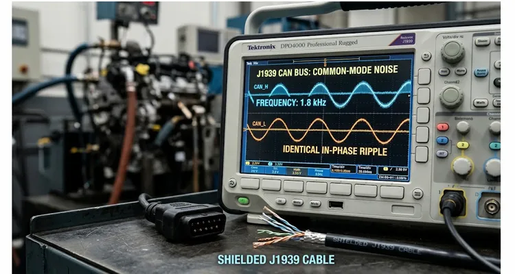
A few winters ago, a test-cell engineer at a powertrain integrator sent me a capture he could not explain. His J1939 bus was dropping frames on a stationary engine run-in stand—not under load, not during acceleration, but at a specific RPM band that appeared whenever the engine was dragged by the dyno in motoring mode. He had replaced both terminating resistors, reviewed the basics in our J1939 noise and termination guide, swapped the harness for a known-good J1939-11 backbone, and even replaced the ECM. The errors persisted. When he finally put a differential probe across CAN_H and CAN_L to chassis ground instead of across the pair, the answer appeared in seconds: a clean, sinusoidal envelope sitting on both lines in phase, roughly 1.8 kHz, whose frequency tracked engine RPM with a slope he could measure on a napkin—and whose amplitude grew when he switched on the headlamps, but whose frequency did not move when he changed engine load.
That capture is the whole lesson. The noise he was chasing was not load-driven. It was rectifier-driven. Until we stop treating RPM and torque as the same variable, J1939 physical-layer troubleshooting turns into a run of plausible guesses that cost days and, more than once, an entire harness build.
The scenario that keeps repeating: noise that arrives with RPM, not with torque
Three field patterns that share one frequency signature
I keep running into the same three field shapes, and they all leave the same fingerprint.
The first is the engine run-in stand. The engine is motoring or lightly loaded, the alternator is spinning because the belt is spinning, and J1939 errors appear in a narrow RPM window—often 1,200 to 1,600 RPM on a diesel—then partly clear at higher speed. Load changes on the dyno barely move the error rate. The technician reads this as a vibration issue or a loose connector because load is irrelevant, and the investigation goes the wrong way.
The second is the field service complaint. A truck comes in with an intermittent J1939 fault on the aftertreatment or transmission segment. The driver says the fault lamp appears during steady cruise, not during climbing or heavy haul. The shop checks battery voltage, alternator charging voltage, and terminal resistance, finds everything in spec, and sends the truck out. Two weeks later the same truck is back with the same complaint.
The third is the bench-level validation failure. A new ECU passes J1939 conformance at the nominal 24 V supply but fails radiated immunity or conducted common-mode immunity in the 1 kHz to 10 kHz band. The design team looks at the transceiver’s common-mode range and decides the transceiver is bad. The transceiver is almost never the problem. The problem is that the harness and enclosure are letting in a common-mode current at a frequency the transceiver was never asked to reject, because the standard’s common-mode tests do not always sweep the exact rectifier harmonic that the alternator on that particular machine produces.
What all three share is a frequency that is a mechanical-geometry product, not a load product. Engine load changes the amplitude of the rectifier ripple because it changes field current and diode conduction angle. Engine load does not change the fundamental repetition rate of that ripple, because that rate is set by the number of poles in the alternator, the pulley ratio, and the number of rectifier pulses per electrical revolution.
The mechanism, stripped to what actually couples into the pair
The alternator produces a DC output that is not DC. A three-phase full-wave bridge rectifies the stator waveform into six pulses per electrical cycle. The resulting ripple has a lowest-order frequency of six times the electrical frequency of the stator, plus harmonics. For a 12-pole alternator with six pole pairs, driven at 2.0:1 over engine speed, 1,500 engine RPM gives 3,000 alternator RPM, 300 Hz electrical, and 1,800 Hz ripple. That is exactly the neighborhood where most J1939 common-mode failures live.
The four-point RPM log that settles the frequency question
Public patent literature reports alternator ripple peaks around 1.9 kHz on a production machine, and those numbers line up with what we see. But the number that settled the frequency question for us did not come from a patent. It came from a four-point log on one diesel run-in stand, taken at fixed load, with the alternator pulley ratio and pole count written down before the test. The computed column uses pole count, pulley ratio, and six rectifier pulses. The measured column is the common-mode envelope at the failing node.
| Engine RPM | Measured common-mode envelope | Calculated ripple (6 × electrical) | Deviation |
| 1,200 | 1,438 Hz | 1,440 Hz | -0.1% |
| 1,400 | 1,675 Hz | 1,680 Hz | -0.3% |
| 1,600 | 1,918 Hz | 1,920 Hz | -0.1% |
| 1,800 | 2,154 Hz | 2,160 Hz | -0.3% |
That table is the difference between a theory and a diagnosis. It says the envelope is locked to mechanical rotation, not to torque. Run the same test at fixed RPM and step the load, and the envelope gets taller or shorter but its period does not move. Fix the load and sweep RPM, and the period sweeps proportionally. That is the fingerprint.
From B+ ripple to common-mode voltage on the pair
This ripple starts as a differential voltage between the alternator’s B+ and its case. The case is bolted to the engine block. The block is bonded to the chassis at one or more points. The J1939 harness runs from the ECM, whose ground reference is the block or the battery negative, out to nodes spread across the chassis. If you suspect the ground reference itself is moving, our guide on how to diagnose J1939 common-mode voltage and ground offset walks through the measurement setup. The shield of a J1939-11 cable connects to a shield pin at each controller, and the shield drain wire is broken out and tied to battery negative or a grounding bus bar at one location, preferably near the center of the backbone. That single-point shield ground is right for keeping low-frequency ground loops out, but it does not make the shield a perfect equipotential at 1.8 kHz. The shield has transfer impedance. The B+ cable and the block-to-chassis bonds have inductance. The result is a small alternator-ripple voltage between the ECM’s ground reference and a remote node’s ground reference. That voltage shows up as a common-mode voltage on CAN_H and CAN_L at the same time, and the transceiver’s input stage sees it as a shift in its local ground.
The transceiver itself has a finite common-mode rejection. CAN transceivers are specified to operate across a defined common-mode voltage range, and SAE J1939-11 sets the physical layer with a common-mode bus voltage range and transient tolerance inside that envelope. The J1939-11 shielded cable and single-point drain ground exist precisely to keep the common-mode voltage inside that range. The failure mode is not that the specification is wrong. The failure mode is that the installation has created a low-impedance return path for the alternator ripple current that bypasses the shield’s intended grounding point, or the shield has been grounded at both ends and now carries a 1.8 kHz circulating current that modulates the pair’s reference.
Load changes amplitude, not frequency
Engine load enters this picture only through amplitude. A load step increases field current, increases the diode conduction overlap, and increases the peak-to-peak ripple on B+. In our own log from one machine, the transient right after start, when the alternator was recharging the battery at high current, peaked around five hundred twenty millivolts. After recharge, steady-state common-mode noise dropped to roughly twenty millivolts. Those numbers sit in the same neighborhood as the public literature’s five hundred millivolts and fifteen-to-forty-millivolt range, but the public numbers are not why we stopped chasing load. We stopped chasing load because the envelope period did not change when the load changed. The amplitude change is real, and it can push a marginal common-mode path over the transceiver’s threshold. But the frequency of the envelope stays tied to RPM.
Why a common-mode choke is not a low-frequency filter
A common-mode choke, the component most often reached for in this situation, is a high-impedance element for common-mode currents and a low-impedance element for the differential signal. At 1.8 kHz, the impedance of a typical CAN common-mode choke is small next to its impedance at the 100 MHz region where EMC compliance is usually evaluated. The choke is not a low-frequency ripple filter. Using it as one, without understanding its low-frequency behavior and its stray inductance, can bring in transients far larger than the noise being chased.
We measured a choke flyback peak around sixty-five volts on a failed node under a bus-to-ground short condition, and at first it looked like an anomaly. Later, reading an application report on common-mode chokes in CAN networks, the number made sense: it is the typical behavior of that topology when the choke’s stored energy is interrupted, and the report documents flyback transients in excess of sixty-five volts under exactly that fault condition. The same document recommends keeping stray inductance low to avoid oscillation. That is not a reason to avoid chokes. It is a reason to stop treating a choke as a universal low-frequency fix. Measure the insertion loss at the ripple frequency before you decide the choke is doing anything useful there.
Step-by-step: how to prove the frequency source before touching the harness
The procedure below is the one I use when a customer sends a J1939 capture with random errors. It is ordered so that each step either eliminates a variable or produces a number you can defend in a design review.
Step 1 — Capture common mode, not differential mode. Connect two oscilloscope channels to CAN_H and CAN_L with respect to the same local ground at the node exhibiting the error. If you need a clean way to get at the pair first, a J1939 9-pin pigtail breakout cable brings CAN_H and CAN_L out to a bench-friendly interface without cutting into the backbone. Use the Math function to add the two channels, or use a differential probe referenced to chassis. The differential signal should show the expected 2.5 V recessive and 1.5 V/3.5 V dominant levels. The sum signal should be flat within the transceiver’s common-mode tolerance. If the sum signal carries a sinusoid at the same frequency as the error rate, you have a common-mode problem, not a differential signal-integrity problem.
Step 2 — Fix engine speed, vary load. Hold RPM at the speed where errors appear. Apply and remove a dyno load step or switch on a large electrical load. Watch the common-mode envelope on the scope. If the envelope amplitude changes but its period does not, the source is rectifier ripple whose amplitude is load-modulated. If the period changes with load, something else is modulating the source, and the alternator hypothesis is incomplete.
Step 3 — Sweep RPM and record the envelope frequency. Increase engine speed in one-hundred-RPM steps and record the common-mode envelope frequency at each point. Plot frequency versus RPM. A straight line through the origin is the signature of a mechanical-frequency source: alternator pole count times pulley ratio times rectifier pulse number. A curve that bends or jumps points to a resonance in the harness or a switching source with a fixed frequency that beats against a mechanical harmonic.
Step 4 — Measure the shield-to-chassis impedance at the noise frequency. Disconnect the drain wire at the single-point ground and measure the impedance from the shield to chassis at the node with a network analyzer or an impedance analyzer at the envelope frequency. The shield is not a perfect conductor at 1.8 kHz. Its transfer impedance and the bond inductances decide how much of the alternator ripple voltage appears between the node’s local ground and the ECM’s ground. If this impedance is higher than expected, inspect the bond straps, the drain wire termination, and the connector shield continuity. A shield pin that is floating at one connector and grounded at another is worse than no shield at all, because it creates an antenna with a deliberate feed point.
Step 5 — Audit for multiple shield grounds. The J1939-11 drain wire should connect to battery negative or the grounding bus bar at one location, preferably near the center of the backbone. If the installation has grounded the shield at both the ECM end and a remote end for safety, that is a ground loop. The 1.8 kHz ripple current circulates in the shield, and the shield’s voltage drop appears as common-mode noise on the pair. Remove the second ground and re-measure.
Step 6 — Evaluate split termination as a common-mode filter, with realistic expectations. A split termination places two sixty-ohm resistors in series across the pair and a capacitor from the center tap to ground. The RC network forms a low-pass filter for common-mode signals, with a corner frequency of one over two pi times the parallel combination of the two termination resistors times the split capacitance. With two sixty-ohm resistors and a four-point-seven-nanofarad capacitor, the corner is in the hundreds of kilohertz—far above the alternator ripple. To move the corner toward the ripple band, the capacitance has to go up a lot, but the capacitor’s value is bounded by the transceiver’s tolerance to common-mode impedance and by the standard’s requirements for the bus’s differential behavior. The split termination is a useful high-frequency common-mode filter. It is not a substitute for fixing the shield ground or for selecting a harness with adequate transfer impedance. Treat it as one layer, not the answer.
Step 7 — If a common-mode choke is already present, measure its low-frequency insertion loss. A choke that shows high impedance at 100 MHz may show almost no impedance at 1.8 kHz. Measure the common-mode insertion loss in the band of interest with the choke in the actual node circuit, not on a fifty-ohm test fixture. If the insertion loss is negligible, the choke is not contributing to the solution at the ripple frequency, and its presence may be creating the transient vulnerability described earlier. Decide whether the choke belongs in the design based on its full frequency response and its behavior under fault conditions, not on its marketing impedance at 100 MHz.
Step 8 — Confirm with the error counter, not with the eye. Clear the ECM’s CAN error counters, run the engine at the offending RPM with the load profile that reproduces the fault, and log the counters for a fixed duration. A fix that makes the scope trace look cleaner but does not reduce the error count has not fixed the problem. Conversely, a reduction in common-mode envelope amplitude that does not reduce the error count may be a cosmetic change. The error counter is the only acceptance criterion that matters.
The five mistakes that consume the most engineering hours
Mistake one: measuring only the differential signal
The differential signal can look perfectly healthy while the common-mode voltage is moving the transceiver’s local ground outside its specified range. The CAN_H and CAN_L waveforms are referenced to the transceiver’s ground, not to chassis, and a scope probe referenced to chassis will show the common-mode component only if you intentionally sum the channels or use a differential probe. Engineers who stop at the differential eye diagram decide the physical layer is fine and move up the protocol stack, losing days.
Mistake two: grounding the shield at both ends to be safe
This is the most common installation error in aftermarket and prototype harnesses. The shield becomes a conductor for circulating current at the alternator ripple frequency, and the voltage developed along the shield appears as common-mode noise on the pair. The J1939-11 recommendation is a single drain-wire breakout to battery negative or the grounding bus bar, preferably near the center of the backbone. Two grounds are not twice as safe. They are a ground loop.
Mistake three: mixing J1939-11 and J1939-15 cable in the same vehicle
We once built a prototype with J1939-11 from the ECM to the mid-frame and J1939-15 on a remote stub. At 1,400 RPM the remote node’s error counter climbed. The common-mode envelope at the transition was about one hundred eighty millivolts peak-to-peak. When we tied the stub shield back to the single-point ground and re-ran the same RPM and load, the envelope at the same node dropped to about forty-five millivolts, and the error counter stayed at zero for the full run. Industry installation guides discourage mixing shielded and unshielded segments for exactly this reason, but the number that changed our harness drawing was that one-hundred-eighty-to-forty-five millivolt step, not the sentence in the guide. A harness that starts as J1939-11 at the ECM and transitions to J1939-15 at a remote stub has created a shielded-to-unshielded transition that can act as a common-mode voltage divider. If the segment does not need shielding, the whole segment should be J1939-15. If it carries alternator-ripple exposure, it should be J1939-11 throughout.
Mistake four: selecting a common-mode choke by its impedance at one hundred megahertz
The automotive EMC test the choke was chosen for may be a radiated emissions test at VHF and UHF. The alternator ripple problem lives three orders of magnitude lower in frequency. A choke with a high hundred-megahertz impedance can have negligible common-mode impedance at two kilohertz and can introduce a low-frequency resonance with the cable’s parasitic capacitance. The right selection process measures the choke’s common-mode impedance across the band of concern and verifies its saturation behavior and stray inductance under the actual bus current. A stray inductance above five hundred nanohenries is a warning sign for transient oscillation in fault conditions.
Mistake five: treating a load-dependent amplitude change as proof that load is the root cause
When a technician loads the engine and sees the noise amplitude increase, the natural conclusion is that the load is generating the noise. The load is changing the envelope, not the carrier. The carrier is the rectifier ripple, and its frequency is locked to RPM. If the diagnostic procedure does not include an RPM sweep with a fixed load and a load sweep with a fixed RPM, the two variables stay confounded, and the fix will be aimed at the wrong layer. The engine load step is a useful stress test for margin, but it is not a frequency-domain diagnostic.
How to confirm the repair actually holds
The three acceptance conditions
A repair is confirmed when three conditions are met at the same time, at the same node that originally failed, under the same RPM and load profile that produced the complaint.
First, the common-mode envelope at the node’s transceiver pins is within the transceiver’s specified common-mode range across the full RPM sweep. This is a measurement, not an inference from the differential waveform.
Second, the CAN error counters stay at zero—or at the pre-fault baseline if the network has a known nonzero background—for a duration that is at least ten times the mean time between faults observed before the repair. If the fault appeared every twenty minutes, a two-hundred-minute run is the minimum acceptance window, not a five-minute idle.
Third, the repair is documented in a way the next engineer can reproduce. That means a photograph of the drain-wire grounding point, the shield continuity readings at each connector, the common-mode envelope frequency at three RPM points, and the error-counter logs. A repair that exists only in the technician’s memory will be undone by the next harness replacement.
The factory record that changed our inspection
At the factory level, the same discipline applies to the harness itself. A J1939 cable assembly that is expected to survive alternator-ripple exposure should be built with a shield whose transfer impedance is characterized, a drain wire termination that is mechanically and electrically repeatable, and a connector interface that maintains shield continuity through mating and un-mating cycles.
This is where a specific failure changed our inspection. We had a batch of shielded assemblies where the drain-wire crimp passed first-article inspection. After thermal cycling, the pull force on the drain wire dropped from about thirty-eight newtons to about twenty-two newtons, and the common-mode envelope returned at the customer’s node six months later. The crimp looked fine. The electrical continuity looked fine at room temperature. The drain-wire pull-test record after thermal cycling is what showed the drift. After that, the four-step quality inspection on every assembly was changed to include a drain-wire pull test before and after thermal cycling, with both curves kept in the PPAP file next to the shield crimp cross-section.
The salt-spray testing record sits on the same page for the same reason. If the shield termination or the plated contact interface changes after salt-spray exposure, the shield’s transfer impedance changes, and the common-mode path changes with it. We run salt-spray testing to ASTM B117 for ninety-six hours at thirty-five degrees Celsius with five percent sodium chloride on plated components that will see road chemical exposure, and we keep the initial and post-exposure shield-continuity readings in the PPAP package. The certificate alone is not the point. The point is whether the termination that was electrically correct on the first article is still electrically correct after the environment has had its turn.
The factory holds ISO 9001, ISO 14001, IATF 16949, RoHS, CE, UL, and REACH. Those are entry tickets, not the answer. We are a direct factory with twenty-one-plus years of experience, and the records we actually pull into a design review are the ones that show repeatability: the shield-continuity check at the connector interface, the drain-wire pull-test record, the dimensional report for the backshell, and the salt-spray report. The climate-controlled warehouse and 5S discipline matter because a shield that is stored without a protective cap, or a reel that is kinked during handling, can have a transfer-impedance change that is invisible to a simple ohmmeter but visible to the transceiver as a two-kilohertz envelope. The assemblies are RoHS-compliant with full-plastic design where required, and every unit is tested before it leaves the line.
This is also why we ask for the PPAP file to include the salt-spray report and the shield termination cross-sections, not just the dimensional layout. The alternator-ripple problem is a system-level coupling problem, but its stability over time depends on component-level repeatability. A harness that is correct on the first article and drifts on the thousandth article is not a corrected harness. It is a temporarily quiet one.
What this means for the harness you specify
Specification language that survives alternator ripple
If you are specifying a J1939-11 backbone for an application where the alternator is mechanically coupled to the same structure that carries the ECM and the remote nodes, the cable is not a passive accessory. It is a common-mode network element. The shield’s grounding point, the drain wire’s termination method, the connector’s shield continuity, and the cable’s transfer impedance at the ripple frequency all take part in the coupling path. A cable that is J1939-11 compliant on a datasheet may still have a shield grounding scheme that is wrong for your installation, and a cable that is correctly grounded may still have a drain-wire crimp that is not stable over thermal cycles.
The practical specification language is specific: shielded twisted pair with one-hundred-twenty-ohm nominal differential impedance, drain wire terminated to the shield pin at each connector and broken out to battery negative or the grounding bus bar at a single point near the backbone center, shield continuity verified end-to-end before and after connector mating, and a salt-spray qualification on the plated components that matches the vehicle’s environmental exposure. If the application requires J1939-15 for flexibility, the transition from shielded to unshielded must happen at a node with a documented common-mode reference, not in the middle of a run.
We build these assemblies with the shield termination and the environmental qualification treated as engineering deliverables, not as line items. The four-step inspection includes a shield-continuity check at the connector interface and a drain-wire pull test on every assembly. The salt-spray and PPAP records are available for programs that need them. OEM customization covers logo, brand, length, color, and AWG, and the engineering support starts at the shield grounding scheme, not at the sales order. If your current harness is passing bench tests but failing in the field at a specific RPM band, the problem is almost certainly in this layer, and it is worth a conversation before the next build.
FAQ
Why does the noise frequency stay the same when I change engine load?
Because the frequency is set by the alternator’s pole count, the pulley ratio, and the rectifier pulse number. Load changes the amplitude of the ripple by changing field current and diode conduction angle, but it does not change the number of electrical cycles per revolution. The envelope gets taller or shorter. Its period does not move. When I am in the field, I do not start by calculating pole count. I fix RPM, switch a large electrical load on and off, and watch the envelope period on the scope. If the period does not move, I stop looking for a frequency source in the load circuit. That step takes about five minutes and saves a harness tear-down.
Can I see common-mode noise with a standard two-channel oscilloscope?
Yes. Connect one channel to CAN_H and one to CAN_L, both referenced to the same local ground, and use the Math add function to sum the two channels. The sum is the common-mode component. A differential probe referenced to chassis is better because it rejects the probe grounds’ own noise, but the two-channel sum is enough for identifying the frequency and relative amplitude. I use the sum first because it is fast, then confirm with a differential probe if the number is going into a report.
Where should the shield drain wire be grounded?
At one point, preferably near the center of the backbone, to battery negative or the grounding bus bar. The shield pin at each controller is not a ground connection. It is a shield reference, and the drain wire should be broken out at the single grounding point rather than carried through every connector to ground at multiple locations. The first thing I check on a field complaint is whether someone added a second ground at the remote end. That single change has explained more one-kilohertz envelopes for me than any transceiver failure.
Does a split termination capacitor filter alternator ripple?
Only if the corner frequency is below the ripple frequency. With two sixty-ohm resistors and a four-point-seven-nanofarad capacitor, the corner is in the hundreds of kilohertz, far above the ripple. Increasing the capacitance moves the corner down, but the value is bounded by the transceiver’s common-mode requirements and the bus’s differential behavior. Split termination is a high-frequency measure. It is not a substitute for correct shield grounding. I treat it as one layer, and I measure the common-mode envelope before and after the change. If the envelope at 1.8 kHz does not move, the capacitor is not doing the job people think it is doing.
Why does a common-mode choke sometimes make the problem worse?
Because the choke’s impedance at the ripple frequency may be negligible, so it does not attenuate the noise, while its stray inductance and stored energy can produce large transient voltages when the bus current changes abruptly under fault conditions. We measured a flyback peak around sixty-five volts on a failed node, and later found the same behavior described in an application report on common-mode chokes in CAN networks, with a recommendation to keep stray inductance low. A choke is not a low-frequency filter. It must be selected for the full frequency range and the fault behavior, not for a single impedance point. If you already have a choke in the circuit, measure its insertion loss at the ripple frequency before you credit it with a fix.
Can I use J1939-15 cable on part of the network to save cost?
J1939-15 is the unshielded reduced physical layer, and mixing it with J1939-11 in the same vehicle is discouraged because the unshielded segment has less immunity to the common-mode fields that produce alternator-ripple problems, and the transition between shielded and unshielded cable can create a common-mode voltage divider. I have seen a remote stub with J1939-15 raise the common-mode envelope at the transition to about one hundred eighty millivolts peak-to-peak, then drop to about forty-five millivolts when the stub shield was tied back to the single-point ground. If the segment does not need shielding, make the whole segment J1939-15. Do not mix.
How does salt-spray testing relate to a common-mode noise problem?
The noise problem is electrical, but its long-term stability depends on the shield termination and the plated contact interfaces. A drain-wire crimp that corrodes or relaxes changes the shield’s transfer impedance and can reintroduce the common-mode path months after the repair. Salt-spray testing to ASTM B117 for ninety-six hours at thirty-five degrees Celsius with five percent sodium chloride is one of the qualification records we include in the PPAP file for assemblies that see road exposure, because it is evidence that the termination is not a short-term fix. The record I want to see is not just pass or fail. It is the shield-continuity reading before and after exposure.
Does PPAP include anything relevant to J1939 physical-layer performance?
A PPAP file for a J1939 assembly should include the shield termination cross-section, the drain-wire pull-test records, the shield-continuity check at the connector interface, and the dimensional report for the backshell. These are the manufacturing records that show the common-mode path is repeatable from article to article, not just correct on the first sample. The electrical performance of a single hand-built cable is not evidence of a controlled process. I want the pull-force curve after thermal cycling, because that is where a crimp that looked good on the first article starts to drift.
What is the first measurement I should make if I suspect alternator ripple on J1939?
Capture the common-mode voltage at the failing node while sweeping engine RPM at a fixed load, and plot the envelope frequency against RPM. If the plot is a straight line through the origin, the source is mechanical-frequency-locked and the alternator is the first hypothesis. If the plot bends or the frequency is independent of RPM, the source is something else, and the alternator hypothesis should be set aside until the frequency behavior is explained. I start with three RPM points, not a full sweep, because three points are enough to see whether the line goes through the origin. If it does, then I spend the time on the shield ground and the drain-wire termination.
If you are in the middle of a J1939 physical-layer investigation and the common-mode envelope is tracking RPM while the load sweep does nothing, send me the capture. I would rather look at the frequency plot with you than guess at the harness. The quickest path is WhatsApp: Chat with Linda on WhatsApp. If you prefer to send a drawing, a pinout, or a PPAP requirement set, the contact page is here: Contact our engineering team. We build shielded J1939 assemblies with shield continuity verified on every unit, salt-spray and PPAP documentation available for programs that require it, and OEM customization for length, AWG, connector keying, logo, brand, and shield grounding scheme.
