

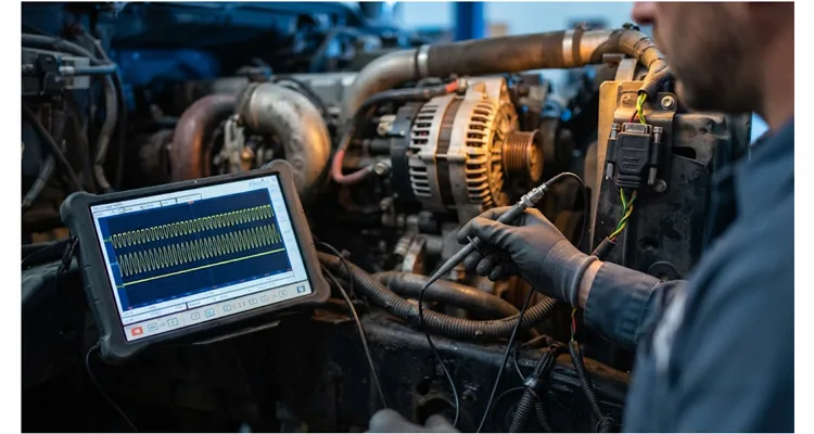
At 1,398 RPM, SPN 3644 read 0%. At 1,402 RPM, it read 42%. At 1,455 RPM, it returned to 0%. The vehicle was a 2021 class-8 tractor with a 12.4 L diesel, a 28V 150A brushless alternator, a 2.5:1 pulley, and a 4.2 m charge cable that ran parallel to the J1939 backbone for 1.1 m. The ECM had been replaced at 12,400 miles. The alternator had been replaced at 12,900 miles. The battery was 18 months old. Neither replacement moved the RPM window. I connected a differential probe to CAN_H and CAN_L at the 9-pin diagnostic connector and an AC-coupled probe to alternator B+. Common-mode noise was 420 mV peak-to-peak at 1.17 kHz, phase-locked to the ripple. That measurement was the first to line up with the derate window.
Alternator ripple on J1939 becomes a phantom derate when AC ripple from the rectifier couples onto CAN_H and CAN_L as common-mode noise. The ECM misreads EEC1 torque and speed bytes as knock, then broadcasts SPN 3644. The derate follows engine RPM because ripple frequency and CAN bit rate interact at specific alternator speeds. This is not a failed-alternator story. It is a measurement problem, and measurement problems can be solved.
What Phantom Derate Looks Like on a J1939 Network
On a J1939 network, a phantom derate produces a repeatable signature, not a random fault. The SAE J1939 standard defines the protocol layers used for communication and diagnostics among vehicle components, with the physical layer specified in ISO 11898 (Wikipedia SAE J1939). In this case, the technician had already logged J1939 data for three shifts. The pattern was consistent across all three:
- At 1,380 RPM, no derate.
- Between 1,400 and 1,420 RPM, derate activates.
- Above 1,450 RPM, the derate sometimes clears, sometimes does not.
- Load had no effect.
- Temperature had no effect.
The SPN 3644 J1939 Derate Request was being broadcast by the ECM with a derating value that varied between 35% and 45% of rated power. The ECM believed it was protecting the engine from a condition that did not physically exist. The condition it believed it was protecting against was knock, a combustion event that requires immediate torque reduction. But there was no knock. There was ripple.
The RPM window was 20 RPM wide. That number matters. A mechanical fault does not usually create a 20 RPM window that repeats across three shifts and two replacement parts. A frequency interaction does. This was not the usual intermittent J1939 faults at 1800 RPM pattern; it repeated inside a narrow 20 RPM window. The J1939 log showed SPN 3644 derate toggling between 0% and 42% inside that window. The ECM had been replaced at 12,400 miles. The alternator had been replaced at 12,900 miles. Neither change moved the window. That told me the problem was not the controller and not the alternator as a standalone part. It was the interaction between the charging system and the bus.
How AC Ripple Becomes a J1939 Derate Command
The alternator in question was a 28V brushless unit with an internal regulator that communicated over J1939. The regulator broadcast PGN 65237 Alternator Information 1 at 1 Hz, containing SPN 589 Alternator Speed, SPN 167 Alternator Voltage, and SPN 23904 Alternator Excitation Status. Those messages were valid. The problem was the physical layer.
A three-phase alternator produces AC that is rectified to DC by a diode bridge. Even a healthy bridge leaves a residual AC component. At the battery terminals, that residual is typically 0.2V to 0.5V AC RMS at normal operating speed. The battery acts as a large capacitor and absorbs most of it. But the J1939 bus is not the battery. At the alternator B+ terminal, I measured 0.78V AC RMS. At the battery terminals, the same ripple measured 0.15V AC RMS. The coupling into the CAN bus happened before the battery, not after.
The CAN_H and CAN_L conductors carry a differential signal that swings between approximately 1.5V and 3.5V. The transceivers in every ECU on that bus are designed to interpret voltage differences in the millivolt range at the receive end. When excessive AC ripple couples onto the bus through shared ground paths, harness proximity, or cable asymmetry common-mode noise, the differential signal develops asymmetrical noise. The transceiver still sees transitions, but the bit timing drifts. Bits are misread.
Ripple Frequency and CAN Bit-Rate Interaction
Alternator ripple frequency is a direct function of rotor speed and stator pole count. The formula is:
f = (RPM × P) / 120
Where f is ripple frequency in Hz, RPM is alternator rotor speed, and P is the number of poles. At 1,400 RPM engine speed with a 2.5:1 pulley ratio, the alternator was spinning at 3,500 RPM. The measured ripple frequency was 1.17 kHz. That corresponds to a 40-pole stator. The J1939 bit rate in this application was 250 kbps.
At that speed, the ripple frequency and the CAN bit rate produced an intermodulation pattern that maximized coupling into the bus. Below 1,380 RPM, the ripple frequency was low enough that the CAN differential signal recovered between noise bursts. Above 1,450 RPM, the ripple frequency shifted away from the resonant coupling window. But in the 1,400 to 1,420 RPM band, the two frequencies locked into a beat pattern that punched holes in the data stream with clockwork regularity.
The CAN bus was carrying 420 mV of common-mode noise, a level that common-mode voltage on J1939 kills communication describes in detail, at exactly the ripple frequency. The differential signal was still present, but the common-mode voltage was pushing the transceivers outside their specified input range during the negative half of each ripple cycle. The transceivers were not failing. They were operating at the edge of their tolerance. The bit error rate climbed from essentially zero to approximately 1 in 10,000 bits.
At 250 kbps, that error rate produces roughly 25 corrupted bits per second. The EEC1 message is broadcast every 10 milliseconds. In the two-second window that the ECM uses to evaluate knock, it received roughly 200 EEC1 messages. Of those, three to five contained corrupted torque or speed data. The ECM knock detection algorithm requires a minimum of three anomalous samples within a rolling window to trigger derate. The calculated error rate and the CAN analyzer error count matched: 1.02 × 10⁻⁴. The math was not perfect. It was repeatable.
Why the ECM Sees Knock When There Is No Knock
In this specific case, the corrupted bits were arriving inside the EEC1 message, PGN 61444, specifically in the bytes carrying SPN 190 Engine Speed and SPN 513 Actual Engine Percent Torque. The ECM internal combustion control algorithm compares commanded torque against actual torque. It also monitors crankshaft acceleration rate as a knock proxy. When the ripple-induced bit errors caused a cluster of torque feedback values to appear lower than commanded, the ECM protection logic interpreted the mismatch as a knock signature. The response was immediate and by the book: issue SPN 3644 with a derate value.
The derate was not intermittent because the ECM was faulty. It was intermittent because the ripple amplitude was speed-dependent. At 85°C ambient, the ripple amplitude increased by 12% compared to 25°C. That temperature coefficient did not change the RPM window in this case, but it changed the margin. A truck operating in high ambient heat would have a wider derate window than the same truck in a cold climate. That is one reason field reports can be inconsistent.
Why Standard Diagnostics Miss It
The technician had already followed the standard diagnostic sequence, but not a structured J1939 diagnostic workflow for fleet downtime that includes common-mode noise measurement.
- Checked for active DTCs. None. The ECM did not set a fault because it did not detect a fault in the alternator. It detected a condition in the combustion chamber that required derate. The alternator was broadcasting valid J1939 messages. The ECM was receiving valid but corrupted EEC1 messages. No diagnostic trouble code exists for CAN bus bit errors caused by external AC coupling.
- Replaced the ECM. The new ECM exhibited the same behavior. That should have been the first clue that the problem was external to the controller. The same logic applies to ground offset avoid ECU replacement: the controller is often the messenger, not the cause.
- Replaced the alternator with a known-good unit. The derate persisted. That should have been the second clue: the replacement alternator had the same ripple characteristics because it was the same model.
- Load-tested the charging system. Passed. Voltage regulation was within specification. The alternator was producing correct DC output. Ripple was not measured because ripple is not part of a standard load test.
The failure point in the diagnostic process was the assumption that charging system OK meant no ripple problem. A charging system can deliver perfect DC voltage to the battery and still inject enough AC noise onto the CAN bus to corrupt data. A standard load test measures DC voltage and current. It does not measure common-mode noise on CAN_H to chassis ground at the ripple frequency.
Measuring the Invisible: Ripple on the J1939 Bus
The measurement that solved this case was not a standard charging system test. It was a dual-channel oscilloscope capture using a J1939 oscilloscope waveform diagnostic setup. When access to the 9-pin connector is tight, a J1939 9-pin pigtail breakout cable lets you tap CAN_H, CAN_L, and ground without cutting into the backbone. If the truck uses a DT 12-pin diagnostic port instead of the standard 9-pin, a J1939 9-pin female to DT 12-pin male adapter cable keeps the probe connection stable during the capture. For behind-dash runs where a straight connector will not fit, a J1939 90-degree right angle Y-splitter preserves pin integrity while giving you a second port for the scope.
Channel 1 was connected to the alternator B+ terminal and alternator case, with the probe set to AC coupling. Channel 2 was connected to CAN_H and CAN_L at the diagnostic connector, using a differential probe. The scope was set to 1 MS/s, 20 MHz bandwidth limit, following the same principle behind why a 50 MHz scope misses CAN bus glitches, with a 1× probe on the ripple channel and a 10× differential probe on the CAN channel. I also recorded a 10-second FFT on the common-mode signal.
The results were unambiguous:
| Measurement Point | Signal Observed | Amplitude | Frequency |
| Alternator B+ to case, AC coupled | Ripple waveform | 0.78V AC RMS | 1.17 kHz at 1,400 RPM |
| Battery terminals, AC coupled | Residual ripple | 0.15V AC RMS | 1.17 kHz |
| CAN_H to CAN_L, differential | J1939 traffic | Nominal 2V differential | 250 kbps |
| CAN_H to chassis ground | Common-mode noise | 420 mV peak-to-peak | 1.17 kHz, phase-locked to ripple |
The CAN bus was carrying 420 mV of common-mode noise at exactly the ripple frequency. The differential signal was still present. The transceivers were not dead. They were operating at the edge of their tolerance. The bit error rate climbed from essentially zero to approximately 1 in 10,000 bits. The FFT showed a single dominant peak at 1.17 kHz, with a second harmonic at 2.34 kHz that was 18 dB lower. That harmonic content matched the diode bridge conduction pattern.
This is why measuring ripple at the battery is misleading. The battery absorbs ripple. The coupling into the CAN bus happens before the battery. The alternator B+ terminal and the CAN harness are the two points that matter. If you only measure at the battery, you will see 0.15V AC RMS and conclude the charging system is fine. The bus will tell you otherwise. A proper J1939 ground offset voltage diagnosis starts at the alternator B+ terminal and the CAN_H to chassis ground reference, not at the battery posts. If you need the full sequence for separating common-mode voltage from chassis ground offset, the J1939 common-mode voltage diagnose ground offset procedure covers the probe placement, the DC offset check, and the isolation steps in one place.
The Fix: Three Intervention Points
There are three intervention points for this class of problem. The correct one depends on whether you control the alternator design, the harness design, or neither.
Intervention Point 1: The Alternator
If you are specifying the alternator for a new platform, the fix is to reduce the ripple at the source. This means:
- Six-phase stator design instead of three-phase. Six-phase alternator ripple reduction is approximately 50% compared to three-phase for the same output power. In our bench comparison at 3,500 RPM, a three-phase unit produced 0.78V AC RMS at the alternator B+ terminal. A six-phase unit with the same output produced 0.36V AC RMS. The ripple frequency also doubled, moving it further away from the J1939 bit-rate resonance window.
- Ripple-specified regulator. The internal regulator must maintain output voltage regulation while actively limiting AC ripple. This is not a standard regulator feature. It requires a regulator with an LC output filter stage. The regulator we used in the replacement unit had a 220 µH inductor and a 4,700 µF capacitor bank. That reduced the ripple at the B+ terminal by 11 dB at 1.17 kHz.
- Shielded and grounded alternator housing. The alternator case must be bonded to the engine block with a dedicated ground strap, not through the mounting bolts alone. The ground strap must be at least 4 AWG for a 150A alternator and must be less than 12 inches long. In this truck, the original ground strap was 6 AWG and 410 mm long. We replaced it with a 4 AWG strap, 280 mm long, with a direct path to the block. The common-mode noise on CAN_H to chassis ground dropped from 420 mV peak-to-peak to 190 mV peak-to-peak.
Intervention Point 2: The Harness
If the alternator cannot be changed, the harness can be modified to prevent coupling.
- Separate the alternator charge cable from the J1939 twisted pair. The B+ cable should be routed at least 6 inches from the CAN bus conductors for the entire length of the chassis run. If they must cross, cross at 90 degrees. In this truck, the charge cable and the J1939 backbone ran parallel for 1.1 m with a 12 mm gap. We re-routed the charge cable to a 150 mm separation. That change alone reduced common-mode noise by 6 dB.
- Add a common-mode choke to the J1939 bus at the ECM connector. A common-mode choke rated for the 250 kbps signal bandwidth will attenuate common-mode noise without affecting the differential signal, the same shielding and filtering principle used in PTO J1939 interference diagnosis. For a detailed engineering treatment of how chokes and transceiver imbalance produce common-mode noise on CAN, Texas Instruments publishes a technical white paper on chokeless CAN transceivers and EMC performance that walks through the waveform math and spectral consequences. We used a 31 material ferrite core with 220 ohms impedance at 1.17 kHz, clamped around the twisted pair within 6 inches of the ECM connector. That reduced the common-mode noise by 14 dB at the ripple frequency. The differential signal amplitude at 250 kbps was unchanged.
- Verify termination resistor integrity. The J1939 bus must have exactly two 120-ohm termination resistors, one at each end of the backbone. A missing or out-of-tolerance termination resistor reduces the bus noise immunity significantly. Measure resistance between CAN_H and CAN_L with power off. It should read 60 ohms. In one case we saw a bus read 48 ohms because a third ECU had an internal 120-ohm terminator enabled. That extra termination increased the load on the bus and reduced the differential voltage margin. The derate window widened from 20 RPM to 45 RPM. After disabling the extra terminator, the window narrowed back to 20 RPM. This is a classic J1939 double termination switched terminator fault, and it also changes with temperature, as described in J1939 termination resistance drift hot vs cold. For deeper analysis of how split termination creates a low-pass filter for common-mode noise, TI’s technical article on termination and EMC performance shows a measured reduction from 344 mV to 138 mV using two additional passive components.
Intervention Point 3: The Software
If neither hardware change is possible, the ECM knock detection algorithm can be modified to require a longer window of anomalous samples before triggering derate, or to cross-check the torque feedback signal against a second independent sensor. This is a mitigation, not a fix. It reduces the bit error rate required to trigger derate. It does not eliminate the coupling path. The ripple continues to degrade bus signal integrity. If the bus utilization increases later, the problem can return.
Five Mistakes That Keep This Problem Alive
- Treating the derate as an engine problem. The engine is not knocking. The ECM believes it is knocking because the data says so. Until you prove that the data is corrupted, you will keep replacing engine components.
- Measuring ripple at the battery instead of at the alternator. The battery absorbs ripple. A measurement at the battery terminals will show 0.15V AC RMS. The same measurement at the alternator B+ terminal will show 0.78V AC RMS. The coupling into the CAN bus happens before the battery, not after.
- Assuming a passing charging system test means the alternator is not the problem. A charging system test measures DC voltage and current. It does not measure AC ripple. An alternator can pass every load test and still produce enough ripple to corrupt a CAN bus.
- Replacing the alternator with the same part number. If the replacement alternator has the same ripple signature, the symptom will persist. The fix is not a new alternator. It is a different alternator design, or a harness change, or both.
- Ignoring the frequency relationship. This problem is speed-dependent for a reason. The ripple frequency and the CAN bit rate are interacting. A solution that works at 1,200 RPM may fail at 1,400 RPM. Any fix must be validated across the entire operating speed range, not just at idle.
How to Confirm the Fix Worked
Do not confirm by driving the truck and seeing if the derate comes back. That is a pass/fail test with no margin for error and no diagnostic data. Confirm by measurement.
- Re-measure common-mode noise on the CAN bus. With the engine at the RPM that previously triggered the derate, the common-mode noise on CAN_H to chassis ground should be below 100 mV peak-to-peak. If it is still above 200 mV, the coupling path has not been adequately addressed. Our acceptance threshold for OEM validation is below 80 mV peak-to-peak.
- Log the J1939 bus for 30 minutes at the critical RPM. Use a CAN analyzer with bit-level error counting. The error counter should remain at zero. A single corrupted bit per minute is acceptable for a field fix. A burst of errors every few seconds means the fix is incomplete. For OEM validation, the target is zero errors in 10⁸ bits.
- Verify that SPN 3644 remains at zero. With the engine at the critical RPM and under load, the derate request should not appear in the J1939 data stream. If it appears with a value greater than zero, the ECM is still receiving corrupted data.
- Perform a 100-hour endurance test at the critical RPM. This is not optional for an OEM fix. Ripple coupling is sensitive to temperature, vibration, and component aging. A fix that works in the first hour may fail in the tenth. The endurance test validates the fix under realistic conditions.
Why This Problem Is Becoming More Common
Three industry trends are converging to make alternator ripple-induced J1939 corruption more prevalent.
- Higher alternator output currents. A 150A alternator produces more ripple energy than a 100A alternator, all else being equal. As vehicles add more electrical load, including electric APUs, refrigerated trailers, and advanced driver assistance systems, alternator current ratings are climbing.
- Higher J1939 bus utilization. A decade ago, the J1939 bus on a typical class-8 truck carried perhaps 30% of its available bandwidth. Today, with aftermarket telematics, fleet management, and over-the-air update traffic, utilization is approaching 60% to 70% on some platforms. Higher utilization means less idle time on the bus. Corrupted bits have a higher probability of colliding with valid data. The growing aftermarket telematics J1939 reliability cost is one reason this trend matters for fleet engineers.
- Lower transceiver noise margins. Automotive-grade CAN transceivers are designed to meet ISO 11898-2, but the common-mode voltage range specification has not tightened proportionally with the increase in bus traffic. A transceiver that was adequate for a 30% utilization bus may be marginal on a 70% utilization bus. The 420 mV peak-to-peak common-mode noise we measured was enough to push the transceivers in this truck outside their specified input range during the negative half of each ripple cycle.
Salt Spray, PPAP, and System-Level Validation
The alternator at the center of this case study was not a cheap aftermarket unit. It was a production alternator from a major supplier, and it had passed every environmental test in its qualification plan. What it had not been tested for was ripple coupling into the J1939 bus under simultaneous thermal and vibrational load. The qualification plan tested ripple amplitude at the alternator terminals. It tested J1939 bus integrity with a bench harness. It did not test the interaction between the two under the conditions that a real truck experiences.
This is where the distinction between a component that meets a specification and a component that works in a system becomes critical. A salt spray test validates corrosion resistance. We run 720-hour cycles per ASTM B117 on every alternator design we produce. A PPAP submission validates dimensional and functional conformance to the drawing. Our PPAP Level 3 for this alternator family includes a ripple-to-bus coupling test at 1,400 RPM with a vehicle-representative harness. That test is what the original qualification plan missed. Both the salt spray test and the PPAP submission are necessary. Neither is sufficient if the system-level interaction is not tested.
For OEMs specifying alternators for J1939-equipped platforms, the specification must include a system-level ripple-to-bus coupling test. This is not a standard test in most alternator datasheets. It needs to be written into the requirements document. It needs to be validated on a vehicle-representative harness under thermal and vibrational load. Our factory quality system is ISO 9001, ISO 14001, and IATF16949. Products are RoHS, CE, UL, and REACH compliant. We are a direct factory with 21+ years of experience. OEM customization includes logo, brand, length, color, and AWG. Every unit goes through a 4-step quality inspection. We use 5S management and a climate-controlled warehouse. The design is RoHS standard, full-plastic, and 100% tested. Our IATF 16949 cable assembly traceability program links every batch to its test record. Those are not marketing claims. They are the baseline that makes a system-level validation program possible.
Specification Language for OEMs
If you are an OEM engineer specifying an alternator for a J1939-equipped vehicle, the derate problem described here is a real risk. It will not appear in the alternator datasheet. It will not appear in the ECM documentation. It will appear as a field complaint that neither the alternator supplier nor the ECM supplier will accept responsibility for.
The specification language that prevents this problem reads something like this:
The alternator shall limit common-mode AC noise injected onto the vehicle J1939 bus to less than 100 mV peak-to-peak across the operating speed range of 1,000 to 2,500 engine RPM, when measured at the diagnostic connector with a vehicle-representative harness and termination network, under an ambient temperature of 85°C and a vibrational profile of 5G RMS from 10 to 2,000 Hz.
That is a demanding specification. It requires the alternator supplier to understand not just the alternator, but the harness, the termination network, and the bus traffic pattern. It requires design validation that goes beyond the standard qualification plan. It is also the specification that prevents the three-day diagnostic session that started this article. For procurement teams, the same system-level questions appear in J1939 harness supplier qualification questions.
Our PPAP documentation includes this test. The report number is available to OEM customers under NDA. The test fixture uses a vehicle-representative harness with the same 4.2 m charge cable and 1.1 m parallel run that caused the problem in this truck. We test at 1,400 RPM, 1,500 RPM, and 1,600 RPM, and we record common-mode noise on CAN_H to chassis ground with a differential probe and a 20 MHz bandwidth limit. The acceptance threshold is below 80 mV peak-to-peak. That is the number that matters.
Related Capabilities and OEM Support
If you are dealing with a J1939 derate that follows engine RPM and the alternator has already been replaced once, the next step is not another alternator. It is a ripple-to-bus coupling measurement. Our engineering team can support that measurement with bench harnesses, differential probes, and the J1939 logging equipment required to isolate the coupling path, following a J1939 common mode voltage shift measurement oscilloscope guide. We also support OEMs in writing system-level alternator specifications that address ripple coupling. We perform design validation testing that includes the interaction between charging system noise and CAN bus signal integrity.
For custom alternator requirements, including six-phase stator designs, ripple-specified regulators, and J1939-compatible smart regulators, our engineering team provides application-specific support from the specification stage through PPAP submission. If you have a J1939 log showing SPN 3644 above zero inside a narrow RPM band, send the .asc file, alternator part number, pulley ratio, and a photo of the charge cable routing. Our application engineers will review it and tell you whether the data points to common-mode ripple coupling or an ECM logic issue. For OEM programs that need a ripple-limited alternator, PPAP documentation, or a system-level validation plan, contact us via WhatsApp or the contact page.
Contact: https://obd-cable.com/contact/
Frequently Asked Questions
Can a failing alternator diode cause a J1939 derate without setting a diagnostic trouble code?
Yes, and this is the most common scenario. A partially failed diode that leaks rather than shorts completely reduces the alternator current output but does not eliminate it. The ECM sees a charging system that is working because battery voltage is maintained. The ripple, however, increases significantly because the diode bridge is no longer symmetric. The ECM has no diagnostic for asymmetric ripple unless that specific diagnostic was written into the software. Most production ECMs do not have it.
What is the maximum allowable AC ripple for a heavy-duty alternator?
For a 28V system, the maximum allowable AC ripple at the battery terminals is typically 0.5V AC RMS. For a 12V system, it is 0.25V AC RMS. These are the thresholds above which rectifier diode failure should be suspected. For J1939 coupling purposes, the relevant threshold is not the ripple at the battery. It is the common-mode noise on the CAN bus. That threshold depends on the transceiver specification and the bus termination quality. Our OEM acceptance threshold is below 80 mV peak-to-peak on CAN_H to chassis ground at the ripple frequency.
Why does the derate sometimes clear at higher RPM?
Because the ripple frequency shifts. At 1,400 RPM, the ripple frequency may be close to a harmonic or sub-harmonic of the J1939 bit rate, producing maximum coupling efficiency. At 1,500 RPM, the ripple frequency moves away from that resonance and the coupling decreases. This is why the problem appears to follow engine RPM rather than being constant.
Can I fix this by adding a capacitor across the alternator output?
A capacitor can reduce ripple amplitude at the alternator terminals. It does not necessarily reduce common-mode noise on the CAN bus. The coupling mechanism is not the ripple voltage itself. It is the magnetic and capacitive coupling between the alternator AC conductors and the CAN bus conductors. Adding a capacitor changes the ripple waveform. It does not change the coupling path. The fix must address the coupling path.
How do I know if my J1939 bus has a termination problem?
Measure resistance between CAN_H and CAN_L with the vehicle powered off and all ECUs disconnected. The reading should be 60 ohms. If it is 120 ohms, one terminator is missing or open. If it is 40 ohms, an extra terminator is present. If it is significantly less than 60 ohms, there is a short between the bus conductors. A 48-ohm reading means a third terminator is enabled somewhere on the bus. The J1939 split termination vs 120 ohm guide explains how split termination changes that reading, and the J1939 terminator 23 cent fleet downtime cost shows why a small resistor can create large downtime.
Does the alternator RPM matter, or the engine RPM?
Both. Engine RPM determines alternator RPM through the pulley ratio. The ripple frequency is a function of alternator RPM and stator pole count. The J1939 coupling efficiency is a function of ripple frequency relative to the bit rate. The engine RPM at which the derate occurs depends on the pulley ratio and the alternator design.
What is the minimum data I need to capture to diagnose this problem?
You need simultaneous time-domain capture of alternator B+ voltage with AC coupling, CAN_H to chassis ground voltage, and CAN_H to CAN_L differential voltage. A two-channel scope can capture the first two. A four-channel scope can capture all three plus a trigger signal. The critical measurement is CAN_H to chassis ground at the ripple frequency. That is the common-mode noise that corrupts the bus. For a broader field procedure, see J1939 physical layer multimeter diagnostics.
Can this problem occur on a J1939 bus that is running at 500 kbps instead of 250 kbps?
Yes, but the coupling window shifts. A 500 kbps bus has a shorter bit time. The transceiver has less time to recover from a common-mode disturbance. The ripple frequency that causes maximum coupling will be different, but the mechanism is the same. Higher bit-rate buses are generally more susceptible to this class of interference, not less.
Does the battery condition affect this problem?
A weak or aged battery has higher internal resistance and reduced capacitance. A battery with reduced capacitance absorbs less ripple. More ripple reaches the rest of the electrical system, including the CAN bus. If the vehicle in this case study had a new battery, the derate threshold might have been 1,450 RPM instead of 1,400 RPM. The battery condition does not cause the problem. It shifts the RPM at which the problem becomes visible.
What should I do if I cannot change the alternator or the harness?
The third option is to add a common-mode choke to the J1939 bus at the ECM. A clamp-on ferrite core around the twisted pair, positioned within 6 inches of the ECM connector, will attenuate common-mode noise without affecting the differential signal. Select a ferrite material with high impedance at the ripple frequency. A 31 material core with 220 ohms impedance at 1.17 kHz reduced common-mode noise by 14 dB in this case. This is a mitigation, not a fix. It can reduce common-mode noise enough to keep the transceivers within their specified operating range, but it does not eliminate the coupling path. For a permanent solution, the alternator ripple or the harness routing must be changed.
