

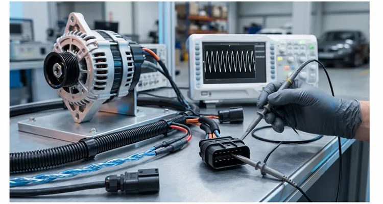
Short answer: An OEM alternator specification for J1939 ripple coupling should define a frequency-resolved ripple envelope, the battery impedance and harness length used for validation, a coupled ripple limit at the ECM supply pin, the J1939-11 harness assumptions, and regulator transient behavior during load steps and bus-commanded voltage changes.
When I audit an OEM alternator specification, the clause I test first is the one that ties ripple to a measurement node, a battery state, and a harness length. Most datasheets quote a ripple amplitude at rated RPM, but they omit the battery impedance, harness length, and measurement node behind that number. That omission is enough for a unit to pass the bench and fail at the ECM supply pin once it is installed in the machine.
What follows is the checklist I use on our factory floor when the alternator, charging harness, grounding system, and J1939 backbone have to be signed off as one coupled electrical system. More than twenty years of building charging and diagnostic harnesses has taught me that the specification has to force this conversation early. It is written for the engineer drafting the OEM alternator specification, not for a service manual reader.
Why a bench ripple number fails J1939 validation
A bench ripple number fails J1939 validation because it measures the source at the alternator terminal, not the coupled disturbance that reaches the ECM supply pin. Ripple is a byproduct of rectification: three-phase AC from the stator is flipped by the diode bridge into a lumpy DC waveform, and the varying component stacked on the DC level is ripple.
Technicians have used ripple amplitude as a diode-health proxy for decades. A failed diode produces a visible rise in AC content across the battery terminals. That logic still works for finding a dead diode. It does not predict whether an alternator will corrupt a 250 kbit/s differential bus.
J1939 does not fail because ripple exists. It fails when ripple energy lands in a frequency band and at an amplitude that couples through the charging and grounding path onto the CAN_H/CAN_L pair while a frame is being asserted. An alternator can look unremarkable on a handheld meter at idle and still inject enough common-mode disturbance at a specific engine speed to collapse the differential signal margin at the ECM. Field patterns like alternator ripple at 1,400 RPM and SPN 3644 show why a single idle check is not enough.
Diagnostic guides for some heavy-duty ECM families list SPN 168 FMI 8 as a dynamic supply-waveform instability fault, and field reports tend to cluster around ripple in the low-hundreds-of-hertz range with amplitudes in the hundreds of millivolts. Treat that as a troubleshooting clue, not a J1939 limit. The OEM alternator specification still has to define its own coupled ripple limit at the ECM pin and confirm it against the ECM supplier’s diagnostic guide. On some platforms using common heavy-duty ECM families, including certain Bosch EDC17-based systems, that fault association has been reported, but the exact trigger condition must be verified for the program.
The ECM is not measuring the alternator directly. It is measuring the consequence of the alternator’s output at its own power input pin, after that output has traveled through cables, connectors, grounds, and shared chassis impedance. An OEM alternator specification that stops at “ripple below a certain AC voltage” at the alternator B+ terminal is measuring the wrong node for a SAE J1939 system, and it is usually measuring under conditions that do not match the failure environment.
The coupling path the alternator specification must acknowledge
Ripple reaches J1939 through two distinct paths, and the specification must acknowledge both: conductive coupling through the shared supply and ground network, and near-field coupling through the charging harness. The alternator is the source. The harness and grounding system determine how much of that source reaches the data pair.
Conductive coupling of J1939 ripple through the shared supply and ground network
Every control module on the machine draws from the same battery bus and returns through chassis ground. When the alternator injects AC content onto B+, that content does not stay localized. It propagates through the supply wiring to each module’s power input, and it modulates the ground reference as return currents flow through finite chassis impedance.
A J1939 transceiver evaluates the difference between CAN_H and CAN_L. If a common-mode voltage disturbance appears equally on both lines, a well-designed differential receiver rejects it. The problem is that the disturbance is rarely perfectly common-mode. Harness asymmetry, connector pin impedance differences, and ground offset between modules convert a portion of the supply ripple into a differential error voltage superimposed on the bus signal. That is the mechanism behind J1939 common-mode noise from alternator ripple frequency and why common-mode voltage can kill J1939 communication even when the alternator looks acceptable on a meter.
SAE J1939-11 sets a two-volt maximum ground offset between any two ECUs on the bus, a number that exists because chassis return paths are never ideal. An alternator with excessive ripple spends part of that margin before the first frame is transmitted. Verify the J1939 revision used by your program before writing that limit into the OEM alternator specification.
Near-field coupling of J1939 ripple through the charging harness
The alternator-to-battery cable carries a high-current, ripple-rich waveform. If that cable is routed near the J1939 twisted pair, especially in tight engine-compartment packaging where harnesses share the same loom, the magnetic field around the charging conductor can induce a voltage in the data pair. Shield effectiveness and twist consistency determine how much of that induced voltage appears as differential noise.
That is why the OEM alternator specification has to name the harness, not just the alternator. A specification that defines source amplitude without defining the source’s frequency signature or the allowed coupling transfer is incomplete for J1939 applications. The specification should state the harness length, gauge, routing assumption, and shield termination used for any quoted ripple limit. In field work, this is also why intermittent J1939 faults at 1,800 RPM can appear only after the harness is installed in the machine.
What the alternator specification must actually include
The specification should include five elements:
- A frequency-resolved ripple envelope
- Defined test conditions that match the vehicle environment
- A coupled ripple limit at the ECM power input
- The harness electrical assumptions used for validation
- Regulator transient behavior during load steps and bus-commanded voltage changes
Each element closes a gap that a bench-only ripple number leaves open.
1. A frequency-resolved ripple envelope, not a single amplitude
The specification should define maximum permissible ripple amplitude as a function of frequency across the alternator’s operating speed range, from minimum idle to maximum governed RPM. A single peak-to-peak limit at one speed is not sufficient because the dominant ripple frequency shifts with rotor speed and rectifier phase count, and because coupling efficiency through the harness and grounding system is frequency-dependent.
At minimum, the frequency-resolved ripple envelope should cover 50 Hz to 2 kHz, with tighter limits in the 50–300 Hz band where supply-quality faults are most often reported. Above 2 kHz, the alternator’s output filter and the battery’s internal impedance provide increasing attenuation, but the specification should still state the limit rather than leave it undefined. The envelope should be written as a table or curve, not as a sentence with one number.
2. Defined test conditions for OEM alternator specification validation
A bench ripple measurement taken at 25°C with a resistive load bank and short leads tells the OEM very little about in-vehicle behavior. The specification should require ripple characterization under conditions that resemble the production machine, or at least state the conditions under which any quoted limit applies.
| Test variable | Bench default that hides problems | Condition the specification should require |
| Load type | Resistive load bank | Reactive load, actual vehicle battery, or electronic load emulation |
| Battery state | Fully charged, low impedance | 50–70% state of charge, aged battery with elevated internal resistance |
| Temperature | 25°C ambient | Cold start at minus twenty to minus thirty degrees Celsius and heat-soaked engine bay at eighty-five degrees Celsius or above |
| Harness length | Short bench leads | Production-length charging cable with production gauge and terminations |
| Ground return | Dedicated bench ground | Chassis return path with production bonding points and fastener torque |
The battery matters more than most specifications acknowledge. A healthy battery acts as a low-impedance shunt that filters a significant portion of alternator ripple before it reaches the rest of the electrical system. When the battery is aged, partially discharged, or has elevated internal resistance, that filtering effect diminishes.
In field records I have reviewed, 12V batteries with internal resistance above roughly eight milliohms correlate with repeated supply-quality faults even when the alternator passes a bench ripple test at room temperature. The specification should require ripple validation across a battery impedance range, not just with a new battery. It should also record the battery state of charge and internal resistance at the time of test.
3. A coupled ripple limit at the ECM power input, not only at the alternator B+ stud
The specification element most often missing is a coupled ripple limit at the ECM power input. The alternator supplier controls the source amplitude. The OEM controls the harness, grounding, and module placement. Neither party currently owns the coupled result at the ECM unless the OEM alternator specification assigns that responsibility.
The specification should include a system-level validation requirement: with the production alternator installed in the production harness and grounding configuration, the AC-coupled ripple measured at the ECM power input pin must remain below a defined limit across the engine operating envelope. A starting criterion I use is below 200 mV AC-coupled at 2000 RPM, measured at the ECU supply pins with the battery impedance and harness length recorded. That is not a universal law. It is a defensible starting point because it forces the alternator, harness, and grounding designs to be validated as a coupled system.
| Measurement node | What it tells you | What it misses |
| Alternator B+ and ground | Source amplitude under bench conditions | Coupled effect at the module and harness transformation |
| Battery terminals | System shunt effect at the installed battery | ECM-pin disturbance after harness and ground impedance |
| ECM supply pin | Coupled disturbance the module actually sees | Source origin unless paired with alternator and harness measurements |
The measurement node matters because ground offset and crimp resistance can consume the same margin the ripple limit is supposed to protect. That is why I cross-check the 10 mV rule for ECU ground offset specs and the 3.2 milliohm crimp resistance drift that shifts J1939 ground offset before signing off a coupled ripple record.
4. Harness electrical parameters for J1939 alternator validation
The OEM alternator specification should cross-reference the J1939 physical layer requirements so that alternator validation is performed against the same harness assumptions the OEM will use in production. For the data pair, SAE J1939-11 defines a shielded twisted pair with characteristic impedance of 108–132 ohms, conductor size of 0.5 square millimeters, 20 AWG, or 0.8 square millimeters, 18 AWG, and specific capacitance limits between conductors and conductor-to-shield. Verify the revision used by your program.
The charging circuit return path and the data pair shield termination must be defined as part of the same grounding strategy, not treated as separate electrical domains. If the alternator’s ripple performance is validated on a bench with a one-meter cable and then installed with a four-meter charging cable routed alongside the J1939 backbone, the validation is void.
The specification should require the alternator supplier to state the harness impedance and length assumed in any ripple characterization. The OEM should verify that the production harness falls within those assumptions before approving the alternator for the program.
5. Regulator transient behavior under J1939 communication interaction
Modern J1939-enabled regulators communicate charging system status over the bus and may adjust output based on battery condition messages. The specification must define acceptable regulator transient behavior when the bus is active and when load steps occur. A regulator that produces a clean steady-state waveform but oscillates during a load dump or a battery state-of-charge update can still corrupt bus traffic without violating a static ripple limit.
At minimum, the specification should require characterization of ripple during a 50% load step and during a communication-initiated charge voltage change. Apply the same frequency-resolved limit to the transient interval as to steady state, and capture the CAN_H/CAN_L differential signal at the same time so the reviewer can see whether the transceiver margin collapses during the event.
A representative case that shows why the coupled specification matters
A representative field pattern I use in training is a 24V wheel loader that passes an idle ripple check but resets the dash at 1,800 RPM. The machine runs normally at low idle. At exactly 1,800 RPM, the dashboard goes dark, the transmission drops into neutral, and the engine stumbles. Two seconds later, the dash relights and the machine runs until the operator hits high idle again.
The replaced modules were not the problem. A true-RMS meter set to AC volts across the battery terminals showed 0.1 volts AC at low idle and 4.5 volts AC at 1,800 RPM. A diode in the rectifier bridge had failed. At low speed, the ECU’s input capacitors absorbed the ripple. At high speed, alternator output increased, and the 4.5-volt AC component rode on top of the 24-volt DC level. The ECU saw a 28.5-volt peak, interpreted it as an overvoltage event, and shut down to protect its processors.
A rebuild that cost one hundred fifty dollars cured a problem that had already cost five thousand dollars in unnecessary module replacement. The dollar figure is not the lesson. The lesson is that an idle-only bench check would have passed the unit. A single amplitude limit at rated output might also have passed if the failed diode produced excessive ripple only in a narrow speed band.
What the specification needed was a ripple envelope across the speed range, measured under a load condition that reproduced the high-idle electrical state, with a limit tight enough to flag a 4.5-volt AC excursion before it became an ECU reboot. That is the difference between an alternator bench specification and a J1939-coupled alternator specification.
How to verify a candidate alternator against the coupled requirement
Run a five-step verification sequence before approving an alternator for a J1939 machine, regardless of what the supplier’s datasheet claims. The sequence should produce a coupled record at the ECM pin, not just a bench certificate at the alternator terminal.
- Step 1 — Establish the ECM supply ripple baseline with a known-good alternator. Install a known-good unit, run the engine through idle, mid-speed, and governed speed under no-load and loaded electrical conditions, and capture AC-coupled ripple at the ECM power input pin with an oscilloscope. Set the vertical scale to 20 mV per division after DC offset removal. A 1 V per division setting will hide the very disturbances you are looking for. Use a time base of 10 ms per division to expose low-frequency envelope patterns and a faster time base to inspect individual switching events.
- Step 2 — Repeat with the candidate alternator under identical conditions. The candidate must stay within the same envelope as the known-good unit. If the candidate’s ripple crosses 200 mV AC-coupled at any operating point where the baseline unit stayed below 100 mV, the candidate requires further investigation before approval.
- Step 3 — Introduce the production battery at end-of-life impedance. Replace the test battery with one at 70% state of charge or with a calibrated internal resistance above eight milliohms. Re-run the speed sweep. A candidate that passes on a healthy battery but exceeds the envelope on an aged battery is not qualified for field service.
- Step 4 — Run the load-step and communication-transient tests. Apply a 50% electrical load step and trigger a J1939-commanded charge voltage change while capturing both the ECM supply ripple and the CAN_H/CAN_L differential signal. Confirm that the differential signal eye opening remains within the transceiver’s specified thresholds throughout the transient.
- Step 5 — Document the coupled result, not just the source result. The approval record should contain the ECM-pin ripple envelope, the battery impedance at test, the harness length and gauge, and the grounding configuration. A bench certificate from the alternator supplier is a starting point, not an approval.
Supplier selection criteria that predict field behavior
Ask for audit evidence, not a certificate portfolio alone. The following table reflects what I verify during a supplier audit, with the distinction between a catalog supplier and a factory that understands the coupling problem.
| Verification item | What a catalog supplier typically provides | What a J1939-capable factory should provide | Audit evidence to request |
| Ripple characterization | Single amplitude at rated RPM on a resistive bench | Frequency-resolved envelope across speed and load, with test conditions documented | Coupled ripple test report with oscilloscope captures at the ECM pin |
| Harness assumptions | Not stated | Charging cable length, gauge, and routing assumptions defined for any quoted limit | Harness drawing and validation setup photo with length and gauge marked |
| Battery condition | “Good battery” unspecified | Ripple validated across a stated battery impedance range | Battery impedance record and state-of-charge log for each validation run |
| Regulator transient data | Steady-state regulation window only | Load-step and communication-transient ripple data at the ECM input | Transient test record showing CAN_H/CAN_L and ECM supply ripple on the same time base |
| PPAP / APQP | Certificate copy | Full PPAP with PFMEA linked to the ripple control plan and harness interface | PFMEA line item for diode quality, harness coupling, and regulator transient control; control-plan page for coupled ripple screening |
| Traceability | Lot code on label | Winding, diode batch, and regulator firmware traceable to the coupled test record | Traceability sheet linking serial number to diode batch, winding record, regulator firmware version, and coupled test record |
| Factory process control | ISO 9001 certificate | IATF 16949, ISO 9001, ISO 14001, 5S management, climate-controlled component storage, and four-step inspection including 100% end-of-line ripple screening; RoHS, CE, UL, and REACH declarations where applicable | IATF certificate and audit scope, 5S audit records, warehouse temperature log, four-step inspection records, 100% test log, RoHS and REACH declarations, CE and UL certificates |
A direct factory with more than twenty years of harness and charging-system experience will usually have the test infrastructure to run coupled validation, but it will not volunteer that capability unless the OEM asks for the right records. The OEM alternator specification is what forces the conversation onto the coupling path. The same discipline appears in J1939 harness supplier qualification questions and in the seven-question audit for a custom OBD cable supplier.
Our own floor runs ISO 9001, ISO 14001, and IATF 16949 certification, with 5S discipline and a climate-controlled component warehouse; the environmental management system is documented under ISO 14001. Assemblies are built to RoHS, with full-plastic design, 100% testing, and a four-step inspection sequence; CE, UL, and REACH declarations are supplied where the program requires them. For OEM customization programs, logo, brand, length, color, and AWG are configured after the coupled requirement is agreed. The useful audit conversation is not about the certificate wall. It is about the PFMEA line that names the diode batch, the control plan page that shows where coupled ripple is screened, and the test record that proves the ECM-pin limit was met with the production harness and an aged battery. That is also where PPAP Level 3 documentation for cable assemblies belongs in the review.
Technical intake for OEM engineering teams
If you are writing the coupled ripple clause now, send the harness length, battery impedance assumption, ECM supply-pin location, and speed sweep you plan to validate. Our OEM engineering team will review the test plan before a sample is built. Logo, brand, length, color, and AWG are configured after the coupled requirement is agreed, not before.
For the technical intake, use WhatsApp: https://api.whatsapp.com/send/?phone=8617307168662&text=Need+Help%3F+Chat+linda+WhatsAPP&type=phone_number&app_absent=0
Or use the contact page for a J1939 alternator specification review: https://obd-cable.com/contact/
The first step is agreeing on what the specification must prove at the ECM pin.
FAQ
Does SAE J1939 define a maximum alternator ripple voltage?
No. J1939 defines the physical layer, data link, and diagnostic messaging, but it does not set an alternator source ripple limit. Diagnostic thresholds reported for SPN 168 FMI 8 are platform-specific clues. The OEM alternator specification must define its own coupled ripple limit at the ECM power input and confirm it against the ECM supplier’s diagnostic guide.
Why does an alternator pass a bench ripple test and still cause J1939 faults in the field?
Because the bench test measures the source at the alternator terminal under short-lead, healthy-battery conditions. The field failure is a coupled event. The same source amplitude can produce different ECM-pin ripple depending on battery impedance, harness length and routing, and ground offset. A source that measures low on the bench can exceed the ECM tolerance after the charging and grounding path transforms it.
What is a reasonable coupled ripple target at the ECM for a 24V J1939 machine?
There is no universal number. A starting criterion should be derived from the ECM’s supply rejection specification and the transceiver’s common-mode range, then validated with the production harness, an aged battery, and a documented speed sweep. Record the battery impedance and measurement node with the result so the limit can be defended in a PPAP review.
Can a harness filter fix an alternator with excessive ripple?
A filter can attenuate high-frequency content, but it cannot correct a low-frequency envelope excursion caused by a failed diode or a regulator oscillation. If the ripple is in the low-hundreds-of-hertz band and exceeds the ECM’s tolerance, the correct action is to reject the alternator, not to add a filter that masks the symptom until a diode fails open.
Does battery condition change the coupled ripple result enough to matter?
Yes. The battery is the lowest-impedance element in the charging system and the primary shunt for alternator ripple. When internal resistance rises, the filtering effect degrades and ECM-pin ripple rises even if the alternator is unchanged. The specification should require validation across a battery impedance range and record the state of charge at each test point.
What wire gauge does J1939 require for the data pair, and does it interact with alternator ripple?
SAE J1939-11 specifies 20 AWG, 0.5 square millimeters, or 18 AWG, 0.8 square millimeters, for the data pair, with characteristic impedance of 108–132 ohms and shielded twisted pair construction. The gauge does not directly set ripple coupling, but shield termination and twist consistency determine how much alternator-induced common-mode disturbance becomes differential noise. Verify the J1939 revision used by your program.
How many alternator samples are needed to validate the coupled specification?
A practical floor is three production-representative units across the battery impedance range, with at least one unit run to thermal soak. If the supplier cannot provide three units with traceable diode and regulator batches, the coupled validation record is not strong enough for an OEM approval. The samples should be built with the production diode batch and regulator firmware.
Does an IATF 16949 certificate guarantee that the alternator supplier controls ripple coupling?
No. IATF 16949 certifies that a quality management system exists and is audited. It does not certify that the supplier’s ripple test stand measures at the ECM input, that the PFMEA addresses harness coupling, or that the control plan includes a coupled ripple screen. Ask for the PFMEA line item, control-plan page, and coupled test record directly.
Can an OEM specify a coupled ripple requirement without owning the harness design?
Yes, but the specification must then define the harness assumptions under which the coupled limit applies. If the OEM sources the harness separately, the OEM alternator specification should require the supplier to state the harness length, gauge, and shield termination assumed in its validation. The OEM should confirm that the production harness matches those assumptions before approving the alternator.
What is the first document to request from a new alternator supplier for a J1939 program?
Request the PFMEA and control plan section that addresses rectifier diode quality, harness coupling, and end-of-line ripple screening, not the ISO certificate first. A supplier that can show how a failed diode is detected at the coupled node before shipment is more valuable than one that can produce a certificate portfolio but cannot explain its ripple test setup.
