

Last updated: May 2026 | Reading time: 14 minutes
I got the call on a Tuesday. A logging fleet in Oregon had three Peterbilts that would randomly lose communication with their Allison transmissions. The symptom was always the same: the transmission would hang in whatever gear it was in, the dashboard would throw a J1939 Data Link Error, and then — just as mysteriously — everything would return to normal. The trucks had been to two different dealerships. One had its TECU replaced. Another got a new engine ECM. The third was on its second wiring harness inspection.
Nobody had asked the right question: What changed three weeks before the first fault appeared?
The answer was a fleet-wide aftermarket telematics rollout. Every truck had received an identical aftermarket GPS tracking unit, installed by a third-party shop over a single weekend. The devices were marketed as “plug-and-play J1939 compatible.” They were, in fact, injecting nearly 2 volts of common-mode noise onto the CAN bus and adding a third 120-ohm termination resistor that dragged the network impedance down to 41 ohms.
This wasn’t a software glitch or a defective ECU. It was a physical-layer problem hiding in plain sight — the exact kind of J1939 physical layer fault I’ve spent twenty-plus years chasing across fleet yards, construction sites, and agricultural operations on four continents. A single telematics installation error can burn through more money than the hardware itself ever cost, and I broke that math down in detail when I calculated what aftermarket telematics actually cost your J1939 network reliability.
This article is about what actually happens — electrically, at the bit level — when an aftermarket telematics unit connects to a J1939 network that was never designed to host it. Not the marketing promises. Not the protocol theory. The reality measured with a multimeter and an oscilloscope at 6 a.m. in a cold fleet bay.
The Peterbilt That Wouldn’t Shift
Let me give you the full picture on that Oregon fleet, because the details matter.
The trucks were 2022 Peterbilt 579s with Cummins X15 engines and Allison 6-speed automatics. The telematics units were mid-range GPS trackers sourced from a reputable supplier, each installed using a Y-splitter cable connected at the 9-pin diagnostic port under the dash. The installation shop followed the instructions exactly. The LED indicators lit up green. According to the telematics portal, data was flowing to the cloud within minutes of power-up.
What the installer didn’t know is that the Y-splitter cable contained a 120-ohm termination resistor across CAN-H and CAN-L. The Peterbilt already had two: one at the engine ECM, one at the chassis node near the ABS controller. When I measured the J1939 bus resistance and saw 41 ohms, I knew immediately a third termination resistor had snuck in — three 120Ω resistors in parallel never sum to 60. That drop meant every CAN transceiver was driving into a load it wasn’t sized for. The network doesn’t die; it just gets indecisive — and indecision at 250 kbit/s looks a lot like a ghost fault. I’ve captured this exact failure signature on scopes across dozens of fleet bays, and the J1939 termination mistakes behind it routinely cost fleets three thousand dollars or more in unnecessary ECU replacements.
Meanwhile, the telematics unit’s internal DC-DC converter — a cheap switch-mode supply — was coupling switching noise onto the CAN bus through a poorly isolated ground reference. At idle, this was a subtle 200mV ripple. Under load, when the converter drew harder, the noise amplitude reached nearly 2 volts peak-to-peak. That’s well within the territory where a CAN transceiver starts seeing phantom dominant bits.
The combination was devastating in ways that are invisible to standard diagnostic routines. Error frames would pile up in the controller registers during high-noise events, the TECU would lose synchronization with the engine speed message, and the shift schedule would freeze — but only under specific combinations of engine RPM, alternator load, and road vibration. Every time a dealership scan tool connected, the error counters had already reset after the key cycle. No permanent codes. No MIL. Just a truck that misbehaved unpredictably and a stack of repair invoices with no resolution.
We found it with two tools: a Fluke multimeter and a PicoScope. The bus resistance measurement took thirty seconds. Capturing the common-mode noise signature took another ten minutes. The repair — removing the Y-splitter’s built-in terminator and installing a proper isolated ground reference — took under an hour and cost less than fifteen dollars in parts.
Total cost of the misdiagnosis across three trucks before we arrived: approximately twelve thousand dollars in parts and labor. All of it avoidable.
The Electrical Rules That Break Silently
Before we talk fixes, I’m going to walk through the bus physics the same way I wish someone had walked me through it twenty years ago — not as a textbook, but as the handful of rules that, when broken, explain 90% of the aftermarket integration failures I see. If you’ve been around J1939 for a while, some of this you’ll recognize, but I’ve learned to look at these fundamentals with the suspicion of someone who has seen them fail in creative ways on real heavy-duty CAN networks.
Termination: The 60-Ohm Rule That’s Really a Warning
I don’t even glance at a wiring diagram until I’ve seen 60 ohms on the meter, measured across CAN-H and CAN-L with everything off. That single number defines the backbone: put a 120-ohm resistor at each physical end, and nowhere else. The moment a third 120Ω resistor shows up — tucked inside a Y-cable, for instance — the bus drops to roughly 40Ω. Transceivers engineered for 60Ω can’t develop clean signal swings into a 40Ω load, so the edges round off. The network doesn’t die; it just gets indecisive — and indecision at 250 kbit/s is exactly what I call a CAN bus ghost fault. I’ve watched a perfectly good network pass every static resistance check yet still derate under load; I broke down exactly why your multimeter can say 60 ohms while your fleet still derates in a deep dive on backbone design.
In my own investigation history, I encounter termination mistakes in a predictable order, and I’ve developed a few mental shorthands:
- The Hidden Third Wheel (frequency: ~1 in 3 aftermarket installs). A Y-cable or inline adapter with its own 120Ω resistor. Symptom: bus sits at 40Ω with power off. That was the exact fault on the Oregon Peterbilt. The fix: remove the extra terminator. I’ve pulled enough of these out of fleet trucks to fill a parts bin; the financial damage pattern repeats so consistently that I documented the full cost analysis of termination and stub length mistakes creating phantom faults.
- The Missing Bookend (frequency: common on DL1-style Volvo installs). Installer pulls a factory terminator, inserts a pass-through harness, and forgets to re-terminate at the far end. Symptom: 120Ω at the connector, reflections landing right in the sampling window. At 250 kbit/s and a 40-meter bus length, the reflection arrives about 400 ns later — dead-center in the next bit’s sampling point. That 42-nanosecond-level timing skew is exactly how J1939 bit sampling errors trigger bus-off events without leaving a single DTC behind.
- The Stub That Shouldn’t Exist (frequency: about 20% of construction equipment installs). Tapping into the bus mid-span rather than at an endpoint, creating a long, unterminated branch. The SAE J1939-11 spec limits stubs to 1 meter at 250 kbit/s. Many installers violate it by simply being connected to the wrong connector — one that’s a stub, not an end of the backbone. If you want to see the full financial impact of getting this wrong, I’ve laid out exactly how poor stub length decisions add fifteen thousand dollars per year to your maintenance budget.
- The ‘I Trusted the Drawing’ Error (frequency: highest in the first week of a fleet rollout). Nobody picks up a meter before or after the install. Documentation says the port is an endpoint; field reality says otherwise. I can count on one hand the number of shops I’ve visited that routinely check bus resistance before connecting aftermarket hardware. For a step-by-step walkthrough of the backbone layout that prevents this, our J1939 backbone design and stub length guide covers what the spec sheets don’t.
What “Noise” Actually Looks Like on a Scope
“Noise” gets thrown around loosely, so let me be precise — exactly the way I’d explain it to a technician standing next to me in a cold fleet bay, with a scope probing the CAN bus.
A CAN transceiver decides whether the bus is dominant or recessive by looking at the voltage difference between the two wires. When that difference hits about 0.9 volts, it sees a dominant bit — a logic zero. Below 0.5 volts, it’s recessive. The waveforms I see on the bench fall into three CAN noise categories:
Common-mode noise: both CAN-H and CAN-L ride up and down in lockstep relative to chassis ground. On a differential probe, you might not see it. But the transceiver inside the ECU sees its input pins inching toward the supply rails, and at some point the whole subtraction circuit saturates. On the Oregon trucks, the telematics unit’s switching power supply was coupling noise through its transformer onto the ground reference. The device was grounded to a dashboard bracket; the engine ECM to the cylinder block. Under load, that ground offset hit nearly 3 volts, pushing the common-mode voltage dangerously close to the transceiver limits. This exact mechanism — a ground offset that multimeters miss entirely — is what I call the silent network killer, and I’ve written a full diagnostic walkthrough on how to diagnose J1939 ground offset issues because it condemns more healthy ECUs than any other single fault.
Differential-mode noise: the difference between H and L develops wiggles that look like real CAN bus data. I’ve watched this on a PicoScope look exactly like a phantom start-of-frame bit — tiny pulses between H and L that a receiver can latch as legitimate traffic. On the Peterbilt, a subtle ripple grew to 200 mV of high-frequency hash under load, enough to fool a transceiver into thinking a message was arriving. Catching these subtle waveform anomalies before they trigger a parts-cannon response is the whole premise behind my guide to J1939 oscilloscope waveform analysis covering edge rates, ringing, and differential voltage.
Conducted noise from the power supply: A telematics unit pulling 2A transmitter pulses puts that same pulse shape onto the 12V rail. Any CAN transceiver fed from that rail without adequate filtering sees the pulse as common-mode wobble. A GSM modem drawing 2 amps in 577-microsecond bursts creates a supply ripple most CAN transceivers were never designed to reject. I’ve traced this back to cheap aftermarket GPS trackers more times than I can count. This one is invisible to the bus waveform unless you also probe the supply pins at the ECU.
Where the Noise Lives: A Look Inside the Telematics Box
I’ve cracked open enough dead telematics units to know exactly what’s inside. Most contain a CAN transceiver chip (common parts: NXP TJA1040, TI SN65HVD230, Microchip MCP2551), a cellular module from Quectel, Telit, or u-blox, a GNSS receiver, and a switch-mode power supply that steps 12V/24V down to 3.3V and 5V.
The difference between a clean unit and a problem-child lies in galvanic isolation. Well-designed units galvanically isolate the CAN side from the rest of the board — using an isolated DC-DC converter and digital isolators, or an integrated isolated CAN transceiver like the ISO1042. That breaks ground loops and blocks conducted noise from the modem. Less expensive units? The isolation barrier is either missing or implemented with a single capacitor that couples noise straight onto the CAN bus. The PCB layout often runs CAN traces next to switching converter traces, adding parasitic coupling.
None of this shows up on a spec sheet. The box says “J1939 compatible.” It doesn’t say “ground offset tested to 3V” or “common-mode rejection verified per SAE J1939-11 Section 5.3.” Fleet managers buy the promise — and then call me when the trucks start acting possessed. This is why I’m blunt with fleet directors about the real numbers: J1939 ground offset alone is costing the average fleet roughly seven thousand dollars per year in perfectly functional ECUs that got condemned and replaced because nobody measured the ground reference under load.
A Field-Proven Diagnostic Sequence
When a truck rolls in with unexplained J1939 faults and a telematics unit is installed, I follow a sequence that has never let me down. The tools are simple. The discipline of doing the steps in order is what produces answers. This method didn’t come from a training course — it came from tracing thousands of faults back to their physical-layer root cause, and I’ve seen it cut fleet downtime by seventy percent when applied systematically.
Step 1: Measure Bus Resistance (Key Off, Battery Disconnected)
When I step into a fleet bay, the first tool I grab is a Fluke multimeter — not a scan tool. I’m after J1939 bus resistance. Disconnect the battery, set the meter to ohms, and measure between CAN-H and CAN-L at any accessible point. The 9-pin diagnostic connector is fine if you’ve verified the pin assignment (standard Deutsch: Pin C = CAN-H, Pin D = CAN-L).
Here’s the field translation I use, learned from two decades of chasing J1939 termination faults:
| Resistance Reading | What It Means | Action |
| 58–62 Ω | Backbone is intact, no hidden terminator | Proceed to next step |
| ~120 Ω | One end is unterminated | Check the most distant ECU and any pass-through harness |
| ~40 Ω | Extra terminator present (adapter, Y-cable, or device) | Find and remove the third 120Ω resistor |
| >1 kΩ | Both terminators gone or wire open | Inspect for open circuit, especially if truck ran recently |
| <35 Ω (battery disconnected) | Bus is loaded hard (moisture, partial short) | Inspect connectors for contamination; check transceivers |
If the reading isn’t about 60 ohms, stop. Do not chase ghosts with a scan tool until this number is right. I’ve wasted too many hours ignoring that rule. For a complete diagnostic checklist that steps through this entire sequence in under 20 minutes — from resistance checks to waveform capture — our J1939 physical layer troubleshooting guide walks through every measurement.
Step 2: Identify All Terminators Physically
Locate every 120-ohm termination resistor in the system. On Class 8 trucks, one’s near the engine ECM (usually a sealed Deutsch cap), the other near the cab fuse block or ABS controller. On ag and construction iron, I’ve found them inside frame rails, behind cab headliners, once inside a hydraulic reservoir compartment. Account for any resistor built into adapter cables, Y-splitters, or the telematics hardware itself.
Step 3: Measure Common-Mode Voltage (Engine Running, All Loads Active)
Meter from CAN-H to engine block ground, then CAN-L to the same reference. With the engine running and everything switched on — headlights, HVAC fan, alternator under load — these voltages should hover around 2.5V and stay within a few hundred millivolts of each other. If either measurement exceeds 3.5V or drops below 1.5V relative to ground, the common-mode voltage is approaching transceiver limits. On the Oregon Peterbilt, exactly this measurement pointed me toward the ground offset that was killing CAN communication.
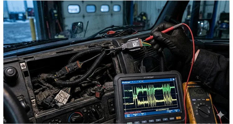
Step 4: Scope the Differential Signal
A multimeter can’t show you what’s actually happening to the waveform. You need an oscilloscope with at least 20 MHz bandwidth. Connect Channel 1 to CAN-H (ref ground), Channel 2 to CAN-L (ref ground), and display the math trace Ch1 − Ch2. Trigger on a falling edge around 1.5V.
When I put the Pico on that Peterbilt, here’s what stood out — and what I now look for on every J1939 integration check:
- Transitions: Sharp as a knife edge. Any rounding, even a slight shoulder, tells me the bus sees too much capacitance — often a long stub or a telematics unit with a lazy CAN receiver design.
- Overshoot: We saw nearly 400 mV of ringing after each edge. Textbook impedance mismatch, and the culprit was those hidden 40 ohms. If you see >200 mV, don’t adjust probe compensation; adjust your termination.
- Recessive noise: The baseline between dominant bits should be a flat line near zero differential. On the Peterbilt, it had a 5-mV ripple from the DC-DC converter. That ripple grew to 200 mV under load — enough to generate phantom edges. I now treat any visible fuzz in the recessive zone as suspect until I trace it to a source.
- Dominant voltage: Should sit steady at 2.0–3.0V differential. If it’s below 1.5V, the bus is overloaded — too many nodes, wrong termination, or a weak CAN transceiver.
The scope rarely lies, but a multimeter will tell you a bus is healthy right up until modules start dropping offline. I’ve documented how a two-hundred-dollar USB oscilloscope can prevent twelve thousand dollars in misdiagnosed ECU replacements — real cases where the waveform revealed what the meter missed.
Step 5: Isolate the Telematics Unit and Compare
Disconnect the aftermarket telematics device. Repeat the resistance and scope measurements. If the bus resistance changes when the device is connected, the device or its cabling is introducing a termination error. If the noise signature changes — particularly if high-frequency ripple disappears — the device is the source of CAN bus noise. This comparison is the single most definitive step, yet I’ve seen ECUs replaced wholesale before anyone thought to do it.
Step 6: Check the Ground Path
Measure resistance between the telematics ground point and the engine block. Above 1 ohm suggests trouble. Then measure voltage between these two points under load; anything above 100 mV indicates a ground offset that can collapse common-mode rejection and inject physical-layer errors. I’ve also learned to run a simple voltage drop check across the power feed before chasing CAN signals — our factory’s return analysis over three years showed that over sixty percent of “intermittent J1939 communication failure” returns traced back to power feed corrosion, not transceiver failures.
The ideal ground for a telematics device on J1939 is the same reference the vehicle’s primary ECUs use — engine block or dedicated sensor ground bus. Chassis ground is not interchangeable with that, and treating it as such is one of the most persistent installation mistakes I see in fleet aftermarket telematics integration.
The Five Mistakes I Keep Finding
These recur regardless of vehicle make, telematics brand, or installation shop. I’ve ordered them by how often I run into them in the field — and how much damage they cause to a J1939 network.
1.The Hidden Third Wheel — Over-Termination Through Y-Splitters
I find an extra 120Ω resistor on roughly one in three aftermarket installations I inspect. It’s almost always in a Y-cable or inline adapter — a J1939 termination error that drags bus impedance to 40Ω. The fix: check every cable in the signal path. If you find a third terminator, remove it. If the telematics unit itself has internal termination (some are switchable by jumper), disable it.
2.Connecting at the Wrong Point in the Topology
Splicing into the twisted pair mid-backbone — rather than at a designated connector — creates a stub that may exceed the 1-meter limit and generates reflections from the splice point. Use the OEM-provided aftermarket connectors whenever possible. Volvo’s RP1226 and the standard green 9-pin diagnostic port are designed for CAN bus access. If the vehicle lacks a dedicated tap point, connect at one of the two backbone endpoints using a pass-through connector that preserves the terminator. Never mid-span.
3.Ignoring the Ground Reference
I’ve measured a 3-volt ground offset between a telematics unit grounded to a dashboard bracket and an engine ECM bolted to the cylinder block. At that offset, some transceivers stop receiving entirely, causing intermittent J1939 communication faults. The voltage shifts with alternator load, battery state, temperature, and which accessories are running — that’s why these failures feel random. Ground the device to the same reference as the vehicle ECUs, or use a device with galvanic isolation rated for at least 500V for heavy-duty trucks.
4.Assuming “Listen-Only” Means Electrically Invisible
Even in silent mode, a telematics device adds capacitive load, can introduce ground offsets, and (depending on transceiver configuration) may still assert error frames or acknowledgment bits. I’ve personally scoped dozens of “listen-only” J1939 telematics units and caught them red-handed injecting error frames — a failure mode I dissected in detail when I investigated how J1939 transceivers can fail partially and still corrupt the bus while appearing functional to a scan tool. True electrical invisibility requires a high-impedance receiver input, galvanic isolation, and disciplined PCB layout. Per the broader CAN specification, a properly terminated CAN bus with high-impedance receivers ensures that even a device in listen-only mode does not inadvertently load the differential lines. Most aftermarket units meet none of these.
5.Relying on Scan Tools Instead of Physical-Layer Measurement
A scan tool reads fault codes and parameters. It cannot tell you that the differential voltage is collapsing to 1.2V instead of holding at 2.0, or that there’s a 5 MHz ripple riding on the recessive state, or that the bus resistance is 41 ohms. I’ve watched shops spend days on ghost faults measurable in thirty seconds with a multimeter and a PicoScope. The obsession with software diagnostics at the expense of electrical fundamentals is, in my experience, the biggest source of wasted diagnostic labor in fleet maintenance. A systematic 30-minute physical layer check — resistance, voltage, ground — can save a fleet eight hundred dollars or more in dealer diagnostic fees on a single truck.
I put hard numbers behind this exact claim in a dedicated fleet case study. Our J1939 downtime ROI calculator walks through a 50-truck fleet model where a three-step physical layer protocol — the same one I just described — cut diagnostic time from eight hours to thirty minutes per event and delivered a first-year ROI of 18,764 percent, saving the fleet over four hundred twenty-nine thousand seven hundred dollars annually.
Verifying the Fix: My Checklist
After correcting termination and addressing noise sources, I verify systematically. This isn’t a manufacturer’s checklist; it’s one I’ve scratched onto a thousand notepads in fleet bays across four continents.
| Check | Specification | Why It Matters |
| Bus Resistance (key off, device connected) | 60Ω ± 10% | Confirms correct termination with new hardware |
| Common-Mode Voltage (all loads active, ref engine block) | 1.5V – 3.5V; both lines track | Prevents transceiver saturation and physical-layer errors |
| Differential Waveform | <200 mV overshoot; clean recessive baseline | Verifies signal integrity and impedance match on the CAN bus |
| Error Frame Count (engine start, idle, load, road test) | Zero | Ensures no phantom bits corrupt communication |
| Telematics Transmission | Zero dominant bits asserted | Confirms true listen-only behaviour on the J1939 network |
| Documentation | Save resistance, waveform, and error log | Warranty protection and trend reference |
I’ve seen this documentation save fleets tens of thousands in warranty disputes, especially when OEMs try to point fingers at the aftermarket telematics installation.
The Parts That Make This Work
After twenty years of manufacturing J1939 cables and connectors, I’ve learned the physical components matter more than most realize. A network doesn’t fail because the theory is wrong; it fails because a connector transition doesn’t hold 120Ω impedance, or a termination resistor drifts after a few hundred thermal cycles.
The 9-pin Deutsch connectors we manufacture maintain controlled impedance through the connector body with gold-plated contacts that resist fretting corrosion across tens of thousands of cycles. For telematics integration specifically, we build Y-splitters without built-in termination — because any competent installer should measure the J1939 bus and make that decision deliberately, not inherit a hidden resistor in a J1939 Y-cable. When space behind the dash is tight — which it almost always is on a modern truck — the physical geometry of the connector matters as much as the termination design. Our 90-degree right-angle J1939 Y-splitter cable built on Deutsch DT connectors addresses exactly this: it routes cleanly behind panels without bending pins or stressing the harness, while preserving the correct termination scheme that the Oregon Peterbilt’s original Y-cable destroyed.
We also produce inline pass-through adapters that accept the vehicle’s original terminator at one end and provide a clean tap point for the telematics unit at the other. No guesswork about whether a cable contains an extra terminator. Every J1939 adapter cable we ship supports clean aftermarket telematics installation.
Every assembly passes four inspection gates: continuity, pinout verification, hipot at 500V, and visual under 10x magnification. Our warehouse operates under 5S management with climate control, because connector contact resistance shifts measurably with humidity — a detail that matters when the cable is installed on a truck that runs from Saskatchewan winters to Texas summers.
Our factory holds ISO 9001, IATF 16949, ISO 14001; our products carry CE, RoHS, REACH, UL. These aren’t badges. They’re verification that the cable you install today won’t become the intermittent fault someone chases three years from now.
Questions Fleet Managers and Technicians Ask Me
Over the years, certain questions come up again and again. Here’s how I answer them, usually standing next to a truck with a meter in hand and a J1939 network to probe.
“Why does our bus read 40 ohms after we plugged in the telematics?”
A fleet manager called me with exactly this last winter. I said, “Because somewhere between the diagnostic port and your device, there’s a third 120-ohm resistor hiding — probably in the Y-splitter cable. Three 120s in parallel on a J1939 bus give you about 40 ohms, not 60. Find that extra one and pull it out — just like we did on that Peterbilt in Oregon.” He found it in the inline adapter the supplier had included. Problem solved in fifteen minutes.
“Can a device that only listens really cause problems?”
Yes, and I’ve had this argument with more than one telematics provider. Even in silent mode, a device adds capacitance that slows edge rates. If its ground reference differs from the ECUs, it introduces a common-mode offset that may saturate a receiver when the alternator kicks in. And I’ve personally scoped units in “listen-only” mode that still threw error frames onto the CAN bus. If you need true electrical invisibility on a J1939 network, you need galvanic isolation and a specifically high-impedance receiver input. The SAE J1939 standard, which defines the physical layer for commercial vehicles, assumes a disciplined backbone — and every extra device, even a passive one, alters the carefully designed impedance profile.
“How do I know if the telematics unit is injecting noise onto the CAN bus?”
I always answer this one the same way: put a differential probe on the J1939 CAN bus with the aftermarket telematics device connected and powered, then disconnect it. If high-frequency ripple disappears when the device is unplugged, it’s the culprit. On the Peterbilt, the ripple was in the 150 kHz to 2 MHz range — exactly the switching band of a cheap DC-DC converter inside the GPS tracker.
“Should I ground the telematics to the chassis or the engine block?
The telematics unit needs to see the same ground potential as the vehicle’s CAN transceivers. In a heavy-duty truck, that’s the engine block or a dedicated sensor ground bus, not the dashboard bracket. I’ve measured a 3-volt ground potential difference between a telematics unit screwed to the dash and an engine ECM bolted to the block. That offset pushed the common-mode voltage right to the rail, killing CAN communication under load. If you’re unsure, measure the voltage between your proposed ground and the engine block under full load. Anything above 100 mV is a ground offset waiting to cause intermittent J1939 faults.
“What’s the right way to connect at the 9-pin diagnostic port?”
First, verify with a meter that the port is actually at the backbone endpoint and not a stub. Many heavy-duty trucks route that green 9-pin connector as a stub, not a J1939 backbone end. Measure bus resistance before you connect anything. If a terminator is present at the port, your installation must preserve it in the correct position — use a pass-through adapter that re-terminates after the tap. Confirm 60 ohms when you’re done. This simple step prevents a whole class of termination errors.
“Does the J1939 standard even allow aftermarket devices?”
J1939-11 and J1939-15 don’t prohibit aftermarket hardware, but they also don’t explicitly make space for it. The standards assume all nodes are validated as part of the vehicle integration. That means the responsibility falls on you, the installer, to make sure your device doesn’t violate the electrical parameters the spec demands. I always advise fleets to treat any aftermarket telematics as an untested node and verify the physical layer before signing off.
“Why do these faults only show up sometimes?”
Marginal conditions — a bus sitting at 41 ohms, a common-mode voltage hovering near the rail — produce J1939 communication errors only when additional stresses align: cold-soak startup, full alternator load, a specific vibration frequency, or heavy bus traffic from a regen event. This is exactly why bench testing passes and the road test fails. The CAN physical layer is right at the edge of failure, and it doesn’t take much to push it over. I’ve documented exactly how these phantom J1939 bit sampling errors drain four thousand dollars per year from fleets that keep chasing them with software updates.
“What certifications should I look for in J1939 cables?”
As a baseline: UL listing, RoHS, REACH. For heavy-duty reliability, look for conformance to the J1939-11 or J1939-15 physical layer tests. On the connector side, insist on gold-plated contacts and IP67 or better environmental sealing. I’ve seen nickel-plated contacts on J1939 connectors corrode to the point of creating bus errors in less than a year on a coastal logging truck.
“Do I really need an oscilloscope, or is a multimeter enough?”
A meter catches termination and ground problems. It cannot see rounded edges, ringing, recessive noise, or the intermittent bit error that resets after a key cycle. An oscilloscope with at least 20 MHz bandwidth and math trace capability is the minimum for signal integrity on a CAN bus. You can buy a two-channel scope capable of this for under five hundred dollars. It pays for itself the first time it prevents an unnecessary ECM swap on a J1939 network.
“Can a telematics device damage the vehicle’s ECUs?”
Direct electrical damage is unlikely — CAN transceivers are tough. But a device that continuously generates bus errors can push ECUs into bus-off state repeatedly, log persistent fault codes, and in some implementations trigger fail-safe modes that reduce engine power or lock out gears. The damage is operational, not electrical, and it’s expensive in downtime and misdiagnosis. I’ve testified as an expert in cases where a single faulty aftermarket telematics unit caused a fleet-wide CAN communication failure.
Need Engineering Support for Your Integration?
If you’re specifying a telematics installation across a fleet, or developing aftermarket hardware that must coexist cleanly on J1939 networks, I encourage you to get the physical layer right before the first unit ships. We regularly work with telematics providers and fleet operators on custom J1939 cable assemblies — connector selection, pinout verification, termination strategy, and ground referencing — to catch these problems at the design stage.
We offer OEM customization on every cable we build: connector type, length, wire gauge, color coding, and branding. Whether you need a single evaluation sample or production volumes with full IATF 16949 traceability, we can support your project. Our J1939 Y-splitter cables and pass-through adapters are designed from the ground up to prevent the exact termination and noise issues I’ve described in this guide.
Have a specific integration scenario you’d like to discuss? Reach out through our contact page or message us directly on WhatsApp. I read every inquiry personally, and I’m happy to help you think through the physical-layer details that make the difference between a clean J1939 telematics integration and a fleet-wide headache.
📞 WhatsApp: +86 173 0716 8662
📧 Contact Page: https://obd-cable.com/contact/
About the author: I’ve spent twenty-plus years designing, manufacturing, and troubleshooting J1939 physical-layer components. I’ve chased CAN bus faults through fleet yards, mines, construction sites, and agricultural operations. Our factory in China operates under ISO 9001, IATF 16949, and ISO 14001 quality systems with 5S-managed, climate-controlled production and warehousing. Every J1939 cable assembly is 100% tested before it leaves the floor. I write about what I’ve learned the hard way so you don’t have to.
