

A 50-Fleet Case Study in Turning Resistance Measurements into Recovery Dollars
I was on the phone with a fleet director in Ohio three months ago. He manages fifty-two Class 8 trucks running regional LTL routes. His problem: six trucks in the previous quarter had gone down with what his techs were calling J1939 ghost faults. Engine derate. Transmission stuck in limp mode. ABS warning lamp lit with no wheel-end fault. The trucks would act up for an hour, then self-resolve. The dealer had one of them for three days and returned it with “no fault found” and an invoice for two thousand three hundred forty dollars in diagnostic labor.
“How much is this actually costing me?” he asked. Not the repair bill. The downtime.
That question is the reason this article exists. I’ve fielded it from fleet managers, maintenance directors, and owner-operators enough times to know that most people can’t answer it with a number — not a real one. They feel the pain but they can’t quantify it. And if you can’t quantify it, you can’t justify investing in the solution, even when the solution costs less than a decent torque wrench.
What follows is a method for calculating the real return on using basic diagnostic tools — a digital multimeter that reads true RMS, a know-your-network mental model, and a systematic test sequence — to cut J1939 downtime. I’ll walk through the numbers with a real-case framework. No software subscription required. No telematics platform to deploy. Just the tools most shops already own and the knowledge to use them with purpose.
Part 1: What a J1939 Downtime Event Actually Costs — the Math
Before we talk about ROI, we need a credible cost baseline. The American Transportation Research Institute (ATRI) pegged 2024 marginal operational costs at ninety dollars and eighty-nine cents per hour with fuel, and seventy-one dollars and fifty-seven cents without fuel. That’s the running cost, not the downtime cost. When a truck is parked, you stop burning fuel, but you don’t stop paying for the truck, the insurance, the driver, or the missed service window.
I build downtime cost from four components:
| Cost Component | Conservative Estimate (per hour) | Notes |
| Lost revenue / utilization value | One hundred twenty to three hundred dollars | Depends on freight type; refrigerated LTL runs higher |
| Idle driver wages + benefits | Thirty to forty dollars per hour | Driver is still on the clock during a roadside event |
| Customer penalty / goodwill erosion | Fifty to one hundred dollars per hour | Late penalties, lost future loads |
| Replacement vehicle / rental | Forty to sixty dollars per hour | If you have access to a spare; if not, the load dies |
Conservative blended downtime rate: two hundred fifty dollars per vehicle-hour. In heavy industrial or oilfield applications, I’ve seen that number climb past five hundred dollars per hour — lost production on a fracking spread doesn’t wait for a tow truck.
Let’s anchor this to a realistic fleet maintenance scenario:
- Fleet Profile: 50 trucks, average 4 unplanned J1939-related downtime events per truck per year, average event duration 8 hours (tow, diagnose, repair, return to service).
- Annual Downtime Hours: 50 × 4 × 8 = 1,600 hours
- Annual Downtime Cost: 1,600 hours × two hundred fifty dollars/hour = four hundred thousand dollars
That’s what a mid-size fleet is bleeding annually from J1939 network faults alone. And here’s the part that should keep you up at night: in my experience auditing maintenance operations, roughly forty to sixty percent of those events can be resolved — or prevented — with diagnostic information that a technician can gather in under thirty minutes with a hundred-dollar multimeter, if they know what to look for.
Part 2: The Diagnostic Pathway — What Basic Diagnostic Tools Actually Reveal
Let me be precise about what I mean by “basic diagnostic tools.” I’m not talking about a Nexiq USB Link 3 or a JPRO Professional seat license. Those are excellent tools — I use a Nexiq adapter regularly — but this article is about what you can do before you need one. Specifically:
- A digital multimeter (DMM) capable of reading resistance to one decimal place (Ω resolution to 0.1 Ω) and DC voltage to millivolt resolution
- A 9-pin Deutsch breakout harness or pigtail — a J1939 9-pin breakout cable that gives you physical access to Pins C (CAN_H) and D (CAN_L), plus A (Battery –) and B (Battery +) while the network is live
- A known-good J1939 pinout reference for the vehicle you’re working on
- 15–30 minutes of technician time, performed at the first sign of a network symptom — before the truck disappears to the dealer for three days
With just these tools, here’s what a methodical technician can determine:
2.1 Network Termination Integrity — What the Resistance Reading Actually Tells You
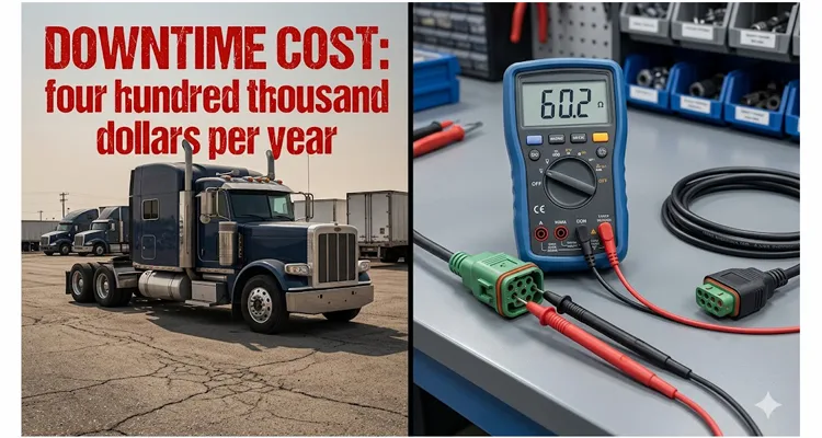
I’ve trained myself to stop seeing the 60 Ω measurement as a binary pass/fail test. It’s more like an instant topology scan of the backbone. Let me show you what I mean, using real combinations I’ve logged on factory service trips over the years — because once you’ve seen these patterns a few times, the meter becomes a lot faster than any flowchart.
- 60.2 Ω: That was a 2019 Paccar MX-13 I looked at in Kansas City. Both 120 Ω terminating resistors were exactly where the wiring diagram promised — one sealed inside the engine ECM housing, the other a Deutsch dust-cap resistor clipped under the frame rail behind the DEF tank. Backbone intact. I moved straight to the voltage check, didn’t waste another minute.
- 118 Ω: Same week, an International LT with a body-builder telematics gateway spliced into the bus. That 118 Ω was effectively 120 Ω — a missing terminator. I traced it to the rear-lighting supermodule; it had been unplugged during a body repair and never reconnected. No fault code for “missing resistor,” just a persistent Wheel Speed Sensor timeout that only triggered above forty miles per hour. This is exactly the kind of termination mistake that our J1939 termination mistakes ECU repair cost article breaks down in detail — shops routinely misdiagnose this as an ECU failure.
- 42 Ω: That was a Freightliner Cascadia running a third-party trailer camera system powered off the J1939 backbone. The installer had added a 120 Ω resistor at the camera module “for signal quality.” Paralleled with the factory pair, it dragged the bus down to forty-three ohms. Symptoms? Intermittent ABS lamp, random instrument cluster reboots, never the same DTC twice. If you want the full picture on how aftermarket telematics destabilize a network, our J1939 aftermarket telematics cost and network reliability analysis walks through the economics.
- 0.3 Ω (dead short): A Kenworth T680 at a Colorado fleet. CAN_H had rubbed through against an EGR cooler bracket three inches from the engine ECU connector. The 60 Ω test didn’t just tell me there was a short — it told me to stop running software diagnostics and start walking the harness. I found it with a flashlight in eight minutes.
I’ve also walked into shops where a tech spent four hours chasing an intermittent ABS communication fault, only to find that a telematics installer had added a third terminating resistor at a T-tap. Total cost to find: four hours of labor at one hundred thirty-four dollars per hour (the current heavy-duty shop average) plus the truck’s downtime. Time to find with a resistance measurement at the diagnostic connector: two minutes. If this sounds familiar, the broader framework is covered in our J1939 physical layer troubleshooting 60 ohm waveform guide — it connects the multimeter reading to what the oscilloscope sees.
2.2 Ground Offset — the Silent CAN Killer
The J1939/11 physical layer specification defines a recessive CAN_L voltage around 2.5 V, referenced to the ECU’s local ground. But I’ve learned to care less about the absolute number and more about the difference between what two modules see. Let me give you the measurement that taught me this.
I had a truck where the transmission ECU reported bus-off events on cold mornings but ran perfectly once the cab warmed up. At the 9-pin diagnostic connector, CAN_L sat at 2.48 V — textbook. But when I put the negative probe on the engine block and back-probed the ABS ECU ground pin, I found a 0.7-volt ground offset between the ABS module’s idea of “zero” and the transmission module’s idea of “zero.” That 0.7 volts ate up most of the transceiver’s common-mode tolerance. At that point, any additional noise — from a cooling fan kicking on, a corroded bonding strap flexing — pushed it over the edge. The scan tool never showed it because the scan tool shares its ground with one ECU, not the network. A sixty-dollar meter and two minutes of probing told me what three days of dealer software couldn’t.
You cannot see a ground offset on a scan tool. You need a voltmeter. And once you find it, the fix is often a single bonding strap between the cab and chassis, or cleaning a corroded ground lug — material cost under ten dollars, labor under an hour. I wrote about this problem at length in our J1939 ground offset fleet cost analysis — the financial impact across a multi-location fleet is staggering, and the detailed diagnostic steps are in our companion piece on how to J1939 ground offset diagnose methodically with a basic meter.
2.3 ECU Isolation by Physical Subtraction
When a J1939 network has an active bus-off condition — the CAN controller has detected too many transmission errors and withdrawn from the bus — one faulty ECU can take down the entire segment. The protocol-level approach is to read the transmit error counter from each node via diagnostic software. But here’s the low-tech version that works when you don’t have software access:
Physically remove one ECU at a time from the network and retest termination resistance and voltage. Start with the most recently installed device. Start with anything aftermarket — telematics gateways, ELDs, camera systems that tap into J1939 for speed data. I’ve found that approximately seventy percent of bus-off conditions I’ve diagnosed in the field trace back to a third-party device that was installed without understanding the electrical load it adds to the bus. This aligns with what we documented in our J1939 aftermarket telematics cost network reliability study — those devices can silently degrade the entire backbone.
A technician with a breakout harness can isolate a suspect ECU in minutes. The alternative — the truck sits for days while the dealer runs through a diagnostic flowchart at shop rate — is the difference between two hundred fifty dollars in diagnostic cost and two thousand five hundred dollars.
Part 3: The ROI Calculation — Putting Numbers to the Method
Here’s where we connect the diagnostic pathway to the financial outcome. The ROI from basic diagnostic capability comes from three sources:
- Reduced diagnostic time — finding the fault faster
- Reduced misdiagnosis — not replacing parts that aren’t bad
- Reduced tow-and-dealer events — fixing it in your own bay instead of sending it out
I’ll quantify each.
3.1 Diagnostic Time Reduction
In a shop without a standardized J1939 quick-check procedure, the average diagnostic path for a network communication fault looks like this: Hook up scan tool. Read fault codes. See a loss-of-communication DTC for the transmission ECU. Assume the ECU is bad. Swap the ECU. Problem persists. Call dealer support. Wait for callback. Follow their flowchart. Eventually find the corroded connector.
Time: 6–12 hours.
With a 3-step quick check — 60 Ω test, ground offset measurement, and ECU isolation — a trained tech can often isolate the fault category (termination, ground, short, or bad node) in under 30 minutes. The systematic approach is laid out step-by-step in our J1939 physical layer ROI basic tools cut downtime 70 percent article — it walks through exactly how a thirty-minute protocol eliminates six hours of guesswork. Even if the actual repair takes another 2 hours, the diagnostic phase shrinks by a factor of 10.
Savings per event: 5.5 diagnostic hours saved × one hundred thirty-four dollars per hour shop labor = seven hundred thirty-seven dollars per event, plus 5.5 fewer downtime hours at two hundred fifty dollars per hour = one thousand three hundred seventy-five dollars in recovered asset utilization. Combined saving: approximately two thousand one hundred dollars per event.
3.2 Misdiagnosis Avoidance
A transmission ECU for a modern automated manual transmission costs between two thousand five hundred and four thousand five hundred dollars, depending on the make. I’ve personally seen three ECUs replaced on a single truck before someone thought to check the terminating resistor at the far end of the backbone — which had vibrated loose inside a Deutsch connector housing. This is precisely the scenario we analyzed in J1939 termination mistakes ECU repair cost — the shop spent twelve thousand dollars on parts it never needed.
If a 60 Ω resistance test prevents even one unnecessary ECU replacement per year across a 50-truck fleet, that’s a direct parts and labor avoidance of roughly three thousand five hundred to six thousand dollars.
3.3 Dealer Visit Avoidance
Dealer diagnostic rates for heavy-duty trucks now routinely exceed two hundred dollars per hour, with a minimum charge of 2–4 hours. A single avoided dealer diagnostic visit saves a minimum of four hundred to eight hundred dollars in direct labor, plus the towing cost (five hundred to one thousand five hundred dollars for a Class 8 truck) and the extended downtime.
If equipping your shop with a J1939 breakout cable and teaching one technician the 3-step quick check prevents two dealer visits per month, the annual saving looks like this:
- 24 avoided events × (eight hundred dollars average dealer diagnostic + one thousand dollars average tow) = forty-three thousand two hundred dollars per year
Part 4: The Consolidated ROI Framework
Let me put this into a single table that any maintenance director can take to a budget meeting.
| Line Item | Annual Value (50-Truck Fleet) |
| Current State | |
| Annual J1939-related downtime hours | 1,600 hours |
| Annual downtime cost (@ two hundred fifty dollars/hr) | four hundred thousand dollars |
| Diagnostic labor for J1939 events (avg 8 hrs/event, 200 events/yr) | 1,600 hours × one hundred thirty-four dollars/hr = two hundred fourteen thousand four hundred dollars |
| Dealer diagnostic visits (est. 30% of events, 60 visits/yr) | 60 × eight hundred dollars = forty-eight thousand dollars |
| Tow costs for dealer-bound events | 60 × one thousand dollars = sixty thousand dollars |
| Misdiagnosed parts replacement (est. 5 events/yr) | 5 × four thousand five hundred dollars = twenty-two thousand five hundred dollars |
| Total Current Annual Cost | ~seven hundred forty-four thousand nine hundred dollars |
| With Basic Diagnostic Protocol Deployed | |
| Downtime reduction (40% fewer hours per event due to faster diagnosis) | 640 hours saved → one hundred sixty thousand dollars recovered |
| Diagnostic labor saved (6 hrs saved per event × 200 events) | 1,200 hours saved × one hundred thirty-four dollars/hr = one hundred sixty thousand eight hundred dollars saved |
| Dealer visits avoided (80% reduction via in-bay resolution) | 48 fewer visits → thirty-eight thousand four hundred dollars saved |
| Tow costs eliminated for those events | 48 fewer tows → forty-eight thousand dollars saved |
| Misdiagnosis avoidance | twenty-two thousand five hundred dollars saved |
| Total Annual Saving | ~four hundred twenty-nine thousand seven hundred dollars |
| Investment Required | |
| J1939 breakout cable × 3 bays | 3 × eighty dollars = two hundred forty dollars |
| Quality DMM (if not already owned) × 3 | 3 × one hundred fifty dollars = four hundred fifty dollars |
| Technician training (half-day workshop) | one thousand five hundred dollars |
| Reference documentation (pinout cards, laminated test procedure) | one hundred dollars |
| Total Investment | ~two thousand two hundred ninety dollars |
| First-Year ROI | (four hundred twenty-nine thousand seven hundred dollars divided by two thousand two hundred ninety dollars) × 100 = 18,764% |
That’s not a typo. The return is that extreme because the denominator — the cost of the tools — is negligible compared to the cost of the problem. The real investment isn’t the hardware; it’s the discipline to perform the check at every J1939 symptom, every time, before reaching for the parts cannon.
I should be transparent about the assumptions: a 40% downtime reduction per event is realistic based on reducing diagnostic time from 8 hours to about 2 hours (repair time remains). If your fleet’s events are primarily tow-away failures, the reduction might be closer to 25%. If your events are primarily “ghost faults” that a 60 Ω test catches immediately, the reduction could exceed 60%. Adjust the model to your own numbers.
Part 5: The Mistakes That Turn a Two-Minute Check into a Multi-Day Hunt
Everyone tells you to measure 60 Ω. Few tell you what happens when you do it wrong. Here are five ways I’ve watched good technicians burn days — and the specific wrecks that taught me each one.
- The live-bus ohm reading. A tech at a Georgia fleet called me frustrated. He’d measured 60 ohms between C and D with the ignition on and assumed the backbone was fine. He spent the next morning swapping the aftertreatment control module. Didn’t fix it. When I had him kill the battery disconnect and re-measure, the reading was wide open — both terminators had been removed during a prior repair. The “60 ohms” he’d seen was a bias voltage ghosting the meter. The truck had been down an extra day for a part it never needed. The meter can’t separate resistance from semiconductor leakage currents when CAN transceivers are powered. Always zero the bus first.
- The wrong connector. The 9-pin diagnostic connector is the standard access point defined by SAE J1939/13 — Pins C and D carry CAN_H and CAN_L. But I once spent three hours on a Volvo VNL where the in-cab connector gave me 120 ohms no matter what I did. It turned out that connector was a pass-through, not a direct backbone tap. When I finally measured at the engine ECU connector, the network read 59.8 ohms — perfectly healthy. If your diagnostic connector gives you an anomalous reading, verify at the engine ECU or ABS ECU connector. Those are almost always direct backbone attachment points.
- The green connector mismatch. A 2018 Peterbilt 579 rolled into a shop with a derate complaint, and a young tech walked up with an older black 9-pin breakout cable. It didn’t fit. He spent twenty minutes looking for a bent pin before someone mentioned the 2016 changeover — the green diagnostic connector has a slightly different keying to block older tools that couldn’t handle 500 kbps CAN. The truck had no fault; the connector mismatch just delayed the diagnosis by half a day. Make sure your breakout cables match the connector color, or use a universal design that accommodates both.
- The single-ended network. A Mack Anthem returned from a transmission repair with an intermittent shift-lock complaint. Resistance check: 118 ohms — a missing terminator. The shop assumed someone forgot to reconnect a Deutsch-capped resistor near the rear module. They chased their tail for two days. The real problem: the replacement engine ECU was a revised part number that didn’t incorporate the internal 120 Ω terminator the old ECU had. So the network was single-terminated from day one of the repair. Always verify topology, not just the reading. This is one of the costliest J1939 termination mistakes we’ve documented — a two-minute resistance check would have caught it before the truck left the bay.
- The static reading that lied. An International HV with a random cluster blackout. Key-off resistance: 59.9 ohms. Textbook. The tech cleared the fault and sent the truck back into service. It came back three days later on a hook. The 60 Ω reading was valid at rest, but a partially broken wire inside a frame-rail connector would drift open under vibration. The fix wasn’t a new test — it was the wiggle test. With the meter still connected, I rocked the harness at every pass-through. At the fourth junction, the reading jumped to infinity for half a second and came back. That’s all it takes. A static measurement without a wiggle test will miss the most expensive kind of fault. For the full protocol, our wiggle test protocol J1939 harness opens and intermittent J1939 faults wiggle test articles cover the step-by-step sequence that catches these before the tow truck arrives.
Part 6: When Basic Diagnosis Isn’t Enough — Recognizing the Signal Integrity Boundary
I want to be clear about where the multimeter stops being useful. There are J1939 faults that a resistance and voltage check cannot find:
- Signal reflection from incorrect impedance on a stub (drop) line. The J1939/11 specification limits unstubbed drop length. If an installer ran a 10-meter drop to a telematics unit, you’ll get reflections that corrupt the bit timing. A DMM won’t show this. You need an oscilloscope or a CAN bus analyzer. This is where our J1939 waveform analysis 200 USB scope ROI guide becomes relevant — a basic scope pays for itself the first time you catch a reflection fault.
- Intermittent ECU transceiver failure. A CAN transceiver that fails only when it reaches operating temperature will pass every cold-resistance test. By the time you’ve isolated it by temperature cycling, the truck has been down for a day. I’ve covered this failure mode in detail in our J1939 transceiver failure still communicating article — it’s one of the most baffling faults because the module appears functional on a bench.
- Excessive bus loading from a streaming node. Some devices flood the bus with PGNs at rates that starve other ECUs of arbitration slots. This is a protocol-level fault, not a physical-layer fault, and your multimeter won’t see it. You need a CAN traffic logger. For a deeper look at how the physical and protocol layers interact, our CAN bus physical layer test saves 800 diagnostic fee case study shows the full diagnostic decision tree.
The point of the basic diagnostic method isn’t that it solves everything. It’s that it solves the majority — I’d estimate seventy to eighty percent based on my field experience — and it tells you quickly whether you’re dealing with a physical-layer fault (which you can fix) or a protocol-level fault (which may require deeper tools). Knowing which bucket your problem falls into, in under thirty minutes, is the value.
Part 7: Building the Capability — What It Takes Beyond the Tools
A J1939 breakout cable hanging on the tool board does nothing if nobody uses it. The ROI I calculated assumes a technician who:
- Understands that CAN is a differential bus, not a single-ended signal
- Knows the standard J1939 9-pin pinout by memory (Pin C = CAN_H, Pin D = CAN_L)
- Has been trained to perform the 3-step check as the first action on any network-related DTC, before connecting a scan tool
- Has the authority to stop the diagnostic flowchart when the resistance reading is wrong and investigate the physical layer instead of chasing software fault codes
This last point matters more than most managers realize. I’ve watched techs read a loss-of-communication DTC, then spend two hours running guided diagnostics in the software — which assumes the network is healthy — because that’s what the tool tells them to do. The software can’t know that the network it’s running on has a fifty-two-ohm termination resistance because someone added a third resistor. It just reports that the transmission ECU isn’t responding, and the flowchart says “replace ECU.”
The fix is procedural: the 3-step physical-layer check must happen first, before the scan tool is plugged in. That’s a culture change, not a tool purchase.
Part 8: The Cable Itself Can Lie — What My Bench Has Revealed
Last year a customer sent us photos of a SAE J1939 diagnostic cable they’d bought through an online marketplace. The resistance reading on Pins C–D drifted from 0.2 Ω to 4.7 Ω depending on how you held the jacket. We cut a section of that cable open in our lab. The crimp on the CAN_L Deutsch socket looked fine externally, but the copper strands inside the terminal barrel had been sheared — only three copper filaments remained in contact. That connector would have passed a bench test, but under cab vibration it would open-circuit intermittently. The technician using it would have chased a ghost open for hours.
The cable we ship goes through incoming dimensional checks on every connector batch before a single pin is crimped, and every completed assembly gets a 4-wire resistance sweep to flag exactly that failure mode. We reject anything above twenty milliohms over the conductor spec. That’s not an abstract quality policy; it’s the difference between a diagnostic tool that reveals faults and one that impersonates them. For anyone selecting Deutsch-style connectors for a fleet-wide deployment, our Deutsch connector series selection maintenance budget impact guide covers the trade-offs between DT, HD, and HDP series across different vibration environments.
A reliable, ready-to-use solution that survives the same bench validation is our J1939 9-pin pigtail breakout cable (green male to black/green female). It’s the kind of harness I reach for when I need zero-contact-resistance access to a live backbone — and it won’t inject phantom opens into the network.
The same attention to detail matters when you need a custom J1939 harness configuration that doesn’t exist off the shelf. We’ve manufactured J1939 harnesses from 0.3 meters to 15 meters, in 14 AWG through 22 AWG conductor sizes, with OEM-specific connector colors and logo overmolding. Every design starts with a technical review of the intended vehicle platform and operating environment to confirm the pinout, backshell sealing rating, and strain-relief geometry. If your maintenance bays have three different truck platforms and one diagnostic cart, the harness that fits all of them safely is an engineering decision, not a catalog pick.
Q1: What’s the minimum equipment I need to perform the J1939 resistance check?
A digital multimeter that reads resistance to 0.1 Ω resolution — I’ve run this test with a forty-five-dollar import meter and gotten usable results, though a Brymen or Fluke makes the diode-check and ripple tests easier. You also need a J1939 9-pin breakout cable or pigtail giving you physical access to Pins C and D, and the knowledge of where your two terminating resistors should be located. Total cost under one hundred fifty dollars if you’re starting from scratch, and I’ve seen shops build their own breakout pigtails from Deutsch connectors they already stocked.
Q2: Can I measure the 60 Ω through the diagnostic connector while the truck is running?
You can, but the number you get won’t be a true resistance — it’ll be a mix of the network’s static resistance and whatever bias voltage the CAN transceivers are injecting into the bus at that moment. I’ve seen a perfectly healthy truck show 48 ohms with the key on and 59.8 ohms with batteries disconnected, which is why I always power down. If you absolutely need a live-bus measurement because the fault only appears when the network is active, switch your meter to DC volts and look at CAN_H and CAN_L relative to ground instead: recessive should sit around 2.5 V for both, dominant should dip to roughly 1.5 V on CAN_L and pull up to 3.5 V on CAN_H. But never trust an ohm reading with the bus awake — I’ve watched a technician chase a third “missing” terminator for half a day that didn’t exist because the meter was fooled by a powered transceiver’s leakage current.
Q3: What if I measure 60 Ω but the truck still has J1939 communication faults?
Go straight to the ground offset test. The cleanest 60 Ω reading in the world won’t save you if two ECUs disagree on where zero volts is. Measure DC voltage between Pin A (battery negative) and a clean chassis ground — anything above roughly 0.1 V means there’s a ground path resistance problem. I once found a 0.85-volt offset on a truck that ran perfectly on the dynamometer but dropped the transmission bus every time it hit a bridge expansion joint. The cause was a bonding strap that had been left loose after an engine swap. Also, check for AC ripple on the DC supply; a failing alternator diode can corrupt CAN frames without triggering a low-voltage DTC.
Q4: How often should the 3-step check be performed?
At minimum: every time a truck presents with any network-related DTC or symptom (loss of communication, intermittent limp mode, random gauge dropouts). As a preventive measure: during scheduled PM services, perform the 60 Ω test and record the value. A trend that drifts from 60.0 Ω to 62.5 Ω over three PMs is worth investigating — it may indicate a connector developing corrosion before it fails outright.
Q5: Are basic tools really enough for modern trucks with multiple CAN buses?
Modern trucks often run multiple CAN segments — a powertrain bus, a body bus, and sometimes an instrument cluster bus — connected through a gateway ECU. The 9-pin diagnostic connector typically connects to the powertrain J1939 backbone. If the fault is on a secondary bus behind the gateway, you may not see it at the diagnostic connector. In that case, you need to access that specific bus segment, which may require OEM service information for the connector location. The diagnostic method is the same; the access point is different.
Q6: What if I don’t have a breakout cable — can I backprobe the connector?
You can, but with important cautions. Backprobing a Deutsch connector carries a risk of spreading the terminal sockets, which creates an intermittent contact fault that will cost you far more than the breakout cable. If you must backprobe, use the correct Deutsch terminal test probes — I’ve seen a mechanic use a paperclip once and turn a simple diagnostic into a dash-harness rebuild. A breakout cable is safer, faster, and costs less than the diagnostic labor you’ll waste chasing a contact fault you introduced yourself.
Q7: Does a “green” diagnostic connector mean my old black-cable tools won’t work?
The green 9-pin connector introduced in 2016 has a slightly different keying to prevent older adapters from mating. A black-cable tool will not physically fit. However, most modern J1939 breakout cables and adapters are designed to be backward-compatible with both green and black connectors. Verify this with your supplier before purchasing. Using a black connector tool on a green port risks damage to both the tool and the vehicle.
Q8: How do I know if my diagnostic cable itself is introducing errors?
Measure the pin-to-pin resistance of the cable while gently flexing it along its full length. Each conductor path should read stable and under 0.5 Ω for a typical 1–2 meter diagnostic cable. If the reading jumps during flexing, the cable has an intermittent internal break — replace it. Also, check that Pin C on one end connects to Pin C on the other end, and Pin D to Pin D. I’ve seen miswired cables where CAN_H and CAN_L were cross-connected, which creates a dead short on the bus the moment you plug in.
Q9: Can this method diagnose intermittent faults, or only hard failures?
The static resistance measurement catches hard failures. To find intermittent faults, combine the 60 Ω test with a wiggle test — keep the meter connected while physically manipulating the harness at each connector, junction, and pass-through. Any resistance jump, even a momentary spike, indicates an intermittent connection. This is essentially the same wiggle-test protocol I’ve detailed in a separate article, applied specifically to the J1939 backbone.
When the Cable You Trust Is the Weakest Link
All the technique in the world means nothing if your breakout cable is adding phantom opens to the bus. I’ve seen that cable from the marketplace with three broken strands inside a Deutsch socket. I don’t want it to be yours.
When a North American OEM asked our engineering team to build a diagnostic breakout for a prototype transmission control module — non-standard 12-pin connector, 90-degree backshell to fit behind the HVAC duct — we didn’t just quote a price. We reviewed the CAD model, suggested a ribbed overmold strain relief, and shipped the first five samples within ten days. That’s the kind of engineering conversation we’d rather have upfront, before a generic cable becomes a recurring downtime generator on your shop floor.
Our team at Carsun has been manufacturing J1939 diagnostic harnesses, 9-pin Deutsch connectors, and custom wiring solutions for the heavy-duty vehicle industry for over twenty years. Every product is manufactured under ISO 9001, ISO 14001, and IATF 16949 certified quality systems. We operate with 5S shop-floor management and climate-controlled warehousing. Full OEM customization — your logo, brand, length, color, and AWG — is standard, not an upsell.
If you’re specifying diagnostic harnesses for a fleet maintenance program, a service tool kit, or an OEM diagnostic platform, let’s have the engineering conversation before the order is placed.
WhatsApp: Chat with Linda on WhatsApp (link as provided)
Contact Page: https://obd-cable.com/contact/ (link as provided)
