

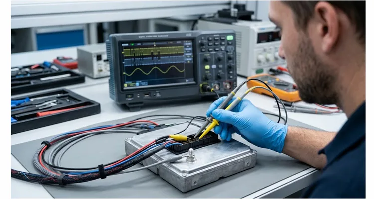
On a 12 V bench last quarter, a body-domain controller was dropping CAN frames at idle, but only after the engine had been running for eight to ten minutes. Key-on, engine-off: clean recessive and dominant levels. Engine at 1,500 rpm with electrical load applied: the bus waveform developed a slow envelope, and the node missed frames in bursts. The engineer had already replaced the transceiver once. The replacement behaved the same way.
He did not have a differential probe. He had been trying to capture the alternator AC ripple with a single passive probe, ground clip on the module chassis, tip on CAN_H. The trace showed amplitude, but the amplitude did not match the scan-tool behavior. The scope was telling a partial story.
A differential probe is the correct instrument. That is not in dispute. But the bench does not always have one, and the node does not stop dropping frames while the purchase order clears. The method below produces a defensible differential measurement from two passive probes. The inspection that follows the subtraction decides whether that trace is valid. The waveform reading that closes the loop separates a rectifier fault from an artifact of the probing setup.
The ground clip is not a reference. It is a short-circuit path.
A passive oscilloscope probe’s ground clip is bonded to the scope chassis and, through the mains safety ground, to earth. CAN_H and CAN_L are not earth-referenced nodes. The ISO 11898 physical layer defines the bus as a differential wired-AND pair referenced to the transceiver’s local ground, not to chassis earth. The receiver specification for a classic high-speed CAN transceiver requires correct recessive and dominant detection with common-mode input voltages inside the −2 V to +7 V window required by ISO 11898. Fault-protected transceivers may extend that range to plus or minus thirty volts or beyond, but the extension is part-dependent and is not a property of the bus itself. When the probe ground clip touches CAN_L, the clip does not create a differential measurement. It forces CAN_L toward the scope chassis reference through the probe shield. If the device under test already has an earth bond through a power supply, a charger, or a test rack, that path carries current. The displayed waveform is corrupted by the ground-loop voltage, and the CAN_L node is exposed to a short-to-earth condition through the probe.
The first constraint is therefore not a technique. It is a prohibition: no ground clip on either side of the differential pair. The reference point is the module ground or the battery negative terminal, not CAN_H or CAN_L.
Pseudo-differential measurement: two probes, one reference, no ground clips on the bus
The method that works without a differential probe is a two-probe subtraction. Two single-ended probes are referenced to the same module ground. Channel 1 tip goes to CAN_H. Channel 2 tip goes to CAN_L. The scope’s math function subtracts channel 2 from channel 1. The result approximates the differential signal.
Mechanical constraints for a two-probe pseudo-differential measurement
The mechanical constraints are fixed. Both probes must be the same model and the same attenuation setting. The scope channels must use the same volts per division. Both channels must be AC-coupled and bandwidth-limited to 20 MHz bandwidth limit. The probe ground clips must both terminate at the module ground or battery negative, twisted together where the probe geometry allows it. The probe tips must touch only CAN_H and CAN_L, with no ground clip on either bus line. The probe leads should be routed away from the alternator B+ cable and any injector or ignition wiring, and twisted loosely together to reduce loop area.
These constraints are not a recipe for equivalence with a true differential probe. They are the conditions under which the subtraction is usable at all. Probe mismatch leaves a residual common-mode component in the subtracted trace. A one percent gain mismatch between channels lets roughly one percent of the common-mode signal appear as a differential error. On a bus carrying several volts of common-mode ripple, that leak can be tens of millivolts—enough to make a borderline pass or fail decision unreliable.
The check that validates the math trace: verify the common-mode envelope before trusting the subtraction
A subtracted trace can look clean and still be invalid. The math function reports the difference between the two single-ended measurements. It does not report whether either measurement is within the probe’s safe input range or within the transceiver’s specified common-mode range.
The single-ended inspection that separates a valid trace from a plausible one
Before accepting the math trace as a representation of the differential signal, turn the math function off and inspect each single-ended channel against ground. If either CAN_H or CAN_L is sitting at a common-mode envelope level outside the probe’s rated input window, the subtracted trace is not a valid measurement of the bus. The correct response at that point is an isolated input or a true differential probe with adequate common-mode range, not a more careful subtraction.
This check is the operational boundary between a defensible fallback method and a trace that lies. The pseudo-differential measurement measures the ripple that is present on a bus that is still communicating. It does not rescue a bus whose common-mode reference has already collapsed. The same common-mode mechanism is documented in common-mode voltage that kills J1939 communication, and the bench check above is how you catch it before it is misread as a transceiver failure.
ISO 16750-2:2023 changed the pass/fail line. The bench has to separate waveform degradation from threshold movement.
Clause 4.3.2 of ISO 16750-2:2023 specifies a maximum peak-to-peak ripple amplitude of 250 mV for 12 V nominal systems, down from 300 mV in the previous revision, and 500 mV for 24 V systems, down from 600 mV, under full-load, warm-condition testing at 25 degrees Celsius ambient. The standard explicitly requires oscilloscope-based verification rather than a multimeter RMS reading for compliance assessment.
Separating ripple degradation from a moved ISO 16750-2:2023 threshold
The operational consequence is not a new waveform. A unit that was passing under the old 300 mV limit can fail under the new 250 mV limit at the same amplitude, the same rpm, and the same load. The bench technician’s task is to distinguish a real increase in alternator AC ripple from a threshold that moved beneath a stable waveform. A diode fault that raises amplitude from 220 mV to 270 mV is a degradation. A waveform that sits at 260 mV today and sat at 260 mV last year is a threshold shift. The scope trace looks the same in both cases. The maintenance decision does not.
Reading the rectifier from the subtracted trace: amplitude is secondary to morphology and phase
Once the trace is trustworthy, the waveform stops being a number and becomes a fault-isolation instrument. A healthy three-phase alternator with a six-diode bridge produces a ripple whose fundamental is tied to shaft speed and whose peaks are approximately symmetric.
Phase-stable asymmetry versus wandering asymmetry in the subtracted trace
A single open diode removes one of the six rectification events per electrical cycle. On the scope, the signature is not simply a larger sinusoid. It is a phase-stable asymmetry: a periodic downward excursion that is deeper than the surrounding valleys, and its phase relative to the trigger reference remains stable from acquisition to acquisition as long as rpm and load are held constant. The fundamental frequency itself does not shift, because the shaft speed has not changed; what changes is the shape within each cycle. The old shop shorthand calls this an asymmetric wave or a long downward tail, but the actionable parameter is the phase-stable asymmetry at a fixed operating point.
A stator winding insulation fault behaves differently at the same measurement plane. The fundamental becomes unstable relative to the trigger, and the RMS value of the ripple can climb while the average DC voltage remains normal. The downward excursions do not maintain a fixed phase relative to shaft position. If the asymmetry is phase-locked and the fundamental is stable, the bridge is the first suspect. If the asymmetry wanders and the RMS rises without a corresponding DC shift, the stator winding insulation fault is the first suspect.
A low-frequency envelope that breathes at a few hertz, with the rectifier ripple riding inside it, points away from the diodes and toward the regulator feedback loop. The corrective action changes from a bridge replacement to a regulator swap. A DMM reading a single AC RMS number cannot make this distinction. The time-domain waveform can, provided the measurement setup has not already contaminated the shape.
Comparison of measurement approaches: what each method captures and where it stops
| Measurement approach | What it captures | What it misses | Common-mode verification required? | Principal risk |
| DMM on AC volts, B+ to case | A single RMS number | Waveform asymmetry, phase stability, intermittent dropout | Not applicable; single-ended by construction | Low, if the meter blocks DC in AC mode |
| Single passive probe, ground clip on CAN_L | A waveform contaminated by ground-loop and common-mode error | True differential amplitude; safe operation on a non-earth-referenced bus | Not possible; the ground clip has already altered the circuit | High: ground clip can short CAN_L toward earth through the probe |
| Two-probe subtraction, grounds tied at module ground | Differential ripple within the probes’ matched limits and the scope’s input range | Ripple that pushes common-mode outside the probes’ rating; very high-frequency content above the probe and scope bandwidth | Required before the math trace is trusted | Low, if the single-ended common-mode envelope is inspected first |
| True differential probe with adequate common-mode range | The cleanest differential view, including common-mode excursions within the probe’s window | Still limited by probe bandwidth and common-mode range; availability and cost | Recommended as a cross-check, but the probe’s CMR specification defines the validity boundary | Low, when used within ratings |
Five mistakes that invalidate the trace before the first capture
- The most common mistake is clipping the probe ground to CAN_L to see something. The resulting waveform is usually plausible enough to be believed, and it is usually wrong because the ground clip has created a return path the bus was not designed to tolerate.
- The second is using two probes with different attenuation settings or different models and assuming the subtraction will cancel the common-mode component. It cancels some of it. The residual can exceed the ripple you are trying to measure.
- The third is leaving the 20 MHz bandwidth limit off. The trace then includes the regulator’s switching residue and the probe ground-lead resonance, not the rectifier ripple. The measurement becomes a study of the probe, not the alternator. A 50 MHz versus 100 MHz scope bandwidth comparison explains why the limit is not the same as hiding information.
- The fourth is measuring only at the battery terminals and assuming the CAN bus sees the same amplitude. The bus sees the ripple through the shared ground-return impedance, the connector contact resistance, and the common-mode path. Even a minor 0.3 V ground offset can amplify this effect and take down the backbone. A difference between the battery-post amplitude and the transceiver-end amplitude is diagnostic information: it indicates how much common-mode ripple the harness impedance and connector impedance are converting into differential error.
- The fifth is trusting a single capture at one engine speed. A diode fault that is invisible at idle can become a phase-stable asymmetry at 2,000 rpm under electrical load. Sweep the rpm range and apply the load the system is specified to carry. The same rpm-dependent behavior appears in alternator ripple captured at 1,400 rpm on a J1939 network, and it is why a single idle capture is not a pass criterion.
Where the harness impedance enters the ripple path, and why salt spray and PPAP belong in the same paragraph
The alternator is the source. The bus does not see the alternator directly. It sees the ripple through the ground-return impedance, the connector contact resistance, and the common-mode impedance of the twisted pair.
Why ASTM B117 salt spray and PPAP Level 3 belong in a harness impedance discussion
A connector whose contact resistance rises after environmental exposure changes that path. Neutral salt spray testing per ASTM B117 for 96 hours is a standard gate for underhood and chassis connectors because it exposes plated terminals to a five percent sodium chloride fog at 35 degrees Celsius and reveals corrosion mechanisms that a bench continuity check will miss. The failure mode that matters for ripple measurement is not an open circuit. It is a resistive shift in the ground return. That shift changes the common-mode impedance the bus presents to the alternator, and it can convert a ripple amplitude that was previously within the transceiver’s window into a differential error at the receiver.
PPAP Level 3 documentation is the evidence that this impedance will not drift between production lots. In automotive wire harness programs, Level 3 is the common submission baseline: a Part Submission Warrant with the full supporting package, including dimensional results, material certifications, process flow, PFMEA, control plan, and capability data. The purpose of that package in a ripple investigation is not to satisfy a purchasing checklist. It is to establish that the connector and terminal geometry that produced the measured impedance on the first article will produce the same impedance on the next build, after the same salt-fog and thermal exposure. A ripple problem that appears only after a winter of road salt is not an alternator problem alone. It is a system harness impedance problem, and the harness is part of the system. The factory evidence behind that claim sits in the IATF 16949 cable-assembly traceability record, the ISO 14001 registration, the IATF 16949 certification milestone, and the certificate scope recorded under 1298-2.
Confirming the measurement is real and the repair is complete
Before accepting a pass, inspect the single-ended common-mode envelope on both channels. If either line is outside the probe’s safe input range or the transceiver’s specified common-mode range, the subtracted trace is not a valid pass criterion, regardless of its appearance.
Baseline comparison and post-repair verification
Compare the unit under test against a known-good node on the same bench, at the same rpm and electrical load, using the same probe pair, ground point, and bandwidth setting. An absolute amplitude without a baseline is not actionable, because manufacturing tolerance between alternators moves the baseline.
After the repair—diode replacement, stator swap, or regulator change—repeat the measurement at the same operating points. The phase-stable asymmetry should be absent. The peak-to-peak amplitude should sit inside the ISO 16750-2:2023 window for the system voltage. If the amplitude drops but the asymmetry remains phase-locked, the bridge may have more than one degraded diode, or the stator may have a developing fault that the diode replacement did not address.
If the common-mode envelope is already outside the transceiver’s window
The pseudo-differential measurement buys a defensible measurement when a differential probe is unavailable. It does not extend the common-mode range of passive probes. If the single-ended inspection shows CAN_H or CAN_L outside the transceiver’s specified common-mode range, the next question is not a measurement question. It is a design question: is the ground return adequate, is the transceiver’s common-mode range appropriate for the alternator’s ripple profile, and is the harness impedance behaving the way the schematic assumes it is.
Those are the questions we work through with test-bench engineers and OEM harness teams. If you are validating a CAN physical layer and need a harness or connector that holds its harness impedance through salt-fog exposure, thermal cycling, and alternator AC ripple—or if you need PPAP Level 3 documentation that a tier-one quality group will accept without a submission loop—use the WhatsApp link below to describe the node, the engine speeds where the fault appears, and the measurement setup you are using. You will reach an engineer.
Chat with an engineer on WhatsApp
If you prefer to send a scope capture, a harness drawing, or a list of the load points where the fault reproduces, the contact page goes to the same engineering desk.
FAQ
My math trace shows a clean differential ripple, but the node still drops frames. What is the scope not showing me?
The subtraction cancels the common-mode component; it does not report whether that component is within the transceiver’s input window. Inspect each single-ended channel against ground. If CAN_H or CAN_L is moving outside the part’s specified common-mode range before the subtraction, the receiver can fail even when the math trace looks acceptable.
Why does the same alternator produce a different ripple amplitude on two different benches?
Ground-return impedance and probe mismatch. A bench with a longer ground path or a different earth bond converts more common-mode ripple into differential error. Compare the single-ended common-mode envelope on both benches before comparing the subtracted amplitudes.
Can I use a battery-powered scope to avoid the ground-clip problem?
A battery-powered scope removes the mains earth path, but the probe ground clip still bonds the channel reference to the scope chassis. The safer rule remains: no ground clip on either side of the differential pair, and both probe grounds tied to the module ground. If the scope chassis is not earth-referenced, the clip does not create the same earth-loop path, but it still forces the probed node to the scope’s reference.
The waveform shows a clean sinusoid at the ripple fundamental. Is that a diode fault?
A symmetric sinusoid tied to shaft speed can be normal rectifier ripple, especially at light load. Diode faults typically introduce a phase-stable asymmetry within the cycle—one downward excursion deeper than the surrounding valleys, or a flat-topped half-cycle. Compare the morphology at the same rpm and load against a known-good node before replacing the bridge.
Why did the ripple amplitude increase after a replacement alternator was installed?
Diode forward-voltage tolerances and stator winding resistance vary between units, even within the same specification. A replacement can sit at a different point in the manufacturing distribution. Verify the replacement’s amplitude and morphology at the same load and rpm as the original, and confirm that the regulator variant matches the vehicle’s electrical architecture.
Does a CAN FD bus tolerate the same ripple amplitude as a classic high-speed CAN bus?
CAN FD’s higher data-phase rate makes the receiver more sensitive to timing jitter and eye closure. The 2023 ISO 16750-2:2023 tightening to 250 mV peak-to-peak for 12 V systems reflects, in part, the adoption of CAN FD and high-sensitivity ADAS front-ends, whose analog input stages can show measurable degradation above 180 mV peak-to-peak in laboratory immunity testing. If the node is CAN FD, treat 250 mV as the working ceiling for a 12 V system.
How does salt-fog exposure on a connector change a ripple measurement?
Corrosion raises contact resistance and can create intermittent opens in the ground-return path. That changes the common-mode impedance the bus presents to the alternator AC ripple. A connector that passes continuity on the bench can still shift the ripple amplitude at the transceiver after environmental exposure. A 96-hour ASTM B117 gate and PPAP Level 3 capability data are the evidence that the impedance will not drift between lots.
What is the most common reason a pseudo-differential trace looks noisier than either single-ended channel?
Probe mismatch. When the two channels do not have matched gain, phase, and input capacitance, the subtraction leaves a residual common-mode component that appears as noise. Compensate both probes, use the same model and attenuation, and inspect the single-ended common-mode envelope. If the residual is still high, the common-mode disturbance may be large relative to the differential signal, which is itself diagnostic information.
Can a DMM AC reading replace the scope for a production pass or fail gate?
Not for ISO 16750-2:2023 compliance. The standard requires oscilloscope-based verification because the DMM reports a single RMS number and cannot distinguish waveform asymmetry, phase stability, or a diode fault that produces a borderline RMS value with a clearly abnormal shape. The DMM is useful for screening. It is not a substitute for the time-domain waveform at the transceiver.
