

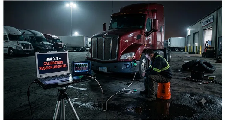
Three weeks ago I found myself sitting on an overturned five-gallon bucket in a fleet yard outside Salt Lake City, staring at a laptop screen that kept flashing the same maddening message: “Timeout – Calibration Session Aborted.” The truck was a 2019 Peterbilt 579 with a Cummins X15. The adapter was a name-brand RP1210 device. The J1939 cable was straight out of the package. Everything should have worked. It didn’t.
That night cost me six hours I’ll never get back. The root cause had nothing to do with a faulty cable, a bad connection, or even the diagnostic software. It was something far more insidious: a mismatch between how the ECU’s task scheduler handled incoming CAN frames and the repetition rate the tool was pumping them out at.
I’ve since seen the same pattern on a Detroit DD15 that refused to take a parameter update, a Volvo D13 where the aftertreatment reset would randomly drop out, and a John Deere 6135 marine engine that a customer swore was “bricked.” Every single case traced back to the same underlying mechanism. I’m writing this down so you don’t have to burn your own six-hour hole in a fleet yard somewhere.
The moment you realize the cable isn’t the problem
The symptom is always the same: you’re mid-session, uploading a calibration file or sending a lengthy dataset over J1939 transport protocol, and the tool throws a phantom timeout. Sometimes it happens at twelve percent. Sometimes at eighty-seven. Sometimes the first attempt goes through fine and the second one fails. You swap the cable. You check the terminating resistors—both of them, because someone always forgets the one buried behind the dash. You reseat the Deutsch connector even though it was already clicked in solid. You downgrade the software, upgrade the software, try a different laptop. None of it changes anything.
Here’s the telltale sign that sets this apart from a genuine physical-layer fault: you hook up a CAN analyzer and expect to see a flurry of error frames or at least a passive-error flag popping up—something that says “I’m broken.” Instead, you get a clean, disciplined conversation that just… stops. Like the ECU finished its sentence and decided it had nothing else to say. On a scope, the differential voltage never collapses. The waveforms are textbook. Yet the session dies.
What’s actually happening is that the ECU’s internal message-handling routine hasn’t crashed—it’s deferred. The microcontroller inside the ECU runs a real-time operating system with a fixed task schedule, a concept well-covered in the CAN bus architecture documentation. The CAN controller hardware has its own receive buffers, usually 16 or 32 mailboxes depending on the chip. When those buffers fill up faster than the application software empties them, the ECU discards incoming frames silently. From the tool’s perspective, the ECU has gone silent. From the ECU’s perspective, it’s still obediently cycling through its scheduler’s priority table.
What’s really going on inside the ECU
To understand why this happens on some engines and not others, you have to look at what happens inside the ECU after a connect message is received. J1939 transport protocol sessions—whether BAM broadcasts or RTS/CTS handshakes—require the receiving node to process each data packet and either assemble the multi-frame message or send a flow-control acknowledgment.
The application task that handles this is rarely the highest-priority thread in the ECU. On a typical heavy-duty engine controller, the task list looks something like this:
| Priority | Task | Max period |
| 1 | Injection timing calculation | 100 µs |
| 2 | Turbo actuator control loop | 500 µs |
| 3 | CAN transmit scheduling | 1 ms |
| 4 | CAN receive / TP processing | 5 ms |
| 5 | Diagnostic session handler | 10 ms |
| 6 | Non-critical housekeeping | 50 ms |
The “CAN receive / TP processing” task runs every 5 milliseconds on many controllers. That means the ECU application layer polls its hardware mailboxes every 5 ms and processes whatever it finds. If your diagnostic tool is blasting out consecutive transport-protocol frames at a 1-millisecond interval—which some tools do, because the J1939 specification permits tight frame spacing on a 250 kbps bus—the ECU’s receive buffers will hold up to 32 frames. At a 1 ms rate, those 32 frames arrive in thirty-two milliseconds. The application task won’t visit the mailboxes for another 5 milliseconds after the first frame lands. That sounds like plenty of margin.
Now factor in an engine running at 1400 RPM under load. The injection and actuator tasks start demanding more CPU time. The scheduler stretches. The “5 ms” task slips to seven, then nine, then eleven milliseconds. This is a classic real-time scheduling problem: when higher-priority threads consume more CPU time, lower-priority tasks suffer scheduling jitter and miss their deadlines. At that point, the buffers overflow. The ECU drops a transport-protocol data frame. The tool, which has been counting sequence numbers, never sees the missing frame and eventually times out the session.
The critical parameter is the repetition rate—the spacing between consecutive data frames on the bus. If your tool lets you adjust it, you can solve the problem. If it doesn’t, you’re at the mercy of whatever setting the developer baked into the firmware.
What makes this a genuine trap is that the same cable, same tool, and same file might work perfectly on a Cummins CM2350 that happens to have a newer scheduler build, and fail on a CM2350 that received a different firmware revision during its last dealer visit. The calibration file is identical. The bus conditions are identical. The difference is entirely inside the ECU’s task timing.
The scheduler differences nobody documents
Through trial and error—and a lot of CAN logs I’ve collected over the past three years—I’ve cataloged how different engine families behave. None of this is published by the OEMs. You either learn it the hard way or you hear it from someone who did.
Cummins CM2350/X15 (2017–2022): The older firmware revisions running on the CM2350B showed a distinct sensitivity to frame spacing below 2.5 milliseconds during calibration uploads. Newer CM2450-based X15 controllers tolerate 1.5 ms without issue. If you encounter a phantom timeout on a truck that hasn’t had a firmware update in three or four years, widen the gap to five or six milliseconds and watch the problem evaporate.
Detroit DD15/DD16 (GHG17 platform): Detroit’s ACM and CPC modules communicate over a private CAN segment, and during a reprogramming event on the CPC, the gateway task that forwards J1939 frames to the private bus introduces an additional one-to-three-millisecond jitter. I’ve measured inter-frame gaps on the public bus that look like a clean 3 ms, but on the private side they’re arriving with 1.2 ms bursts separated by 6 ms gaps. The CPC’s receive buffer is smaller—sixteen mailboxes—and it overflows quickly. The fix here is not just widening the tool’s repetition rate but also reducing the block size: drop from the J1939-21 default of 16 packets per CTS to 8 or even 4.
Volvo D11/D13 (EPA 2017): Volvo’s engine ECU runs a Time-Triggered CAN schedule internally. Their application-layer TP handler is only called in the synchronous time slot, which occurs every 10 milliseconds regardless of bus activity. If your tool sends a flow-control CTS and then immediately begins transmitting data frames before the ECU’s next time slot, the ECU will miss the first three or four frames. The tool retries; the ECU eventually responds to the retransmitted frames; the cycle looks fine—until it isn’t. The solution is a slower, patient handshake.
John Deere PowerTech (marine and off-highway): Some PowerTech controllers implement J1939 diagnostics through a gateway from an internal ISO 11898-2 engine bus to the external service connector. The gateway is surprisingly low-priority and doesn’t buffer more than eight diagnostic frames. I once spent a full day on a dock in Louisiana because someone’s “fast mode” upload setting tried to push frames at 800-microsecond spacing. The fix was embarrassingly simple once I figured it out: set the tool’s minimum inter-frame spacing to 10 milliseconds and walk away to get coffee while the calibration loaded.
A step-by-step method that actually finds the phantom J1939 calibration timeout
I’ve developed a structured diagnostic workflow that catches this class of phantom J1939 calibration timeout in under an hour, without needing to call an OEM field engineer. It works whether you’re a fleet technician, an independent shop owner, or a calibration developer testing new files.
Step 1: Rule out the physical layer before chasing a phantom J1939 timeout
Don’t just wiggle connectors. Measure. Put a multimeter across CAN high and CAN low with the bus powered off and all nodes connected. You should see sixty ohms—two 120-ohm terminating resistors in parallel. If you see 120 ohms, you’re missing a termination. If you see something bizarre like 47 ohms, you have a third resistor somewhere or a partially damaged transceiver.
Next, power up and check for dominant-state voltage. CAN high should sit around 2.5 to 3.5 volts relative to ground; CAN low should mirror at 1.5 to 2.5 volts. If the recessive state isn’t clean, you’ll have reflection problems that mimic scheduler dropouts. A good-quality shielded J1939 cable with molded Deutsch connectors will save you from spending an afternoon convincing yourself the problem is intermittent when it was actually a reflection from an unshielded six-foot whip you borrowed from the shop next door.
Step 2: Log CAN bus traffic to catch the exact moment of a J1939 calibration timeout
You don’t need a twenty-thousand-dollar Vector setup. A PEAK PCAN-USB or a Kvaser Leaf Light with a free copy of SavvyCAN or BusMaster will do the job. You’ll also want a J1939 breakout cable to tap into the bus without interrupting communication. Capture a trace that spans the moment the timeout hits. Look at the sequence-number field in the transport-protocol data packets. Is there a gap? Did the ECU send a negative acknowledgment or a “clear to send” with a window size that the tool ignored? The log almost always tells you exactly where the conversation broke down.
Step 3: Adjust the inter-frame spacing—the single most effective repetition rate fix
If your diagnostic software exposes a timing profile (many engineering-level tools do), bump the inter-frame spacing from the default—usually around 1 or 2 milliseconds—up to 5 milliseconds and re-test. If that doesn’t hold, go to eight. On a Detroit CPC, also drop the maximum block size to eight frames. On a Volvo, set the “CTS response delay” to at least fifteen milliseconds.
These adjustments may slow down a thirty-megabyte calibration upload by a minute or two. That’s an acceptable tradeoff for a session that actually completes.
Step 4: Change the bus topology when you can’t adjust the tool’s repetition rate
A trick I learned from an old Caterpillar field engineer: insert a CAN bridge device between the tool and the vehicle that buffers and re-transmits frames at a controlled repetition rate. There are commercial products that do this, but you can also build one with an Arduino and two MCP2515 modules if you’re comfortable writing a few lines of C. The bridge receives frames at whatever rate the tool sends them and retransmits onto the vehicle bus with the spacing you specify. It’s a blunt instrument, but when you have a fleet of forty trucks that all need a mandatory firmware update and the OEM tool can’t be adjusted, it pays for itself in one afternoon.
Step 5: Document your proven ECU, firmware, and frame spacing combination
Every engine family, every firmware revision, every adapter-and-cable combination that you verify—write it down. Tape it to the cabinet door next to the diagnostic laptop. “2019 X15 with CP3827 firmware: J1939 frame spacing minimum 4 ms, block size 12.” These notes are worth more than any generic troubleshooting guide because they reflect what actually happens in your bay, on your trucks, with your equipment.
Five mistakes that make every phantom timeout worse
I’ve made every one of these mistakes at least twice. You probably have too.
- Replacing the J1939 cable before you’ve even looked at the bus. Our industry has a knee-jerk instinct to prosecute the cable first. It’s understandable—cables are the cheapest thing to swap. But a cable that passes a continuity and resistance test isn’t your problem. If the CAN waveform looks correct at the connector, your physical layer is intact. Stop swapping hardware that a multimeter already cleared and start reading the conversation the bus is actually having.
- Aggressively shortening the timeout threshold. I’ve seen guys set the tool’s session timeout to ten seconds because “if it doesn’t respond fast, something’s broken.” Then they compound the problem by increasing the retry count. The ECU’s scheduler is already struggling to keep up; blasting it with more retries just fills the buffers faster and guarantees failure. Long timeout, fewer retries, patience.
- Forgetting that heat can turn a rock-solid upload into a phantom timeout. A lot of embedded controllers have thermal throttling logic that reduces the clock speed of certain peripherals when the ambient temperature on the circuit board exceeds a set point. On a summer afternoon in Phoenix, the engine bay can push that board temperature past eighty-five degrees Celsius, and suddenly a 5 ms task becomes an 8 ms task. The problem you “fixed” in a cool shop at six in the morning comes back at two in the afternoon.
- Testing on a bench and assuming the truck will behave the same. On a bench, you have one ECU, one power supply, and no bus traffic except what you generate. In the truck, there are four or five other nodes chattering away—the instrument cluster, the transmission controller, the body controller, the telematics gateway. Their traffic consumes bus bandwidth and forces the ECU’s CAN controller to process frames that have nothing to do with your session. What worked on the bench may fail on the vehicle simply because the scheduler has less headroom.
- Ignoring the gateway when the vehicle has one. Heavy trucks often route the diagnostic connector through a central gateway ECU that manages traffic between multiple CAN buses. The gateway is itself a microcontroller with its own scheduler. I’ve traced timeout problems on International trucks all the way back to a gateway that was prioritizing ABS messages over diagnostic frames during engine operation. The solution was to perform the calibration with the engine off, which removed a significant source of competing bus traffic.
How you know you’ve actually fixed the J1939 calibration timeout
A single successful upload doesn’t prove anything. I’ve had problems that appeared to resolve themselves for twenty minutes and then returned. Here’s what real confirmation looks like:
- Run the calibration session back-to-back five times without interruption. If all five complete, you’re on solid ground.
- Log the CAN bus during each session and verify zero dropped transport-protocol frames across all five runs.
- Replicate the test with the engine at operating temperature. If you fixed it cold, test it hot.
- If the vehicle has a gateway, run the session with the engine idling as well, to verify that the gateway’s dynamic priorities don’t interfere.
- Do one final upload using the shortest frame spacing your tool allows—push it to the edge. If the session still completes at 2 ms spacing where it was failing before at 4 ms, you’ve identified and resolved the root cause, not just masked a symptom.
If the J1939 timeout during calibration upload was caused by a scheduler mismatch, widening the inter-frame spacing will eliminate it reliably across all five test runs. When that happens, you can walk away from the truck while the upload bar crawls across the screen, knowing it’ll finish without you hovering over it.
Equipment that doesn’t add to the phantom timeout problem
The tool and the cable aren’t the root cause of phantom timeouts, but they can absolutely make the problem harder to diagnose. A cable with poor shielding will couple ignition noise onto the bus, corrupting an occasional frame and forcing retransmissions that push the ECU’s buffers closer to overflow. A tool with a fixed, non-adjustable inter-frame spacing locks you out of the single most effective fix. A Deutsch connector with worn pin retention will cause intermittent high-resistance faults that look, on a scope, exactly like a scheduler-induced dropout.
This is one of those areas where the manufacturing quality of the interconnect hardware matters more than the spec sheet would suggest. We build our cables with a braided tinned-copper shield and an aluminum foil wrap—not the spiral-wound shield you’ll find on some aftermarket cables that gaps open after six months of flexing in an engine bay. The Deutsch DT connectors are injection-molded straight onto the jacket, so there’s no strain-relief boot to slide loose. And the internal terminating resistor gets hand-soldered and individually measured: 120 ohms, plus or minus one percent. I’ve put a milliohm meter on competitor cables straight out of the bag and seen 118.2 ohms—still within the three-percent window that J1939-11 allows, but right on the edge when the harness is cold-soaked in a North Dakota winter. That’s the difference between a cable that passes a spec and one that never makes you wonder.
Early on, we caught a batch where the dielectric would hold fine at room temperature but break down after two hours of sustained traffic when the insulation warmed up. That’s why we built a test rig that runs a continuous twelve-hour calibration cycle against a reference ECU, logging every single transport-protocol frame. If a cable drops even one frame in twelve hours, it gets reworked. Most manufacturers don’t do that because it’s slow and expensive. We do it because the alternative is a fleet manager calling you at ten-thirty at night convinced his diagnostic tool is broken, and you having to talk him through a CAN bus topology lesson instead of sleeping.
We also do full OEM customization—different lengths, right-angle connectors, Y-splits for monitoring, branding, color coding, AWG options for longer runs—because the guy specifying cables for a production calibration bench has different requirements than the field tech who needs a rugged fifteen-foot whip that coils up small. If your application has a timing sensitivity you’ve already characterized, we can document and guarantee the electrical parameters that matter for your specific ECU targets. That’s not a line on a brochure. It’s a conversation we have with engineering teams regularly.
Questions I get asked about this constantly
“Is this a J1939 protocol flaw?”
No, this is not a J1939 protocol flaw. The SAE J1939-21 transport protocol is robust when both sides implement it fully. The culprit lives in the grey area the standard intentionally leaves open: how an ECU manufacturer chooses to schedule and prioritize its internal CAN message processing tasks. The standard doesn’t mandate a minimum inter-frame gap tolerance that all ECUs must accept; it specifies the bus timing parameters but not the application-layer receive behavior under load.
“Does the choice of diagnostic adapter matter?”
It can. Some adapters introduce a consistent one-to-two-millisecond delay between frames due to their own firmware buffering. This actually helps in some cases, acting as an inadvertent inter-frame spacer. If you’ve tested three adapters and only one works reliably, measure its frame spacing with a CAN analyzer. The “working” adapter is likely the one with the slightly wider gap.
“Can I fix this with a firmware update to the ECU?”
Sometimes. The OEMs are aware of these scheduler sensitivities, and many have released firmware revisions that improve TP throughput. The challenge is that fleet customers don’t always apply non-mandatory updates. If you’re consistently seeing phantom timeouts on a particular engine family and firmware revision, ask the dealer if there’s a service bulletin addressing diagnostic session reliability.
“Why does the problem only show up during calibration uploads?”
Calibration uploads are the longest sustained J1939 transport-protocol session a technician regularly performs. A DTC read takes a few hundred milliseconds; a parameter change might take a couple of seconds. A full calibration file can take three to eight minutes of continuous high-throughput frame exchange. That’s enough time for the ECU’s scheduler to drift, for thermal effects to kick in, and for the statistical probability of a buffer overflow to reach certainty.
“Is 250 kbps the only affected baud rate?”
The 250 kbps J1939 bus is where this shows up most frequently because it’s the standard for on-highway heavy-duty diagnostics. The higher 500 kbps rate used on some off-highway and automotive CAN buses actually alleviates the problem because individual frames occupy less time on the bus, giving the ECU more idle bus time between messages. If you’re seeing phantom timeouts on a 500 kbps bus, look at physical-layer issues first.
“Does the length of the CAN bus harness matter?”
Yes, indirectly. A longer harness adds propagation delay, but the real effect is that longer unshielded runs are more susceptible to external noise, which causes bit errors and automatic retransmissions. Those retransmissions consume ECU buffer space and scheduler cycles, pushing a marginal system over the edge. Keep harness lengths within the J1939-11 specification, use proper twisted-pair with at least one twist per inch, and terminate at both farthest ends.
“I have a fleet with mixed engine firmware versions. Do I need different tool settings for each one?”
Probably. The safest approach is to configure your upload profiles with conservative timing parameters that work across the entire fleet. Test the profile on the worst-case vehicle—the one with the oldest firmware and no history of recent updates. If it works there, it’ll work everywhere else.
“Can I use a LIN-to-CAN converter or an OBD splitter to solve this?”
Adding any non-transparent device between your tool and the vehicle bus changes the timing characteristics. A passive splitter with nothing but copper and connectors is fine. An active converter or a pass-through that processes frames adds its own latency and can make the problem worse or better—but you won’t know which until you test it with your specific combination of engine and file.
“Is this a warranty issue? Can I bill the OEM?”
Good luck. The OEM will tell you their ECU meets the J1939 specification, which it technically does. The specification doesn’t guarantee compatibility with every third-party tool’s default timing profile. Your best defense is documenting the exact combination of tool settings, ECU firmware, and environmental conditions that trigger the phantom timeout. That documentation is your leverage when the service manager insists “it must be your cable.”
If this phantom J1939 calibration timeout is eating your time right now
Don’t keep chasing it in circles. The four most important pieces of information you can collect in the next twenty minutes are: the exact ECU part number and firmware revision, the diagnostic tool’s frame-spacing setting (if it exposes one), a CAN trace of the failure event, and the ambient temperature at the time of the failure. With those four data points, the root cause usually becomes obvious.
If you’re specifying cables for a calibration development team or a fleet that runs its own programming, and you want to take one variable completely off the table, we build J1939 interconnects that we characterize and document in precisely the way that makes ECU scheduler issues reproducible and solvable. We can also build custom harness configurations—specific lengths, connector orientations, integrated CAN termination switches, monitoring taps—that fit exactly into your workflow. No minimum order quantity on custom samples; we do engineering support as a line item in how we operate.
WhatsApp: Message Linda directly for a quick back-and-forth on what you’re dealing with. I’m not going to drop a canned script on you—if you’ve got an oscilloscope screenshot and an ECU part number, I can probably point you in the right direction in five minutes.
Contact form: Send a detailed inquiry through the contact page if you’re working on something that needs custom engineering or a larger production run. Tell us what you’re diagnosing, what adapter you’re using, and what kinds of failures you’re seeing. We read those messages carefully.
Our operations are backed by ISO 9001 and ISO 14001 certified processes, and the production floor runs under IATF 16949 not because we wanted another certificate on the wall, but because a couple of the truck OEMs we build harnesses for require it—and once you’ve built process controls around zero-defect traceability for a Tier-1, you don’t turn them off for the cables that ship to independent shops. Every reel of wire that comes through the door has a lot trace that follows it all the way to the finished cable. We keep the test reports for five years. If a cable ever does fail in the field—and I mean ever, because in three years I haven’t seen one come back with a genuine manufacturing defect—we can tell you exactly which spool the conductor came from, who terminated it, and what the dielectric withstand reading was on the day it shipped. That’s not marketing. That’s just what it takes to not be the reason a truck is down at midnight.
What I hope you took from this article instead is that someone in this industry has spent the sleepless nights learning the hard lessons, and wrote them down so you don’t have to.
Go fix that truck.
