

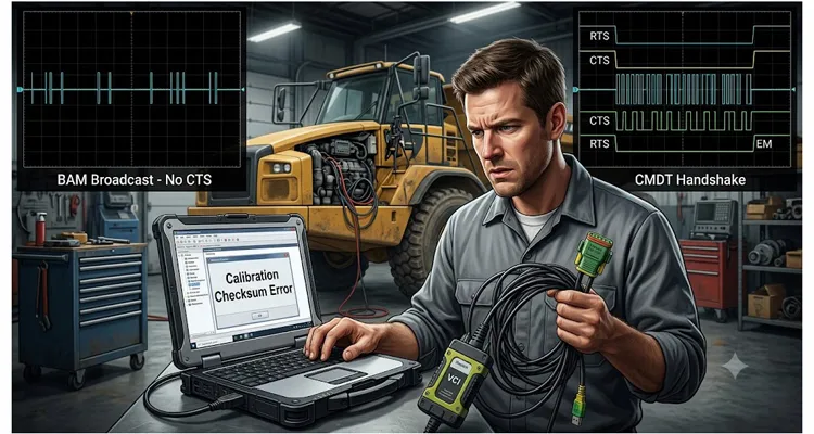
I want to walk you through a failure that cost us three days on a dyno cell in Toledo. The vehicle was a Tier 4 final off-highway machine—19-liter, inline-six, dual ECUs sharing a single CAN bus backbone. The symptom reported by the field service laptop was straightforward: “Calibration checksum invalid.” The ECU would reject the reflash halfway through block 4 of 7, every single time. Predictably, the first reflex was to suspect the calibration file sitting on the engineering server had become corrupted. They re-exported the .hex from the calibration tool. Same error. They blamed the memory sector on the ECM. They swapped the controller. Same error.
It wasn’t the calibration. It never was.
The root cause sat one layer below: a mismatch in how the bootloader negotiated multi-packet transport. One tool was sending BAM. The ECU’s bootloader was sitting there waiting for a CMDT connection. The transport layer was silently throwing away data packets, and the application layer—the flash routine—was interpreting the incomplete data stream as a corrupt block. That’s the kind of bug that makes you question every assumption you’ve made since the schematic review.
This article isn’t a tutorial on the J1939 transport layer. The SAE J1939-21 document already exists, and if you haven’t read it, stop reading this and go read that first. For context on how the standard fits together, the SAE J1939 Wikipedia page is a helpful starting point. What I’m going to share here are the specific, painful ways that BAM and CMDT mismatches manifest in real embedded systems, why they mimic calibration and memory faults so convincingly, and what you can do about it when your Vector log says one thing and your ECU says another.
The Scene Where This Usually Bites You
You almost never see this BAM versus CMDT problem when you’re on a bench with one ECU and the OEM’s own service tool. That path has been tested to death. It rears its head in three specific scenarios, and if you work with heavy-duty vehicles or industrial equipment, you’ve probably hit at least one of them.
Mixed-Supplier Systems
You have an engine ECM from Supplier A, an aftertreatment controller from Supplier B, and a telematics gateway from a third vendor who bid low on the harness contract. Supplier A’s bootloader expects CMDT because they need the handshake and flow control for precise flash programming. The telematics gateway—whose firmware was written by someone who interpreted the J1939 standard a little too loosely—broadcasts calibration data over BAM because the gateway’s only job is to push large parameter sets downstream, and BAM is simpler to implement. But that simplicity in the gateway translates into unseen reliability risks for the whole CAN bus. When the gateway starts shoving data at the engine ECM without establishing a connection, the ECM’s transport layer buffer overflows. The ECM doesn’t log a transport protocol error. It logs a NVM integrity fault, because that’s the module that detected the garbage. Your diagnostic trouble code points straight to the EEPROM bank. The diagnostic signpost was pointing east while the problem was west.
Fleet Management Interfaces
I’ve seen this exact architecture on refuse trucks and city buses: a third-party telematics unit tied into the public CAN network. The fleet manager wants to pull performance maps, histogram data, or entire calibrations over the air. The telematics unit uses BAM—because the integrator assumed “broadcast means everyone can see it, simpler is better.” Meanwhile, the chassis controller needs to flash a steering angle sensor calibration at the same time. Two BAM sessions collide on the bus, sequence numbers get interleaved, and the receiving nodes see corrupt multi-packet messages. The cluster turned into a U-code waterfall, with SPNs blinking faster than the operator could note them. The technician at the depot replaces the instrument cluster. It doesn’t help.
Prototype and End-of-Line Test Benches
I’ve walked into test cells where a custom in-house calibration tool built on a PCAN or Kvaser interface was the source of the whole mess. The Python script that sends the calibration package was written two summers ago by an intern who’s long since graduated. It uses BAM because it was copied from an example project that was intended for broadcast parameter distribution to multiple displays on an agricultural implement. Now you’re trying to flash an ECU that strictly expects CMDT—its bootloader refuses to accept anything but a CMDT handshake. The tool sends the entire transfer without waiting for a Clear to Send. The ECU buffers what it can, times out on the missing handshake, and reports “download rejected.” The test bench operator logs it as an ECU defect. The ECU goes back to the supplier for root cause analysis. The supplier returned it with a one-line summary: “Tested OK on our bench.” Twelve-hundred dollars in shipping and two weeks of downtime for a protocol configuration issue.
What’s Actually Happening on the Bus: BAM versus CMDT
You already know the basics. But in my experience, the nuances are where the bugs hide. Let me lay this out the way I wish someone had explained it to me ten years ago. For a detailed walkthrough of the transport layer mechanics, CSS Electronics’ J1939 explained tutorial is an excellent companion read.
I keep a printout of a trace I captured on a 2018 mixer truck. PGN 60416 hit the bus with a control byte of 0x20 and a destination address of 0xFF—classic BAM. The sender was a telematics gateway pushing an eleven-hundred-byte parameter block. It blasted the data packets with exactly fifty-two milliseconds between them, right at the edge of the spec. No handshake. No receiver asking for a re-send. The engine ECM, which had its CMDT-only bootloader active, treated the incoming bytes the way a spam filter treats unsolicited attachments. That printout is still taped to my monitor because it explains the whole problem in six seconds of bus traffic.
On the other side of the fence, CMDT couldn’t be more different. I once sat across from a supplier’s engineer while we manually decoded a trace on a bench. The service tool sent PGN 60416 with Control Byte 0x10—Request to Send (RTS)—to address 0x03. The ECM responded with Control Byte 0x11, Clear to Send (CTS), granting exactly 13 packets starting from sequence number one. The tool fired those 13 frames, then waited. The ECM sent another CTS for the next block, and the dance repeated until the entire three-thousand-byte flash kernel had crossed the wire. The last frame was Control Byte 0x13, End of Message Acknowledgment. That trace made it obvious: in CMDT the receiver owns the pace. It can say “slow down,” “resend packet 17,” or “abort.” BAM has none of that. The sender just assumes the receiver will catch every single frame, perfectly, at the speed it chooses.
At the heart of every misdiagnosis lies one simple fact: BAM trusts the sender to pace the transfer; CMDT trusts the receiver. That single difference in ownership of flow control is what turns a perfectly good binary file into a reported calibration checksum fault. Here’s how the two protocols stack up side by side:
| Feature | BAM (Broadcast Announce Message) | CMDT (Connection Mode Data Transfer) |
| Addressing | Global (0xFF) – no destination address | Specific node address (e.g., 0x03) |
| Session Initiation | Control Byte 0x20, announces total size and packet count | Control Byte 0x10 (RTS), specifies PGN, size, packets per block |
| Flow Control | Sender-driven; 50 ms minimum spacing between packets | Receiver-driven; CTS grants blocks of packets |
| Handshake | None | RTS → CTS → Data Block → End of Message Acknowledgment (0x13) |
| Error Recovery | No retransmission mechanism | Receiver can request specific packet re-send, abort possible |
| Typical Use Cases | Multi-display parameter broadcast, simple telematics pushes | One-to-one ECU flash programming, calibration uploads/downloads |
When a BAM sender tries to talk to a CMDT listener, the receiver never sees an RTS within its initialization window. It never issues a CTS. Data packets arrive unannounced, get dumped into a buffer that the application layer hasn’t allocated because no connection was established, and eventually—depending on the stack implementation—either fill up and overflow or get discarded as unrecognized multi-packet sequences. The receiver’s diagnostic routines see an incomplete or corrupted data block and log a fault. Because the data was intended for a memory region associated with calibrations, the fault code inevitably mentions calibration checksum, NVM integrity, or flash verification failure.
Flip the mismatch around and the result is equally silent. A CMDT sender transmits an RTS to a specific address. A BAM-configured receiver isn’t listening for connection requests; it’s waiting for a BAM announcement on the global address. The RTS goes unanswered. The CMDT sender retries a few times and then gives up, logging a timeout. The application interprets the timeout as a communication loss with the source module. Neither side reports a transport protocol configuration error, because each side believes it’s operating correctly per its own configuration.
The J1939 standard doesn’t dictate which transport protocol a given PGN must use for calibration downloads. That decision is made by the system integrator, the ECU supplier, and the service tool developer. When any one of those three makes an assumption, you get the kind of mismatches I’m describing.
Why It Looks Exactly Like a Calibration Fault
This is the part that frustrates engineers the most. You’d expect a transport protocol mismatch to throw a clear error code. In practice, it rarely does. Here’s why the ECU reports a calibration problem instead.
The Application Layer’s Blind Spot
During a multi-packet data transfer that fails partway through, the receiver has already begun writing the bytes it has to its allocated flash region. The application layer—the flash bootloader—has no window into the transport layer’s conversation. All it can do is run a CRC-32 over whatever landed in memory, compare it to the expected checksum sent in the final packet, and if it doesn’t match, report “Checksum Error—Operation Aborted.” It never knows that the transport session was the problem.
Down in the transport layer, the CAN stack stays silent—many implementations deliberately discard unrecognized frames to keep the error logs clean on a noisy bus. A BAM data packet arriving at a CMDT listener looks exactly like noise to a stack that isn’t keeping a global receive buffer open.
How Memory Corruption Adds Confusion
Another layer of confusion comes from temporary memory corruption. Some controllers use a dual-bank flash architecture where the incoming calibration is written to an inactive bank and then validated before switching banks. If the data stream is corrupted due to missing packets, the validation routine runs on half-written memory. The hardware memory protection unit may flag a fault that gets logged as an ECC (Error Correction Code) error or a flash controller exception. The technician sees a hardware-level memory fault and naturally suspects the physical memory IC. I’ve seen perfectly good ECMs scrapped because of this. When you multiply that phantom fault across a fleet, the costs become staggering—we broke down the numbers in network calibration faults and their phantom cost to a fleet.
How to Identify This in the Wild
Before you tear down a machine or send an ECU back to the supplier, do this. For a repeatable process you can hand to a technician, we’ve turned these identification steps into a structured J1939 diagnostic workflow that cuts diagnostic time.
Step 1: Pull a Full CAN Trace with Microsecond Resolution
- Use a Vector VN1630 or Kvaser Memorator interface—any tool that doesn’t drop frames will work.
- Capture raw bus traffic, not the interpreted signals from a service tool display; the factory diagnostic tool may mask the exact protocol exchange.
- Capturing the trace is the first step; knowing what a clean BAM versus CMDT session looks like on screen is the next. We cover that visual distinction in detail in reading J1939 waveforms like a pro.
- I once connected a VN1630 to a bus retrofit and saw four BAM announcements from the telematics unit in the first two seconds after ignition-on, with no CTS from the engine ECU. That was the moment the light bulb went on—the entire calibration rejection sequence was a transport protocol mismatch, not a memory defect.
Step 2: Filter for PGN 60416 (0xEC00) – Transport Protocol Connection Management
- Examine the Control Byte in byte 1 of the data field.
- Control Byte 32 (0x20) with destination address 0xFF indicates BAM.
- Control Byte 16 (0x10) followed by Control Byte 17 (0x11) indicates a CMDT handshake.
- I’ve narrowed a three-day search to thirty seconds by filtering on just those two control bytes.
I’ve narrowed a three-day search to thirty seconds by filtering on just those two control bytes.
- Look for BAM announcement frames without any CTS response from the intended receiver.
- If data packets (PGN 60160, Transport Protocol Data Transfer) flood the bus, then stop, then a new BAM announcement appears, the receiver likely expects CMDT but is being addressed by a BAM sender.
Step 4: Check for Unanswered RTS Frames
- If RTS messages target a specific node address and that node never replies with CTS or Abort, the receiving node either isn’t configured for CMDT, is off-bus, or has a wrong address.
- If the node is alive and transmitting other messages, the mismatch is in the transport layer configuration.
Step 5: Compare Bootloader Documentation with Service Tool Configuration
- In many integration projects, the line item “supported transport protocol for flash download” is buried on page 84 of a 300-page manual.
- Ask the ECU supplier directly: “Does the bootloader for flash programming require CMDT, or will it accept BAM?”
- If the answer is CMDT-only, ensure every tool sending large data payloads to that ECU is set to CMDT.
- Once you’ve worked through these five steps, you’ll have your answer. We’ve summarized the entire logic into a one-page J1939 calibration fault troubleshooting flowchart you can print and keep on the bench.
The Step-by-Step Fix (Done Right)
Step 1: Isolate Data Path Transport Protocols
- Map every node on the backbone and every PGN larger than 8 bytes.
- Calibration uploads/downloads typically use memory access messages (PGN 57088–57119 for DM3-type operations; verify with your OEM).
- Parameter distribution to multiple displays usually uses BAM.
- One-to-one programming and configuration sessions use CMDT.
- Document this in a system communication matrix.
Step 2: Align the Service Tool Configuration
- Most PC-based service tools with a pass-through interface (SAE J2534 or RP1210) use a configuration file (XML or registry setting).
- Look for a parameter named “MultiPacketMode” or “TxProtocol” with values 0 for BAM, 1 for CMDT.
- Set it to match the ECU’s bootloader requirement—no software rebuild needed.
Step 3: Implement Dual-Mode Receive on the ECU Side (If You Write the Bootloader)
- A well-designed transport layer can listen for BAM on the global address and accept CMDT connections on its specific address simultaneously.
- Register expected PGNs by transport mode at the application layer.
- The memory footprint for a dual-mode handler is typically under four kilobytes of ROM—a small cost for field robustness.
Step 4: Intentionally Test the Mismatched Scenario
- Configure the tool to use BAM when the ECU expects CMDT, and vice versa.
- Verify that the ECU logs a clear fault like “Transport Protocol Mismatch” instead of a generic NVM checksum error.
- If it doesn’t, file a firmware change request. Diagnostic coverage matters.
Step 5: Time-Slice BAM Sessions in Fleet Systems
- J1939 allows only one BAM session on the network at a time; two simultaneous BAM transfers will corrupt each other.
- Implement a session manager on the telematics unit that queues BAM transfers sequentially and waits for completion before starting the next.
Five Mistakes I See Repeatedly
Mistake 1: Assuming All J1939 Devices Support CMDT
I’ve lost count of how many times an engineer took it for granted that every J1939 node speaks CMDT. Simple displays, I/O expanders, and even some aftertreatment controllers handle multi-packet receive only through BAM. CMDT needs a heavier stack with connection state management and more RAM. Always check the device’s conformance statement or ask the supplier directly.
Mistake 2: Changing the ECU Address Without Updating the Service Tool Routing Table
In CMDT, the RTS is addressed to a specific node. If the ECU moves from address 0x03 to 0x0B, every service tool that flashes that ECU must know the new address. Otherwise, RTS frames go to a dead address, the session times out, and the flash routine never starts.
Mistake 3: Ignoring the 50-Millisecond Minimum Interval in BAM
The 50-ms timer isn’t a suggestion—it’s baked into the BAM spec to prevent buffer overruns. I’ve seen PC-based tools on non-real-time operating systems spit packets at 30 ms when the Windows scheduler feels generous, and the ECU’s receive buffer chokes intermittently. The symptom is intermittent checksum errors that look like a hardware defect but are actually a timing violation.
Mistake 4: Using a Single CAN Channel Without a Gateway
Bench-flashing an ECU directly on its pins is a closed network. In a vehicle, the same ECU shares a bus with sixteen other nodes. The BAM broadcast hits every node, some of which may have active transport sessions. Account for bus loading and other large-packet traffic, or gate transmissions through a gateway that manages session timing.
Mistake 5: Conflating the Transport Protocol Error with the Application-Layer Fault
I see this constantly: the error report says “NVM checksum failure,” and someone immediately orders a replacement ECU. Nobody runs a ten-minute CAN trace to see whether the transport layer conversation even completed. Always look at the transport layer first when a calibration transfer fails. It’s free, it’s fast, and it rules out the most common invisible culprit.
How to Know the Fix Actually Took
After you’ve aligned the J1939 transport protocol settings, here’s how I validate that the BAM/CMDT mismatch is truly resolved.
Validation Test Sequence
- Transfer the same calibration file ten times in a row without a single checksum error or timeout.
- Vary the interval between transfers: immediate, then five minutes apart.
- Run the transfer cold (ECU powered up from ambient) and hot (engine at full load for an hour, ECU housing above seventy degrees Celsius).
- Increase bus load by transmitting high-frequency PGNs from other nodes during the transfer.
Interpreting the CAN Trace and ECU Logs
- The trace should show a clean session opening, all data packets in order, and a clean close.
- For CMDT, expect RTS, CTS, data block, and End of Message Acknowledgment with no retries and no aborts. Transfer time should be consistent.
- ECU diagnostic memory must contain zero new NVM integrity faults, ECC errors, or flash controller exceptions.
- If the ECU supports a transfer success counter, it should increment exactly once per successful transfer.
- If a calibration version or checksum register is queryable, read it after each transfer and verify it matches the sent file.
Tools and Cabling That Won’t Lie to You
During the investigations I described, the single most important physical component was the cable between the interface hardware and the vehicle diagnostic connector. We’ve spent an unreasonable amount of time chasing protocol-level ghosts that turned out to be an intermittent pin in a worn-out Deutsch connector or a cable with inconsistent termination impedance causing reflections on the CAN bus. When you’re capturing CAN traces to diagnose transport protocol behavior, the integrity of the physical layer has to be beyond reproach.
Why Your Diagnostic Cable Is an Instrument, Not a Variable
When you’re trying to decide whether a missing CTS is a protocol issue or a corroded pin in the Deutsch connector, the cable has to be an instrument, not a variable. That’s why the J1939 cables we use—and build for OEMs—go through a check that includes a resistance sweep of the 120 Ω terminator while the connector is heated to eighty degrees. I’ve seen a terminator drift by four ohms when warm, enough to skew the recessive-level voltage just enough to cause sporadic frame errors that look like transport-layer timeouts. That’s why we validate every cable against the same thermal drift documented in J1939 termination resistance drift: hot vs. cold. Our assembly cell works to IATF 16949 process controls, which means that every termination resistor is measured at operating temperature, not just on a cold bench. And before a cable leaves the floor, it undergoes a four-step inspection:
- Continuity on every pin
- Visual check of each crimp and solder joint
- Load test on the terminator at temperature
- Final plug-and-function test on a live CAN network
A cable that passes 100% electrical testing but has a poorly molded strain relief will fail in the field after a few dozen plug cycles. We’ve seen it, and we’ve fixed it. In the same way a 23-cent terminator can trigger catastrophic fleet downtime, a marginal cable introduces variables you can’t afford.
Custom OEM Diagnostic Cables Without Minimum Order Headaches
Our factory—running under ISO 9001, IATF 16949, and ISO 14001 certifications—builds these cables as OEM products for several equipment manufacturers. We customize cable lengths from one foot to fifty feet, jacket materials for in-cab versus engine-bay environments, connector colors to match corporate branding, and wire gauge for specific installation requirements. The design files stay with you. Nobody else gets your custom pinout or your specific overmold compound. If your engineering team needs a diagnostic harness that integrates a CAN termination switch, a backlit connector, or a specific labeling scheme, we do that without minimum order quantity headaches. It’s a direct engineering conversation, not a catalog order.
If you’re in the middle of a transport protocol problem and you suspect your physical layer might be contributing, reach out with your specific electrical requirements. My colleague Linda handles the technical sales conversations, and she’s been deep enough in CAN diagnostics to understand the difference between an idle bus and a bus stuck dominant. You can connect with her directly via WhatsApp (https://api.whatsapp.com/send/?phone=8617307168662&text=Need+Help%3F+Chat+linda+WhatsAPP&type=phone_number&app_absent=0) for a conversation about your project’s cabling and connector needs, or use our contact form (https://obd-cable.com/contact/) to send over drawings, pinouts, or questions for an engineering quote.
FAQ
Can an ECU support both BAM and CMDT on the same J1939 address?
Yes. The transport layer can maintain a BAM receive buffer on the global address and a separate CMDT connection handler on its specific address simultaneously. The key is that the PGNs expected via each mode must be pre-registered so the stack routes incoming data to the correct handler. This is standard practice in many modern ECUs.
Why do some implementers prefer BAM for calibration distribution if CMDT is safer?
Because BAM requires less code and less RAM. There’s no connection state machine, no timeout handling, no retry logic. For a telematics unit that pushes parameter sets to multiple identical controllers on an implement bus, BAM is a simpler design choice. The tradeoff is the lack of flow control, which becomes a problem at high bus utilization.
What’s the most common diagnostic trouble code that a BAM/CMDT mismatch produces?
I see SPN 630 (Calibration Memory Erratic) and SPN 628 (Program Memory Erratic) most often. The exact SPN varies by OEM, but the pattern is always the same—the fault references a memory integrity check, never a communication timeout.
Does the J1939 standard mandate which transport protocol to use for flash programming?
No. SAE J1939-21 defines both mechanisms but leaves the selection to the application profile. Some OEMs publish a networking specification that mandates CMDT for all reprogramming sessions. Others don’t. Always check the vehicle manufacturer’s networking specification, not just the SAE standard.
Can a CMDT transfer time out during slow flash write operations on the ECU?
Yes, and this can be misinterpreted as a protocol mismatch. The receiver sends CTS and expects data packets within a specific time window. If the ECU’s flash write routine stalls the CAN controller for longer than the CTS timeout, the sender will abort. The fix is to align the CTS timeout value with the worst-case flash write time, not to switch transport protocols.
How does the J1939 transport layer interact with J2534 pass-through devices?
The J2534 API abstracts the transport protocol into a software library on the PC. The pass-through device firmware handles the CAN frames. A mismatch can occur if the PC software selects BAM and the device’s firmware implements the protocol differently than the ECU expects, or if the software’s configuration file overrides the device’s default. Always check both the tool configuration and the pass-through device’s conformance statement.
What bus load percentage starts to cause problems for BAM transfers?
In my experience, above 60% sustained bus load with multiple high-priority PGNs, BAM starts to lose packets because the sender’s 50-millisecond spacing isn’t always sufficient headroom when arbitration delays stack up. At 80% and above, I’ve seen consistent BAM transfer failures. CMDT handles high bus loads better because the receiver can pace the flow based on actual buffer availability.
If a device claims to be J1939 compliant, does it automatically support both BAM and CMDT?
No. I’ve seen a device that was perfectly compliant with J1939-21’s mandatory clauses because it only sent single-frame messages. It didn’t need a transport layer at all. The moment the system integrator tried to push a calibration file to it—a file that required segmentation—the whole transfer silently failed, and the ECU downstream logged a memory error. Compliance doesn’t guarantee multi-packet capability.
Can a protocol analyzer distinguish a BAM/CMDT mismatch from a genuine memory fault?
The protocol analyzer can only tell you what happened on the bus. If you see BAM data packets flowing to a node that never acknowledges them, and the node later reports a memory fault, the analyzer gives you the circumstantial evidence to connect the two. The definitive diagnosis still requires human interpretation of that CAN trace.
What should I ask an ECU supplier about transport protocol support before integrating?
Ask these three questions: “Does the bootloader for flash reprogramming require CMDT exclusively, or does it also accept BAM?” “What is the CTS timeout value, and is it configurable?” “Does the diagnostic event log record a unique fault for transport protocol mismatches, or will it report a generic memory checksum error?” Get the answers in writing.
The next time a calibration file fails to flash, and your screen says checksum error, don’t trust the screen. Pull the CAN trace. Look at the transport layer session. The odds are better than even that the bits are fine—they’re just arriving through the wrong conversation protocol. Fix the handshake, and the error that looked like a dead memory chip disappears into thin air.
