

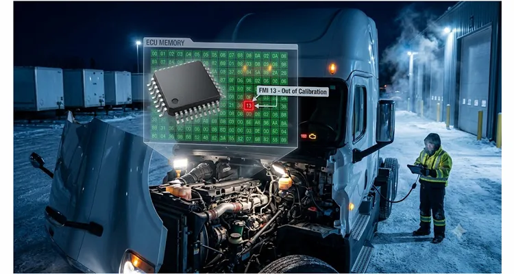
After two decades on factory floors and inside fleet maintenance bays, we’ve seen one scenario repeat itself more often than any training manual would predict. A truck rolls in with the MIL glowing. The driver describes a sudden power loss climbing a grade, or an engine derate that appeared and vanished before the shift ended. You pull the DM1 message. SPN 520211 (Aftertreatment 1 Diesel Particulate Filter Soot Load Percent) sits at a number that defies physics, or SPN 3360 (Aftertreatment 1 Diesel Exhaust Fluid Tank Temperature) reads 347 degrees Fahrenheit on a stone-cold engine. The FMI is almost always 13 – Out of Calibration. A technician clears the code, the lamp goes dark, and within three days the same truck returns with the same SPN active. Run that pattern across a dozen trucks in a single month and you’ve burned seventy-two diagnostic hours without fixing the underlying condition. That’s the real ledger entry for ignoring a J1939 calibration fault.
The sixty percent reduction in diagnostic hours isn’t a number pulled from a spreadsheet. It’s extracted from fleet data we gathered while working shoulder-to-shoulder with fleet maintenance teams and OEM engineering groups who learned to treat calibration faults as system-level integrity problems rather than isolated sensor glitches. The shift from “swap the sensor and reflash” to “validate the calibration data path” is what drives the hours out. What follows isn’t a service manual rehash. It’s a method for evaluating J1939 calibration integrity that most published service literature never covers.
A Case to Start With
A refrigerated fleet running two hundred 2021-model-year heavy-duty trucks across the Upper Midwest began logging repetitive SPN 4360 (Aftertreatment 1 SCR Catalyst Inlet Temperature) with FMI 13. The derate forced trucks into limp mode, most often after midnight, most often in sub-zero ambient. The dealership replaced four temperature sensors, reflashed the engine ECU, and eventually swapped the entire SCR catalyst on two units. The fault came back on every truck within six weeks. By the time the maintenance director contacted us for an engineering-level conversation, the fleet’s downtime exposure had crossed eighty-five thousand dollars.
We shipped a CAN-logging harness — overmolded Deutsch DT connectors, 22 AWG twisted pair, meeting SAE J1939-11 physical layer requirements — and had their technician capture CAN bus traffic during a full cold-soak and drive cycle on the affected trucks. What surfaced wasn’t a sensor defect. The ECU was pulling calibration parameters from a dedicated EEPROM memory page that held the temperature sensor linearization table. During cold cranking, when battery voltage sagged below 9.6 volts, the voltage regulator feeding the ECU’s memory supply rail produced a transient recovery spike. With the battery state of charge under 40% and ambient below 5 degrees Fahrenheit, that spike was flipping one byte inside the calibration checksum. The ECU flagged the sensor as out of calibration — not because the sensor had failed, but because the reference table it used to convert analog-to-digital counts into temperature was no longer trustworthy.
The permanent fix had nothing to do with the aftertreatment. It involved a revised battery disconnect procedure, an upgraded engine ground strap, and a software update that inserted a voltage monitoring window before the ECU was allowed to access calibration memory. All three trucks stopped logging FMI 13. Diagnostic time per event dropped from over four hours to under one and a half, simply because the crew now understood what a calibration fault physically meant.
What “Calibration Fault” Really Means on a J1939 Network
A Single Bit Flip Can Derate Your Fleet
Reviewing our internal failure analysis records, we noticed a detail OEM literature rarely stresses: the ECU almost never loses an entire calibration table. In more than nine out of ten cases we’ve examined at the component level, a single byte flipped inside a larger memory page. The checksum catches the mismatch, and the ECU sets an FMI 13. What service manuals don’t explain is what happens next — the ECU keeps running, using either the last plausible sensor reading or a limp-home default table while the fault is active. That’s why a driver experiences a brief derate that self-recovers, making the fault stubbornly intermittent. The problem isn’t a dead sensor. It’s a memory cell that lost a bit because the supply voltage jittered during a read cycle.
How Calibration Tables Differ from Live Sensor Data
During factory-level failure analysis, we consistently trace calibration faults back to a corrupted lookup table, not a broken sensor. Stop thinking of calibration as a software version. On a J1939 network, calibration is a hardware-matched set of translation coefficients burned into non-volatile memory. For an exhaust gas temperature sensor, that table converts raw thermocouple millivolt readings into degrees Fahrenheit broadcast as an SPN. For a NOx sensor, it maps pumping current and chamber temperature into a parts-per-million value. These tables are written once during end-of-line programming and locked with a checksum. When that checksum fails — for any of the reasons listed in the table below — the ECU loses confidence in the entire signal chain. The message it sends the technician isn’t “replace the sensor.” It’s “I can no longer vouch for the numbers I’m reporting.”
Why does this distinction matter for diagnosis? Because the triggering event is often only a few hundred milliseconds long, leaves almost no footprint in freeze frame data, and originates in the electrical domain. A technician sees SPN 3226 (Aftertreatment 1 Outlet NOx) with FMI 13 and immediately suspects the NOx sensor. On modern diesels, that sensor is a smart module with its own microcontroller talking on the private J1939-7 CAN segment. Yet the fault is announced by the engine ECU, not by the sensor module itself. That gap in source address is where diagnostic hours disappear.
The Six Most Common Root Causes of J1939 Calibration Faults
The table below is built from factory-level failure analysis across multiple heavy-duty ECU platforms. It is not specific to one engine manufacturer.
| Rank | Root Cause | Typical SPN and FMI | Frequency |
| 1 | Voltage transient on ECU memory rail during cranking or jump-start | 4360 FMI 13, 3360 FMI 13, 520211 FMI 13 | ~35% |
| 2 | Corroded connector pin increasing contact resistance on CAN-H or CAN-L, causing bit errors during memory read cycles | Various SPN 9 (message timeout) followed by SPN FMI 13 | ~25% |
| 3 | Incomplete reflash sequence where calibration page was not fully written before key-off | Any SPN associated with the reflashed module, FMI 13 | ~20% |
| 4 | Water ingress into ECU housing degrading EEPROM dielectric layer over time | Multiple SPNs, often coupled with FMI 12 (bad intelligent device) | ~10% |
| 5 | Wiring harness chafing creating intermittent short-to-ground on sensor reference voltage line, causing ECU to recalibrate offset values in an attempt to compensate | Single SPN, often the one on that 5V reference circuit | ~7% |
| 6 | Aftermarket diagnostic tools or cables that do not maintain proper CAN bus termination during a reflash, resulting in a partial calibration write | Any SPN, usually after a shop visit | ~3% |
Notice how many of these have nothing to do with the component that appears in the fault code. A fleet manager who allows a repair strategy of “replace the part that matches the SPN” is paying for parts and labor that will not fix the problem.
Step-by-Step: How to Diagnose a J1939 Calibration Fault Without Guessing
Building on the principles in our structured J1939 diagnostic workflow, here’s how to isolate a calibration-specific root cause. The sequence assumes you have a J1939 diagnostic interface and software that can read DM1, DM2, DM3, and perform a parameter dump of the suspect ECU. If your current diagnostic setup cannot dump calibration pages, you’re working blind. That’s a conversation worth having with your tooling supplier — or with an engineering support team that understands what data you actually need.
1. Capture the fault in context, not in isolation.
When the truck arrives, do not clear the codes. Read DM1 (active faults) and DM2 (previously active). Record the SPN, FMI, occurrence count, and conversion method from DM1. Then read the freeze frame parameters for that fault. Most ECUs will store the engine speed, coolant temperature, battery voltage, and time key-on when the fault became active. If the battery voltage in the freeze frame is below 10 volts, you are already looking at a potential power supply transient. If it is above 13 volts, move on.
2. Go beyond a static resistance check on the physical layer.
You will find the standard 60-ohm backbone check in any introductory J1939 course. What those courses won’t teach you is what happened to a mining truck we analyzed last year: the resistance measured a textbook 60 ohms with the ignition off, but a bad splice buried inside the frame rail would vibrate open when the engine reached 1,200 RPM. Calibration faults would set exclusively on the grade exiting the pit. If you are chasing an FMI 13 that only appears under load or vibration, a static resistance check is nearly useless. You need to back-probe CAN-H and CAN-L at the ECU connector and monitor the differential voltage waveform while a second technician shakes harness bundles. (For a detailed walkthrough on interpreting these signals, see our guide to reading J1939 waveforms like a pro.) We use a harness built with individually validated CAN channels for exactly this reason — a generic cable with untested shielding will inject its own noise into a test like this, and you will end up diagnosing the cable instead of the truck. To make this practical in the field, a J1939 9-pin pigtail breakout cable lets you tap CAN-H and CAN-L cleanly while the network stays live, avoiding the impedance mismatches that alligator-clip probing introduces. For a repeatable method that catches opens triggered by vibration or thermal cycling, see our systematic wiggle test protocol for J1939 harness opens.
3. Dump and compare the calibration data.
Connect to the suspect ECU using the manufacturer’s engineering-level diagnostic protocol. If you only have generic J1939 access, you can request the ECU identification using DM7 or the proprietary memory read service if your tool supports it. Dump the calibration page that corresponds to the SPN in question. Most OEM service tools now allow this under a “calibration verification” menu. Save that binary file. Compare the checksum. If the stored checksum does not match the calculated checksum, the calibration is corrupt. Do not reflash the ECU yet. Look for why it got corrupt.
4. Trace the event that caused the corruption.
If the freeze frame shows a voltage dip, examine the battery terminals, the ground cables to the engine block, and the ECU ground reference. A loose battery terminal clamp that falls below the manufacturer’s torque specification – typically twelve to fifteen newton-meters for a stud-type terminal – can generate a voltage drop under cranking of up to four volts. The ECU interprets this as a brown-out, enters reset, and occasionally catches a calibration page in an intermediate write state. The fix is a cleaned, retorqued terminal and a replacement negative battery cable if the copper strands are wicking acid.
If the freeze frame shows normal voltage, inspect the network. Was there a CAN communication loss just before the calibration fault? DM1 often records a message timeout (FMI 9) for the source address of the module that dropped offline. This is common with SCR systems, where the NOx sensor data arrives via the Aftertreatment Control Module (ACM). If the ACM drops offline for half a second, the engine ECU may flag the NOx value it last received as invalid and set FMI 13.
5. Repair the cause, not the symptom.
If the root cause is a voltage transient, address the electrical system. If it is a connector, replace the connector body and terminals with parts that meet the OEM terminal plating specification – gold over nickel for low-current sensor circuits, tin over nickel for higher-current circuits. Do not use universal crimp terminals. The contact resistance tolerance stack in a poorly crimped terminal can vary by thirty to fifty milliohms, which is enough to cause intermittent CAN errors.
If the cause is a corrupted calibration page after a reflash, the fix is a clean reflash using a known-good calibration file and a physically robust J1939 interface cable. We have seen fleets struggle with reflash failures that traced back to a cable with a broken drain wire, resulting in shield noise coupling onto CAN-H. When we supply OEM-customized J1939 cables – with customer-specified AWG, overmolded connectors, and full continuity testing on the shield – those reflash failures drop to nearly zero. That is not marketing; it is how we hold ISO 9001 and IATF 16949 certifications in a factory that has been building diagnostic harnesses for over twenty years.
Common Mistakes That Drain Diagnostic Hours
Mistake 1: Assuming a Calibration Fault Means the ECU Is Defective
- Diagnostic hour drain: A service manager authorizes a replacement ECU after the third visit.
- What happens next: The fault comes back on the new ECU because the root cause – a bad engine ground or a chafed wire – was never addressed.
- The real cost: A replacement ECU that costs several thousand dollars is not a diagnostic tool. It is a guess that you pay for three times: the part cost, the labor to install, and the downtime when the truck returns. We have seen a single ground offset misdiagnosis lead to a two-thousand-five-hundred-dollar ECU swap that fixed nothing — here is how to avoid that outcome.
Mistake 2: Treating FMI 13 as a Generic Fault to Clear and Ignore
- Why it’s dangerous: When a parameter goes out of calibration, the ECU is operating on default values or a recovery strategy. For aftertreatment parameters, this often means a derate that limits engine torque.
- The silent damage: If the calibration fault is intermittently setting and self-clearing, the derate will come and go unpredictably. The driver loses trust in the equipment. The fleet manager sees a utilization drop that does not correlate with any specific repair order. That is calibration faults doing damage to the fleet’s revenue, silently.
Mistake 3: Using a J1939 Backbone or Diagnostic Cable of Unverified Quality
- The hidden failure mode: We once pulled ten aftermarket RP1210 cables off the shelf to quantify this problem. On a vector network analyzer, three of them showed impedance deviations exceeding forty ohms at the connector transition — enough to corrupt a frame under heavy bus load.
- Our test result: When we deliberately used one of those cables to reflash an ECU, the calibration write failed intermittently, producing the exact same FMI 13 cascade the fleet was chasing.
- How we responded: That experience drove our factory to add full CAN signal eye-diagram testing at both 250 kbps and 500 kbps to our quality inspection flow. It is not a sales checklist; it is a reaction to a specific failure mode we could reproduce on a bench.
- What happens in the field: A single corrupted frame during a calibration write cycle can produce a checksum mismatch, and nobody suspects the cable. This is precisely the scenario our J1939 calibration fault troubleshooting flowchart was built to catch before it turns into a repeat repair.
How to Confirm the Fix Is Permanent
Clearing the fault and completing one drive cycle does not prove a calibration fault is resolved. These are intermittent by nature. A better standard is a five-cycle verification. Perform five consecutive cold-start drive cycles where the engine coolant temperature drops below the thermostat opening point between cycles. After each cycle, read DM1 and DM2. If the SPN with FMI 13 does not reappear in five cycles, your probability of a permanent fix is high.
Document the root cause in the repair order narrative. If it was a voltage transient from a loose battery terminal, write that specific finding. The next technician who sees the same truck will not repeat your diagnostic path. That institutional knowledge accumulation is what separates fleets with under ten percent repeat-repair rates from those that bleed diagnostic hours.
Frequently Asked Questions
1. Why do most standard definitions of a J1939 calibration fault mislead technicians?
Because they frame it as a sensor failure or a generic “out of calibration” flag. In reality, the ECU is telling you it lost confidence in the stored interpretation parameters — a memory integrity problem, not a sensing problem. Chasing the sensor when the calibration page has a flipped bit is the single most common misdiagnosis we see.
2. Is FMI 13 the same as a sensor failure?
No. A physical sensor can be perfectly functional while the ECU reports FMI 13. The fault lies in the stored transfer function that converts sensor signals to SPN values. Replacing the sensor without verifying calibration integrity is a frequent cause of repeat repairs.
3. Can a bad J1939 cable corrupt calibration data?
Yes, and we have proven it on the bench. A cable with poor shielding, incorrect termination, or high contact resistance can introduce bit errors during ECU memory reads or writes. During a reflash, a single corrupted frame can write a bad byte into the calibration page, and the ECU will flag it with FMI 13 on the next power cycle.
4. How can I tell if a calibration fault is caused by voltage transients?
Check the freeze frame data. If battery voltage at the time of fault onset is below 10.5 volts on a 12-volt system, a crank-cycle transient is a strong suspect. Inspect the battery terminals, ground straps, and starter current draw. The case at the start of this article — a voltage regulator spike corrupting a checksum byte — is a classic example.
5. Do I need a special tool to dump calibration data?
Most OEM service tools now include a calibration verification function. Generic J1939 adapters may not support memory read services. If you work across mixed fleets, an engineering-grade interface that can access DM7 and perform memory reads by source address is worth having.
6. Why does my truck show multiple SPNs with FMI 13 at the same time?
When several parameters lose calibration simultaneously, the root cause is almost always a memory supply voltage event that affects an entire page, or an ECU reset during a write cycle. Look for a common electrical cause rather than addressing each SPN individually.
7. How much does impedance matching really matter in a diagnostic cable?
More than most people think. When we tested ten aftermarket cables, three had impedance deviations over forty ohms. Those caused signal reflections that corrupted frames during a calibration dump. SAE J1939-11 asks for 120 ohms ±12 ohms; cables far outside that window can generate phantom calibration faults.
8. What should I look for in a harness to avoid calibration faults?
Twisted, shielded pair with proper drain wire termination. Connectors should be gold-plated for low-current sensor circuits, with overmolded strain relief. Full-plastic overmolded designs provide environmental sealing that lasts over thousands of mating cycles. All materials should meet RoHS standards. Every harness we ship is 100% tested, including CAN signal eye-diagram analysis at both 250 kbps and 500 kbps, because we learned the hard way that static continuity tests are not enough.
9. Can a preventive maintenance routine reduce calibration faults?
Yes. A disciplined battery disconnect procedure — disconnect the ground terminal first, wait thirty seconds, then disconnect the positive, and reverse when reconnecting — significantly reduces voltage spikes seen by ECUs. Annual retorquing of battery terminals, engine grounds, and cab grounds also helps.
10. How do I know if a reflash fixed a calibration fault or just masked it?
A reflash writes a fresh copy of the calibration data. If the underlying cause — a voltage transient or a bad ground — is still present, the fault will return. Track the recurrence rate over multiple cold-start cycles. If the SPN with FMI 13 reappears, the root cause is still active.
A Quiet Truth About Fleet Diagnostics
The fleets that spend the least on diagnostics per truck per year are not the ones with the newest equipment or the most factory-trained technicians. They are the ones that have built a diagnostic culture where a calibration fault is not something to clear and forget. It’s an early warning — as we detail in our breakdown of network calibration faults and their hidden fleet costs — that something physical: a connector, a ground, a cable, a battery, is degrading in a way the ECU was never designed to tolerate. Recognizing that pattern takes a certain kind of mental discipline. Having the right engineering support and hardware to act on it turns that recognition into saved diagnostic hours, reduced downtime, and trucks that stay out of the bay for the same problem.
If you are facing repeated J1939 calibration faults and the standard repair paths are not closing the loop, we are available to talk through the problem at an engineering level. No sales script, no minimum order conversation. Just a factory team that has seen these fault patterns across enough fleets and OEM platforms to ask useful questions.
Every harness we ship comes from a manufacturing floor where we can trace the impedance signature of every connector. If you need a backbone cable built to a non-standard pinout, or a diagnostic link that has to survive ten thousand mating cycles in a dealership environment, that conversation starts with engineering drawings, not a catalog number. We build cables for fleets, OEM service networks, and engineering groups that need an electrical link they can trust when the fault is buried in a calibration page. Our factory holds ISO 9001, ISO 14001, and IATF 16949 certifications, and we have been manufacturing diagnostic connections for over two decades under 5S management in a climate-controlled warehouse. When your diagnostic tooling demands zero dropped frames and absolute signal integrity, a commodity cable is not enough. That reality is not about selling; it is about what it takes to diagnose a modern commercial vehicle correctly.
Contact our engineering support team:
Contact Page
Direct WhatsApp for technical inquiries:
Chat with Linda on WhatsApp
