

Key takeaways:
- KWP2000 on the K-Line is a single-ended, half-duplex serial link that idles near battery voltage and runs at 10.4 kilobaud. The scan tool initiates; the ECU responds.
- Fast initialization is a 25 ms low pulse followed by a 25 ms high pulse. Slow initialization is a 5-baud wake-up where one bit lasts 200 ms.
- Most “BUS INIT: ERROR” and checksum failures are physical-layer problems: missing or wrong pull-up resistor, cable capacitance, L-Line shorted to K-Line, or initialization timing outside the ECU’s window.
The 2005 BMW 325i That Opened a Session and Then Corrupted Every Fourth Frame
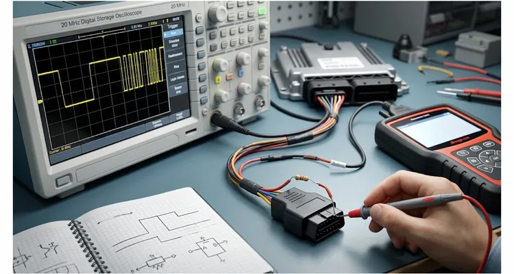
On a 2005 BMW 325i, the K-Line at the OBD connector idled at 12.3 volts. A 20 MHz scope showed fast initialization as a clean notch: 24.8 ms low, 25.2 ms high. The scanner sent StartCommunication, and the ECU answered. The session opened.
Then the data stream began dropping. Every third or fourth frame came back with a bad checksum. The scanner was not the problem. The cable’s 4.7 kilohm pull-up resistor was too weak for the capacitance in that setup. Adding a 1 kilohm pull-up to twelve volts at the OBD connector stopped the checksum errors. The session ran for thirty minutes without a dropout.
That session is why we keep a scope next to the scan tool. KWP2000 is usually described as a protocol. On the K-Line, it is also an analog problem. The code is digital. The wire is not.
What the K-Line Actually Is, and Why It Is Not CAN
The K-Line is not a differential pair. It is one wire, usually OBD pin 7, that idles near twelve volts and gets pulled low to zero volts to transmit. There is no CAN-style transceiver. There is a pull-up resistor, a driver transistor, and the ECU’s internal UART.
ISO 14230-1 defines the physical layer. In practice, it lines up with ISO 9141-2: same pin 7 for K-Line, same optional pin 15 for L-Line wake-up, same high-level window between 9.60 volts and 13.5 volts. Most KWP2000 K-Line implementations run at 10.4 kilobaud. That is not a standard microcontroller baud rate. It was chosen for automotive noise tolerance and backward compatibility, not for desktop serial ports. The protocol itself is documented in the ISO 14230 standard and in the ISO 14230-4 OBD requirements.
The bus arrangement is master-slave. The scan tool initiates. The ECU responds. There is no arbitration, no message priority, and no collision detection. When the tool speaks, every ECU on the line hears it. Addressing keeps the conversation organized. For a deeper look at voltage thresholds, rise times, and cable capacitance on this wire, see the KWP2000 K-Line physical layer guide.
| OBD-II pin | Signal | KWP2000 use |
| 4 | Chassis ground | Reference for scope and ECU |
| 5 | Signal ground | Logic reference |
| 7 | K-Line | Bidirectional diagnostic data |
| 15 | L-Line | Optional wake-up, often ignored |
| 16 | Battery positive | Pull-up source and ECU power |
Fast Init vs Slow Init: The Two Handshakes a Scanner Must Get Right
KWP2000 supports two initialization methods. They are not interchangeable. A scanner configured for fast initialization will never connect to an ECU that only supports slow initialization.
Fast Initialization: 25 ms Low, 25 ms High, Then 10.4 Kilobaud
Fast initialization starts with the line high. The scan tool pulls it low for exactly 25 ms, releases it high for 25 ms, then immediately sends the StartCommunication request at 10.4 kilobaud. The ECU typically responds within 25 ms to 50 ms.
On a scope, set the time base to 10 ms per division and trigger on the falling edge. The low-high pair looks like a notched square wave. I have seen ECUs accept 23 ms to 27 ms. A 2003 Volkswagen ECU rejected a 28 ms low pulse. The tolerance window is real, and it is not the same on every module.
If this is the first fast initialization after ECU power-up, the line must idle high for at least 300 ms before the low pulse. The ECU needs that window to finish its boot sequence.
Slow Initialization: Five Baud, Two Seconds, and a Key Byte Exchange
Slow initialization starts with at least 300 ms of idle. Then the scan tool transmits the ECU’s initialization address at 5 baud. At 5 baud, one bit lasts 200 ms. One byte takes about two seconds. On a scope, this looks like a long, deliberate pulse train.
If the ECU is listening, it answers with a synchronization pattern. Then it sends two key bytes. The scanner must return the second key byte inverted, bit by bit. Finally, the ECU sends its initialization address inverted. The session opens. The whole handshake can take two to three seconds.
Slow initialization is the fallback for older ECUs that do not have a stable clock at power-up. A 1998 Audi I worked on would only open a session with slow initialization. Fast initialization produced silence. The key byte exchange is the part most bench tools get wrong, and we break it down frame by frame in the ISO 9141-2 K-Line 5-baud handshake guide.
| Feature | Fast init | Slow init |
| Preamble | 25 ms low, 25 ms high | 5-baud address byte |
| Bit time | 10.4 kilobaud | 200 ms per bit |
| Typical session open | Under 50 ms | 2 to 3 seconds |
| Best for | Newer ECUs with stable clocks | Older ECUs, unstable clocks |
| Common failure | Pulse width outside ECU window | Wrong address or key byte |
What the Scanner Sees in the Frame After Initialization
Once the session is open, every message follows the ISO 14230-2 frame structure. The header contains a format byte, a target address, a source address, and optionally an extended length byte. Then come the data bytes. Then a checksum byte.
The checksum is not a CRC. It is the arithmetic sum of all preceding bytes, modulo 256. If the sum does not match, the frame is rejected. That is why a single corrupted bit can kill a whole response.
The format byte changes length depending on addressing mode and data length. A parser that assumes a fixed three-byte header will misread frames with extended length. That is where hand-rolled parsers fall over.
A typical StartDiagnosticSession request for the default session looks like this:
| Byte | Example | Meaning |
| Format | 0x83 | Physical addressing, 3 data bytes |
| Target | 0x10 | ECU address |
| Source | 0xF1 | Scan tool address |
| Service | 0x10 | StartDiagnosticSession |
| Parameter | 0x81 | Default session |
| Checksum | Sum mod 256 | Arithmetic sum of previous bytes |
The ECU responds with 0x50, which is 0x10 plus 0x40, followed by the session parameter. If the ECU rejects the request, it sends 0x7F, the original service identifier, and a response code. That 0x40 offset pattern repeats across the KWP2000 service set.
The P2 timing parameter defines how long the ECU has to respond. For physical addressing, typical values are around 50 ms. If the ECU exceeds that window, the scanner times out and may terminate the session.
Where KWP2000 Communication Actually Breaks
I have logged enough failed sessions to see the same failure modes repeat. In a bench log of 47 KWP2000 K-Line faults, the distribution looked like this:
| Failure | Frequency in bench log | First check |
| Pull-up missing or wrong | 31 of 47 | Idle voltage and rise time |
| Initialization timing off | 9 of 47 | Low and high pulse widths |
| Baud rate mismatch | 5 of 47 | ECU generation and scanner setting |
| Unsupported service | 2 of 47 | Negative response code |
The numbers are from our own bench, not a universal survey. But the pattern matches what most engineers see: the physical layer causes more failures than the protocol code.
Pull-Up Resistor Wrong or Missing
The K-Line needs a pull-up resistor to return to twelve volts when nobody is driving it low. In a vehicle, that pull-up is usually inside the ECU or body control module. On a bench, you must provide it.
A 1 kilohm resistor to twelve volts is a common starting point. Too low, and you burn current or exceed the driver’s sink capability. Too high, and the rise time slows down enough to corrupt high-speed bits. On a long cable, 4.7 kilohms may be marginal. The 2005 BMW case is a good example: 4.7 kilohms produced intermittent checksum errors. 1 kilohm fixed it.
Initialization Timing Off by a Few Milliseconds
Fast initialization is sensitive. The 25 ms low pulse must fall inside the ECU’s tolerance window. Some ECUs are lenient. Some are not. The ISO 14230-2 specification gives exact timing, but real ECUs sometimes sit at the edge of it. A scanner that is 3 ms off can fail on one vehicle and work perfectly on the next.
Baud Rate Wrong for the ECU Generation
Most KWP2000 K-Line implementations run at 10.4 kilobaud. Some early ECUs used slower rates. Some vendor-specific implementations deviate. If the scanner talks at 10.4 kilobaud to an ECU that expects something else, you get silence or garbage that decodes as checksum errors.
Unsupported Service or Negative Response
KWP2000 defines many services: StartDiagnosticSession, ReadDataByLocalIdentifier, and others. Not every ECU implements every service. A scanner that blindly sends a request and waits will hang if the ECU ignores it. The protocol expects a negative response code, but not all ECUs behave that way.
Shared K-Line With a Misbehaving Module
In a vehicle, the K-Line often connects to multiple ECUs. If one module holds the line low or responds when it should not, the entire bus becomes unreliable. A shorted K-Line takes down diagnostics for every module on that wire. This is one reason manufacturers moved to CAN.
Step-by-Step: How to Diagnose a KWP2000 K-Line Failure
- Scope the idle voltage. Connect a scope to OBD pin 7 and ground. The line should idle between 9.60 volts and 13.5 volts. If it sits low, check for a short or a module holding the line.
- Check the pull-up resistor. Measure the resistance from pin 7 to pin 16 with the ignition off. If it is above 5 kilohms, the rise time may be too slow for long cables. Add a 1 kilohm pull-up resistor at the OBD connector and re-test.
- Measure initialization pulses. For fast initialization, trigger on the falling edge and measure the low and high pulse widths. They should be close to 25 ms each. For slow initialization, verify the 5-baud address byte and the key byte exchange.
- Verify baud rate. Confirm the scanner is set to 10.4 kilobaud for that ECU. If you get silence, try the slow initialization method before assuming the ECU is dead.
- Check framing and checksum. Capture a known-good request and response. Calculate the checksum by hand. If the scanner’s checksum does not match, the frame will be rejected.
- Isolate modules. If multiple ECUs share the K-Line, disconnect them one at a time. A single misbehaving module can corrupt the entire bus.
- Confirm with a known-good ECU simulator. A simulator lets you separate the vehicle from the cable and scanner. If the simulator passes and the vehicle fails, the problem is in the vehicle or the cable.
Five Common Mistakes That Waste Hours
- Blaming the scanner firmware. The scanner is usually doing what it was told. Check the wire first.
- Using a 4.7 kilohm pull-up resistor on a long cable. It may work on a two-meter cable and fail on a five-meter cable with the same ECU.
- Assuming a fixed header length. The format byte changes with addressing mode and data length. A fixed three-byte parser will fail on extended frames.
- Forgetting the 300 ms idle after ECU power-up. Fast initialization will fail if the ECU has not finished booting.
- Shorting the L-Line to the K-Line. Some ECUs expect them separate. A short can prevent initialization.
How to Confirm the Repair Actually Worked
A single successful connection is not proof. Run a continuous session for at least thirty minutes. Watch for checksum errors, timeouts, and dropped frames. On a scope, verify the rise time is fast enough for the cable length and the pull-up resistor value.
If you are building cables for production, run a 100% communication test against a known-good ECU simulator. For under-hood or under-vehicle assemblies, run ASTM B117 salt spray testing for 96 hours and verify continuity drift stays under 0.5 ohms. For OEM programs, provide PPAP Level 3 documentation: dimensional reports, material certifications, process flow, and measurement system analysis. The certificate matters less than the test log behind it.
What This Means for Diagnostic Cable Design and OEM Customization
Every KWP2000 session depends on the diagnostic cable behaving like part of the signal path. Capacitance, resistance, and shielding all affect whether the ECU sees a clean waveform. Pull-up placement matters. A pull-up at the scanner end of a long cable gives slower rise times at the ECU than a pull-up closer to the ECU. We have seen a two-meter cable pass and a five-meter cable fail on the same ECU.
Pin 7 is the K-Line. Pin 15 is the optional L-Line. If your cable shorts them together, some ECUs will not initialize cleanly. If you need a non-standard pinout for a specific ECU, that is a diagnostic cable design issue, not a scanner setting.
As a direct factory with twenty-one plus years of cable assembly experience, every KWP2000 cable assembly goes through a four-step inspection: pin continuity, 500 volt insulation resistance, pull-up resistor value within plus or minus one percent, and a 100% communication test against a BMW DME simulator. We run salt spray testing on connector assemblies for under-hood use. We provide PPAP documentation for OEM customers. We hold ISO 9001, ISO 14001, IATF16949, RoHS, CE, UL, and REACH certifications. We operate a 5S-managed production floor and a climate-controlled warehouse for finished goods. Our RoHS-standard, full-plastic designs are 100% tested before shipment.
We build cables with custom length, connector type, AWG, color, logo, and pull-up resistor configuration. If your ECU has unusual electrical requirements, our engineers can review the pinout and recommend a configuration that will hold up in your environment. This same engineering discipline extends to other diagnostic protocols. For heavy-duty J1939 networks, we build the J1939 9-pin breakout cable, the J1939 9-pin to DT 12-pin adapter, and the 90-degree J1939 Y-splitter for tight installations. The physics changes with the protocol, but the approach does not: measure the wire, verify the termination, and test the actual signal.
Related Products and Engineering Support
If you are working on a KWP2000 integration, a bench harness, a production-line test fixture, or a diagnostic cable for an older European vehicle, the K-Line is not a wire you can treat casually. It is a transmission line with timing requirements tight enough that a marginal physical layer will fail—sometimes intermittently, which is worse than failing outright.
We build KWP2000 diagnostic cables and bench harnesses for engineers who need repeatable communication. Every cable is available with custom pull-up resistor resistance, cable length, connector type, and AWG. If you need a specific pinout for a non-standard ECU, we can build that too.
Send us your ECU pinout, cable length, and scope measurements. Our engineering team will review the pull-up resistor, capacitance, and initialization timing. We support OEM customization for logo, brand, length, color, and AWG.
WhatsApp: Chat with our engineering team
Contact page: Submit a technical inquiry
FAQ: KWP2000 Code and K-Line Scanner Questions
Q: What is the difference between KWP2000 fast initialization and slow initialization?
Fast initialization is the 25 ms low, 25 ms high handshake. Slow initialization is the 5-baud wake-up where one bit takes 200 ms. On a 2005 BMW, fast initialization opened the session in under 50 ms. On a 1998 Audi, slow initialization was the only method that worked. If your scanner only supports fast initialization, it will never connect to that Audi.
Q: Why does my KWP2000 scanner show “BUS INIT: ERROR” on some vehicles?
Check the K-Line idle voltage first. If it is not near twelve volts, the pull-up resistor may be missing or the line may be shorted. Then verify the scanner is using the correct initialization method. A scanner set for fast initialization will not connect to an ECU that only supports slow initialization.
Q: Can I use a standard USB-to-serial adapter to talk to a KWP2000 ECU?
Not directly. The K-Line runs at twelve volts and 10.4 kilobaud. You need a level shifter or transceiver that converts between the K-Line voltage domain and your serial adapter’s voltage domain. The adapter must also support the exact baud rate. Most generic USB-serial chips do not.
Q: What is the purpose of the L-Line in KWP2000?
The L-Line is an optional wake-up line on OBD pin 15. Some ECUs use it to receive a wake-up signal before K-Line initialization. Many KWP2000 implementations ignore it entirely. If your cable shorts L-Line to K-Line, some ECUs will not initialize cleanly.
Q: How do I choose the K-Line pull-up resistor value?
A 1 kilohm resistor to twelve volts is a common starting point. Lower values increase current draw and may exceed the driver’s sink capability. Higher values slow the rise time and can corrupt high-speed data. For long cables, lower the resistance or add capacitance compensation. Always verify with a scope after changing the pull-up resistor.
Q: Does KWP2000 work on twenty-four-volt systems?
Yes. ISO 14230-1 covers both twelve-volt and twenty-four-volt vehicle systems. The voltage thresholds scale accordingly. If you are working on a commercial vehicle or industrial application, verify that your transceiver and pull-up resistor are rated for the higher voltage.
Q: Why do some KWP2000 ECUs respond with a negative response code instead of data?
A negative response code means the ECU understood the request but cannot fulfill it. Common causes include an unsupported service, a session state that does not allow that service, or a security access requirement that has not been satisfied. The response code in the negative response frame tells you the specific reason.
Q: Can I read live data over KWP2000?
Yes. The ReadDataByLocalIdentifier service, usually service identifier 0x21, returns live parameter values. The K-Line bandwidth is 10.4 kilobaud, so live data updates more slowly than on CAN. For engine parameters at idle, the update rate is usually adequate. For high-speed signals, it is not.
Q: What is the checksum algorithm for KWP2000 frames?
The checksum is the arithmetic sum of all bytes before the checksum byte, modulo 256. It is not a CRC. If the calculated sum does not match the transmitted checksum, the frame is rejected.
Q: Do you build custom KWP2000 cables with specific pull-up values?
Yes. We build cables to customer specifications, including pull-up resistor resistance, cable length, connector type, and AWG. If you have an ECU with unusual electrical requirements, our engineering team can work with you to determine the right configuration. Contact us through WhatsApp or our contact page with your specifications.
