

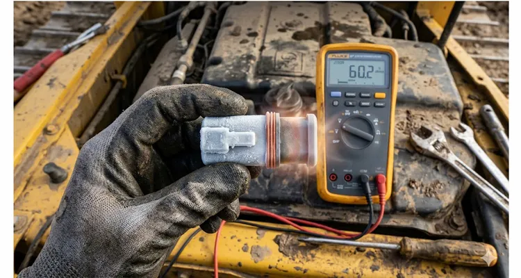
The Fluke reads 60.2 ohms, and for the fifth time that shift, I talked myself into believing it. Pins C and D, cold connector, textbook value. The fact that the same bulldozer had coughed up an ACK error storm four hours earlier, at full oil temperature, was a completely separate problem—or so the desperate brain wants to believe. That gap between the cold-soak resistance measurement and the hot-fault reality is where termination resistance drift lives. It doesn’t reveal itself during a standard continuity check, and it won’t appear on a cold warehouse bench. This article is about capturing that fault at the exact thermal moment it decides to strand a machine.
A parallel resistance calculation assumes the two 120-ohm terminating resistors are thermally static lumps of metal. That assumption survives on a schematic, in a clean-room lab, and nowhere else. A seven-year-old ECU that’s been vibrated, baked, and frozen on the firewall of an excavator doesn’t just have a fixed resistance value; it negotiates that number with the ambient temperature. I’ve logged hundreds of hours on SAE J1939 networks in environments ranging from arctic mining trucks to desert generator sets, and thermal drift of termination resistance is the failure mode I watch technicians misattribute more often than any other physical-layer issue. It’s rarely the primary suspect on a first diagnostic pass. This isn’t a mystery buried deep in the CAN bus protocol; it’s a problem of materials, manufacturing tolerances, and moisture ingress. Let’s walk through the data that doesn’t make it into the maintenance manuals.
A Cold Morning vs. A Hot Haul Truck
A few years back, we were commissioning a fleet of off-highway haul trucks. The J1939 backbone spanned nearly fifteen meters, connecting the engine controller, transmission ECU, instrument cluster, and a telematics gateway. On a frigid morning in Alberta, with the ambient temperature at minus twenty-eight degrees Celsius, the truck would fire up and communicate flawlessly. The initial cold-soak resistance measurement at the diagnostic connector, taken with a milliohmmeter after a proper null and with the batteries disconnected, settled at 59.8 ohms. Life was good.
Four hours into a loaded haul cycle, with the engine bulkhead radiating heat and the transmission housing cooking the chassis harness, the datalink started groaning. We’d see a spike in ACK errors specifically when the transmission tried to send a high-priority torque limit message. We pulled the truck into the bay, killed the master switch, and immediately took another measurement before the metal could cool down. The resistance across the backbone now read 63.1 ohms. That’s a shift of over three ohms, roughly a five percent delta.
On paper, a CAN node with a typical CAN transceiver like the TJA1040 has an input impedance leakage that can tolerate a bus load deviation. But on a long backbone with multiple stubs, splices, and slightly corroded ground eyelets, that five percent thermal drift pushed the differential voltage at a specific, partially-terminated node right into the grey zone of the receiver’s hysteresis. The result was intermittent, heat-induced bus contention. It wasn’t a hard failure; it was a soft, maddening negotiation between physics and a PCB’s temperature coefficient.
The Physics Inside the Plastic Shell
Stop thinking of a terminating resistor as a discrete, perfect 120-ohm component. It isn’t. It’s an assembly. Inside the sealed overmold of a typical Deutsch DT-series termination cap, you’ll find a thick-film chip resistor, or sometimes a wire-wound element, soldered to brass terminals. The whole affair is then potted in a thermoplastic elastomer.
When we talk about resistance drift, we’re primarily talking about the Temperature Coefficient of Resistance (TCR). A generic thick-film resistor might have a TCR of ±200 parts per million per degree Celsius. A high-quality metal-film resistor might get you down to ±25 ppm/°C. If a low-tier termination cap uses a cheap resistor with a +180 ppm/°C spec, and its local environment goes from -20°C to +85°C—a 105-degree swing—the resistance change is mathematically non-trivial. You’re looking at a theoretical shift of over two ohms just from the resistor element itself, before you even account for the solder joint resistance changing or the spring tension in the terminal relaxing with heat.
I’ve cross-sectioned failed J1939 terminators and found something the datasheets won’t tell you: micro-cracks in the solder meniscus. These form over hundreds of thermal cycles. When the unit is cold, the solder contracts just enough to force the cracked faces into contact, and you read a faithful 120 ohms. When it gets hot, the metal expands, the crack gap opens by a few microns, and you suddenly have a high-resistance series fault that transforms your terminator into a wobbly, temperature-dependent phantom. Measuring it cold on the bench is a perfect trap; the data will lie to you with absolute confidence.
The Thermal Sweep: A Differential Diagnosis for Resistors
A single ambient measurement captures a static failure, not an intermittent one. You have to catch the component lying. The following procedure isn’t a standard multimeter check; it’s a deliberate thermal stress test adapted from our in-house component validation process. You can adapt this for a field diagnostic if you have a bit of patience and a heat gun—though exercise extreme caution around fuel lines and plastic connectors.
Step 1: Isolate the Suspect Terminator from the Backbone
Your measurement is only as good as your isolation. The bus’s common-mode choke and any undischarged capacitors in the ECUs will skew your reading. Unplug the termination resistor. Let it sit for ten minutes to normalize.
Step 2: Take Your Reference Cold Measurement
Record the ambient temperature with an infrared gun pointed at the terminator’s body. Use a four-wire Kelvin measurement if you have the gear; if not, null out your multimeter leads religiously. Record this value, for example, 120.3 ohms at 22°C.
Step 3: Apply a Controlled Thermal Step
Seal the terminator in an anti-static bag and submerge it in a controlled-temperature bath, or if you’re in the field, use a heat gun on a low setting from a distance of twelve inches, rotating the part constantly to avoid hot spots. You’re not trying to melt it; you’re aiming for a surface temperature representative of the engine firewall after soak—somewhere around 80°C to 90°C. Monitor the case temp with your IR gun.
Step 4: Watch the Drift Curve in Real-Time
As the temperature crosses 60°C, you should see a stable, linear change if the TCR is well-behaved. If the resistance reading suddenly jumps by 5% to 10% over a narrow five-degree band, or if it becomes noisy and flickering, you have caught the mechanical solder-crack fault in the act. A healthy thick-film terminator will drift gently; a fractured one will show a non-linear drift signature, a staircase-like pattern. We reject any unit where the hot resistance deviates by more than one percent from the predicted TCR curve. In a truck that cannot tolerate downtime, that one percent margin is your peace of mind.
The Five Paths to a ‘No Fault Found’ Diagnosis
I’ve reviewed warranty-returned termination caps where the attached failure analysis report read “No Fault Found.” That’s almost always an indictment of the bench test method, not the component. Here are the five diagnostic paths that most reliably produce that misleading result, and how to avoid each one.
Path 1: Measuring In-Circuit with the Batteries Connected
J1939 nodes often have internal bias resistors pulling the bus to 2.5V. Your ohmmeter injects a small current, and the active semiconductors distort the reading completely. You’re reading the resistance of a silicon junction, not the terminator. Disconnect the master switch and wait for the bus capacitors to bleed down before probing.
Path 2: Ignoring the Zero Offset
I’ve watched seasoned techs use a meter with corroded probe tips that add 1.2 ohms of lead resistance, then proudly write down “121.0 ohms.” A true 120.0-ohm terminator with a 1.2-ohm offset reads 121.2. That’s an apparent error that gets misdiagnosed as a drifty resistor. Touch the probes together and zero the meter before every measurement sequence.
Path 3: The Quick Touch Test
Unplugging the connector, touching the probes for half a second, and saying “yep, sixty” misses the fact that thermal equilibrium hasn’t been reached. The internal resistor chip can be much hotter than the connector body you’re touching. Give the reading a full thirty seconds to stabilize while the measurement current settles through any oxide layers.
Path 4: Confusing System Termination with Component Termination
You measure 60 ohms at the diagnostic port and assume both ends are good. You could have one perfectly healthy 120-ohm terminator at the engine end and a completely open circuit at the cab end, masked by the fact that several ECUs in the middle have partial 2.5k ohm or 4.7k ohm bias-split resistors that bring the parallel combination down coincidentally near 60 ohms. Always unplug and measure each terminator individually. This is a classic phantom fault that we’ve traced back to termination and stub length mismatches on more than one occasion.
Path 5: Using the Wrong Resistor Type in a Repair
I’ve seen a splice repair where a technician soldered in a generic carbon-composition resistor and wrapped it in electrical tape. A carbon comp resistor with a 1200 ppm/°C negative TCR could swing wildly and absorb moisture, turning the bus into an unreliable antenna. The J1939 standard demands stability that only a metal-film resistor or quality thick-film resistor, hermetically sealed component can provide.
Proving the Fix Before You Release the Machine
After you’ve replaced a suspected terminator—or better yet, upgraded to a sealed OEM-spec termination resistor—you don’t just start the engine and walk away. You need to exercise the thermal fault. Reconnect everything and take a cold baseline of 60 ohms at the diagnostic connector. Start the machine and get everything heat-soaked. While watching live bus statistics—specifically the Rx error count and Tx error count on a gateway module—apply a load. Run the engine to high idle, engage the hydraulic pump, and let the coolant temperature climb.
If your original error counters were incrementing during the heat-soak phase, a stable replacement will show a flat line. Zero additional errors. Then, perform a wiggle test on the harness near the connector while the bus is hot and active. A robust termination assembly with compliant gold-plated terminals won’t show a single transient spike. If it does, your problem was never the resistor; it was the harness crimp, and the thermal drift of the resistor was just amplifying a high-resistance joint fifty centimeters upstream. This is exactly the kind of intermittent J1939 fault that a wiggle test protocol is designed to isolate.
The Internal Difference That a Thermal Shock Screen Reveals
On a warehouse shelf, a cheap terminator and a precision OEM terminator look interchangeable—same black polyamide overmold, same keyed connector body. The difference only emerges inside a thermal chamber. We manufacture against a single unforgiving metric: the non-linear drift signature. This isn’t about hitting a static 120 ohms on a pass/fail rig; it’s about plotting a clean, linear TCR curve from -40°C to +125°C. A unit with a latent solder fissure shows a staircase pattern on this plot, a jagged line that a static room-temperature tester calls “perfect.”
We produce these J1939 termination resistors not as afterthoughts, but as critical network components. The process starts with the resistor element itself—we don’t use commodity off-the-shelf chips for heavy-duty applications. We specify low-TCR thin-film elements when the application demands it. The terminal-to-resistor connection isn’t a simple hand-soldered joint; it’s a controlled resistance welding process that eliminates the solder creep and thermal fatigue issues I described earlier. The overmolding isn’t just a plastic boot; it’s a two-shot process where a hard inner shell provides mechanical strain relief and a soft outer TPU jacket seals against the mating connector with an environmental rating that holds up in a salt-spray chamber for 96 hours.
Every batch leaves the factory with a four-point inspection that includes a 100% thermal shock screen, not just a sample test. We cycle them from -40°C to +125°C and look for that non-linear drift signature in real-time. This is data we track by lot number. For a fleet manager dealing with an intermittent network, having that lot traceability and a certificate of conformance showing the actual measured TCR curve is the difference between a blind swap and a validated engineering fix.
Frequently Asked Questions
Does a J1939 network always need exactly two terminators?
Classically, yes, one at each extreme end of the J1939 backbone. However, some modern architectures with distributed gateways can split the network into segments, each requiring its own pair of terminators. Always consult the specific vehicle’s network topology diagram.
Can I measure termination resistance with the network awake?
No, and you’ll risk damaging sensitive CAN transceivers if you’re on a resistance setting with enough compliance voltage. The bus must be unpowered, and all ECUs must be allowed to discharge their internal bus capacitors for at least thirty seconds after disconnecting the master switch.
What is the acceptable tolerance for a 120-ohm terminator?
The standard for heavy-duty applications typically calls for ±1% or better. Tighter tolerances directly improve the differential voltage margin, especially on long branches.
Will a 5% drift really bring down my entire bus?
On a short, pristine bench setup, maybe not. On a real vehicle with years of corrosion, multiple stubs, and vibration-worn wiring, that 5% resistance drift can erode the noise margin sufficiently that a high-current injector solenoid switching nearby will induce enough common-mode noise to slam the bus into error-passive mode. This is precisely the failure mechanism we documented in our deep-dive on 0.3V ground offset on a J1939 backbone and how to diagnose J1939 ground offset before it cascades into a fleet-wide issue.
Is there a difference between a diagnostic connector reading and an end-of-line terminator reading?
Profoundly, yes. The diagnostic port reading sees the parallel combination of all termination and biasing on the backbone. To verify an individual terminator, you must unplug it. No shortcuts.
Can I build my own terminator in a pinch?
You can, but in a production environment, this is a liability. A hand-made unit lacks the environmental sealing and mechanical strain relief that prevents the cold-solder failure mode. It’s a diagnostic step to prove a fault, never a permanent repair.
Why do some terminators have three pins?
You’re likely seeing an implementation that ties the split termination to the shield pin, usually with a 1nF capacitor. This shunts high-frequency noise to ground through the shield. It’s not a simple resistor; measuring pin-to-pin without understanding the shield path gives a nonsense reading. If you’re chasing noise-related faults, a J1939 waveform analysis with a 200-dollar USB scope will show you exactly what’s coupling onto the bus.
How does moisture ingress affect the reading?
Moisture creates an ionic leakage path in parallel with the 120-ohm resistor. You might read a lower resistance initially that slowly climbs as the measurement current electrolytically dries out the contaminant. If your resistance reading is a slow-moving target, you have a sealed connector that has failed.
From a Bench Diagnosis to a Validated Factory Fix
Chasing an intermittent CAN bus fault that only appears under thermal load often ends with a decision: swap the part with an identical commodity unit and hope, or validate a component with its own traceable TCR curve. Our manufacturing and direct-support model exists for the second path. We don’t stock a web catalog with prices because the conversation usually starts with a network topology sketch, an environmental profile, and a request for a sample that has passed a 100% thermal shock screen with documented lot data. This is the same approach we outline in our guide to J1939 physical layer troubleshooting using a 60-ohm waveform, where component-level validation replaces guesswork.
We ship heavy-duty J1939 termination resistors and J1939 connectors globally directly from our ISO/TS-certified facility, where we maintain climate-controlled storage for all polymer components and enforce a 5S manufacturing discipline that ensures every soldered joint and welded terminal is batch-inspected. Our quality management system is built around three internationally recognized standards: IATF 16949:2016 for automotive quality management, ISO 14001:2015 for environmental management, and ISO 1298-2 for material traceability and process control. If you need a custom termination resistor with a specific cable length, a custom color overmold for your branded harness, or a validated TCR test report for your incoming inspection documentation, that’s the conversation we have every day.
If you’re chasing a tricky network fault and want to compare notes with someone who builds these components, not just resells them, the most direct way to reach an applications engineer is through WhatsApp. You can send a message directly to my colleague Linda at the factory, and she can put you in touch with a technical team member who can review your J1939 network topology drawing and thermal data.
Chat with Linda on WhatsApp for Engineering Support
Alternatively, if you have a detailed specification drawing, a target quantity, and require a formal quotation or a sample for thermal validation on your own test bench, the best path is through our contact page. That goes directly to our OEM support desk where we log and track every custom termination project request.
Submit Your Custom Termination Project via Our Contact Page
A J1939 backbone is only as stable as its weakest physical layer component. The terminating resistor that reads perfectly on a cold bench but opens up under thermal load is a design flaw, not an inevitable feature of aging. Fixing it starts with the right termination resistance measurement method, and often ends with a component built to a standard that doesn’t cut corners on the coefficient of resistance. We’re here if you need that kind of component.
