

The maintenance manager had set up two folding chairs in front of the excavators, like he was waiting for a tennis match to start. His coffee had gone cold sometime around 5:30 a.m. When I pulled up at seven, he didn’t say hello. He just pointed at the machine on the right and said, “That one. Exactly 1,800. Every time.”
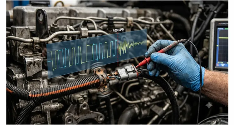
He had two identical excavators sitting side by side in the Arkansas sun. One ran like a sewing machine. The other would drop the entire CAN bus at precisely 1,800 rpm—every single time—but only after about twenty minutes of runtime. Not at 1,790. Not at 1,810. Right at 1,800.
The J1939 fault codes were a scrambled mess: lost communications with the engine ECU, implausible data from the aftertreatment controller, intermittent suspension controller timeouts. The local dealer had already thrown an engine ECU and a complete engine harness at the problem—north of twelve thousand dollars in parts and labor, all told. No change.
This is the kind of fault that makes good technicians doubt their own scope traces. It’s also the kind of fault that teaches you more about wiring harnesses than any textbook ever will. What follows is a field guide drawn from chasing these exact gremlins across agricultural machinery, construction equipment, and a handful of marine applications. If you’ve landed here with a machine that only acts up at a specific rpm, you already know the frustration. Let’s walk through what’s actually happening and how to find it before you fire the parts cannon again.
Why 1800 RPM Keeps Showing Up in Your Fault Logs
At 1,800 rpm on a six-cylinder four-stroke, the third-order firing frequency crosses 90 Hz. If you’ve got a harness section with a first-mode natural frequency anywhere near that—and I’ve measured plenty in the 85 to 95 Hz range on actual equipment—the input energy stops being something the harness can absorb and starts being something that drives it. The engine’s firing frequency combines with chassis resonance to produce a sharp, narrow-band vibration peak. When that peak aligns with a harness segment’s own natural frequency, a minor intermittent open turns into a hard open circuit. This is the same principle behind mechanical resonance that governs everything from bridge oscillations to crankshaft torsional vibration—when the driving frequency matches the natural frequency, amplitude multiplies.
I’ve seen this most often on machines that spend hours working at a governed speed. Wood chippers running at 1,800 rpm for ten hours straight. Irrigation pump engines locked at that speed all season. Generator sets that sit at 1,800 rpm for days on end during an outage. The harness isn’t faulty at idle. It’s not faulty at full throttle. It only acts up when the vibration energy concentrates right where the harness can’t handle it.
The typical symptom profile:
- The bus goes quiet for milliseconds, just long enough to log a J1939 timeout. Not long enough for the operator to react—just long enough for every ECU on the bus to register the dropout.
- Fault codes scatter across multiple controllers, because it’s the communication backbone that’s dropping out, not a single sensor. If your diagnostic scan tool pulls codes from three different ECUs with timestamps within half a second of each other, you’re looking at a bus event, not a component failure.
- The engine may stutter or briefly derate, then recover before the operator can even put a hand on the throttle. Ask the operator: “Does it feel like someone tapped the brakes for a split second?” That’s the bus dropping and the engine ECU defaulting to a limp-mode fuel map for a few combustion cycles.
- The problem might disappear for a week, then come back on a day with different ambient temperature. Harness jacket stiffness changes with heat—a jacket that’s soft at 90°F shifts the resonant frequency just enough that the fault moves. I’ve tracked faults that appeared at 1,800 rpm on cold mornings and 1,820 rpm after the engine bay heat-soaked.
What’s Actually Failing Inside the Harness
Not all intermittent opens are the same. After cutting open more suspect harnesses than I care to count, I’ve learned to look for three distinct failure modes that love vibration-induced opens.
1. Strand Fatigue at the Termination Point
Where a wire enters the back of a Deutsch connector or Ampseal connector pin, the copper strands flex microscopically with every vibration cycle. Over hundreds of hours at that resonant frequency, individual strands fatigue and snap—usually just behind the crimp barrel.
I’ve cut open harnesses where seven of the nineteen strands were gone—clean fatigue fractures—and the insulation jacket didn’t show a mark. The remaining twelve strands carried enough current to pass a continuity test. A multimeter would call it good. Under vibration, the gap opened and the bus died for milliseconds, then closed again. The insulation acts like a return spring, pulling the broken ends back together when the load comes off. That’s why the fault vanishes at idle. The spring closes. The circuit heals. Until the next time the engine hits 1,800.
2. Fretting Corrosion in Connector Terminals
Vibration at a specific frequency can cause the male and female terminals to move relative to each other on a micrometer scale. This micro-motion generates oxide debris at the contact interface—a phenomenon well documented in the broader field of fretting wear studied across aerospace, automotive, and industrial connector applications. Tin oxide is an electrical insulator. Gold oxide is less problematic but still degrades contact resistance. Once enough debris builds up, you get a high-resistance connection that only shows itself when the vibration hits just right.
I’ve measured terminal resistance on a Size 16 Deutsch connector that jumped from 0.3 ohms at idle to over 2 kilohms at 1,800 rpm—essentially an open circuit as far as the CAN transceiver is concerned. At 2 kilohms, the differential voltage collapses below the recessive threshold, and every ECU on the bus interprets it as a loss of communication.
3. Internal Harness Splices with Cold-Weld Failure
Factory splices inside the harness are usually ultrasonic welded or crimped and then overmolded. If a splice is poorly positioned at a hard point in the harness routing, vibration can concentrate stress right at the weld joint. The weld fractures internally, creating an intermittent open that’s thermally sensitive and vibration dependent.
These are the hardest to find because you can’t see the splice without stripping the harness jacket, and the fault comes and goes. The splice looks fine from the outside. The overmold is intact. But underneath, half the weld cross-section has turned into micro-cracks that open and close with every vibration cycle.
Finding the Fault Without Firing the Parts Cannon
You’re not looking for a fault. You’re looking for the conditions under which the fault can’t hide anymore. Start by making the fault as reproducible as possible—same rpm, same runtime, same load. Then start removing variables one by one. Every time you remove something from the circuit and the fault stays, you’ve eliminated a branch. When the fault finally disappears after removing a connector, you’ve just found where the problem lives.
Here’s the diagnostic sequence I follow:
Step 1: Let the codes tell you it’s a bus problem, not a component problem.
Clear all J1939 fault codes and run the machine at the problem rpm until the fault reappears. Write down only the codes that come back. Then ignore any code that points to a sensor rationality fault—if the bus drops, the ECUs lose data and will flag bogus sensor faults. What you care about are communication loss codes: J1939-9 timeouts, DM1 messages indicating lost controllers, CAN Bus Off events. If you see three or more controllers reporting communication loss within a one-second window, you are not hunting an ECU failure. You are hunting a wiring failure.
Step 2: Scope both CAN hi and CAN lo simultaneously.
Backprobe at the diagnostic connector with a two-channel oscilloscope. Set your timebase to see individual frames—100 µs/div works well for 250 kbps J1939. Run the engine to the problem rpm and watch. If the harness is opening, you’ll see the differential signal collapse. Both lines will drift toward the recessive voltage of around 2.5 V. A healthy termination keeps the differential voltage swinging between roughly 1.5 V and 3.5 V during a dominant bit. When one wire opens, you lose that swing, and the differential collapses toward zero. That collapse, even if it lasts only 200 microseconds, is your smoking gun. For a deeper walkthrough on setting up this exact measurement, see our J1939 oscilloscope waveform diagnostics guide.
Step 3: Manipulate the harness while scoping.
With the scope running and the engine at the problem speed, have someone systematically move the harness by hand—bend it gently near connectors, wiggle sections that pass near engine mounts or hard frame points. If you can make the fault appear and disappear by manipulating a specific section of the harness, you’re very close. I use a wooden dowel to apply pressure to specific points without risking a shock or short. When the scope trace jumps at the exact moment the dowel presses a particular bend, you’ve just located the failure within inches. This is the wiggle test protocol we formalized after years of chasing intermittent opens—if you want the full procedure, it’s documented there.
Step 4: Isolate the segment by elimination.
The J1939 backbone runs from controller to controller with termination resistors at both ends. Unplug connectors one at a time to eliminate branches. If the fault remains with only the engine ECU, transmission controller, and the two terminators in the circuit, you’ve narrowed the harness section dramatically. If the fault disappears when you disconnect a particular branch, that branch’s stub harness is the suspect. Keep in mind that J1939 termination and stub length directly affect signal integrity—a stub that’s too long can cause reflections that mimic intermittent opens.
Step 5: Confirm with a resistance wobble test.
With the engine off, connect a milliohm meter across the suspect wires—CAN hi end to end, CAN lo end to end. Have someone rock the harness at the suspected failure point while you watch the meter. A healthy CAN line under two meters long should be under 0.5 ohms and stay stable. If you see it jump by an ohm or more when the harness flexes, you’ve found the bad section. The resistance jump doesn’t need to be dramatic. On a CAN bus, a 2-ohm transient is enough to cause frame errors when combined with the inductive kick of an injector firing.
Five Mistakes I’ve Watched Good Technicians Make
1. Replacing ECUs based on timeout codes.
If multiple controllers all go offline at the same moment, the odds that all of them failed simultaneously are effectively zero. I watched a fleet spend forty-three thousand dollars on engine ECUs—three of them—before anyone scoped the CAN lines. Every single ECU that was replaced was fine. The problem was a cracked solder joint inside a terminating resistor that opened only when the engine mount heated up. The common element in simultaneous timeouts is always the bus itself—the wiring. Before you authorize another ECU replacement, read how a 23-cent resistor caused fleet downtime that nearly bankrupted a small logging operation.
2. Ignoring the termination resistors.
I’ve seen people chase an intermittent fault for days only to discover that one of the terminating resistors had a cracked internal connection that opened only with vibration. Measure termination resistance with the power off. You should see around 60 ohms—that’s two 120-ohm resistors in parallel. If it reads 120 ohms, one terminator is completely open and the bus is running single-terminated. A single-terminated CAN bus will still sort-of work but becomes hypersensitive to any line disturbance. Every injector pulse becomes a potential bus error. This gets worse with temperature—termination resistance drift between hot and cold can push a marginal terminator over the edge.
3. Shotgun-replacing the entire harness without understanding the failure.
Yes, a new harness often fixes the problem—temporarily. But if the root cause is a harness routing issue that places the harness at a resonant point, the new harness will fail the same way in similar hours. I’ve seen fleets chase this in circles: replace the harness, get six months of clean running, then the same codes come back. The harness wasn’t defective. The routing was.
4. Probing with a multimeter instead of a scope.
An intermittent open at 90 Hz is invisible to a digital multimeter. The meter averages, and you’ll see 2.5 V sitting there looking perfectly healthy. The fault lasts three milliseconds. The meter samples every 400 milliseconds. Do the math—you will never catch it. Use a scope, or you’re working blind. If you’re weighing whether your fleet can justify an oscilloscope, we ran the numbers on fleet oscilloscope cost-benefit—the ROI lands faster than most maintenance managers expect.
5. Crimping a new terminal onto oxidized copper without cleaning it.
If you find a broken wire at a connector and simply crimp a new pin onto the same old copper without cutting back to bright material, you’ve built in a high-resistance connection that will haunt you later. The oxidation layer acts as a semiconductor—it passes enough current to fool a continuity test but breaks down under load. Cut back at least an inch beyond any discolored copper. If the wire looks dull instead of shiny, keep cutting. This is one of the most common field repair mistakes we see in forestry equipment, where harnesses take constant vibration punishment.
How to Know You’ve Actually Fixed It
A successful repair isn’t just clearing the codes and taking a lap around the yard. I run a specific validation cycle designed to expose a marginal fix:
- Cold soak the machine overnight, then run it from a cold start straight to 1,800 rpm and hold for at least thirty minutes. The thermal expansion from cold to hot changes the geometry of the harness slightly and can hide a repair that’s marginal. A crimp that’s solid at 70°F might open at 180°F when the engine bay heat-soaks and everything expands.
- Operate the machine under load at the problem rpm, not just in neutral. On a machine with a hydraulic pump loading the engine, the vibration signature under load is different from unloaded conditions. The torsional vibration from a loaded crankshaft is an entirely different animal from the smooth hum of an unloaded engine. I’ve had repairs pass the unloaded test and fail the moment the hydraulic system demanded full pressure.
- After repair, scope the CAN bus again and verify that differential voltage swing remains robust across the entire rpm range, from idle to high idle. There should be no dropouts, no glitches, no change in signal amplitude. If the differential voltage drops by more than 0.3 V at any rpm compared to baseline, you still have a marginal connection somewhere. Pay attention to J1939 waveform analysis—a healthy waveform has clean, sharp transitions, not rounded shoulders.
- Run a DM1 request with a diagnostic tool after the test cycle and confirm zero active communication faults. One communication fault on a single controller suggests you missed a branch. Three or more faults across multiple controllers means you didn’t find the root cause.
If the machine passes all four checks, the fault is gone. If it comes back in three months, you didn’t find the root cause—you only found one damaged spot. Go back and check routing.
What Separates a Harness That Survives Resonance from One That Doesn’t
After years of dissecting failed harnesses, I can say with confidence that the difference comes down to manufacturing details that aren’t obvious from the outside.
Crimp Quality at the Terminal
A properly crimped terminal has a gas-tight connection between the copper strands and the terminal barrel—the strands and the barrel effectively become one piece of metal. This requires precise die geometry, calibrated crimp force, and copper that hasn’t work-hardened from sitting in a warehouse for years.
When we quarantine a batch of crimps because the pull-force test shows a three-percent deviation, that batch never reaches a customer. The test equipment logs the data automatically. You can ask for that data if you’re qualifying us as a supplier. We don’t ship harnesses that might be fine—we ship harnesses we know are fine, because we measured every critical parameter. That’s not theory. It’s the kind of process you build when you’ve been manufacturing harnesses for over twenty years and you’re tired of field failures.
Strain Relief Design
Where the wire enters the connector backshell, the transition must be gradual. A sharp bend at that point concentrates stress exactly where the copper exits the crimp barrel—the very spot where strand fatigue loves to start. We specify a minimum bend radius of five times the outer jacket diameter for the first inch from the connector, and we use boots or overmold transitions that support the wire without creating a hinge point. A hinge point is a fatigue point waiting to happen.
Wire Spec and AWG Selection
J1939 specifies twisted pair with a characteristic impedance around 120 ohms, but it doesn’t specify strand count or conductor alloy. Nineteen strands instead of seven improves flex life dramatically—more strands mean less strain per strand per flex cycle. We’ve moved many OEM customers toward high-strand-count conductors in sections of the harness that see vibration, especially the engine harness to frame interface where relative motion between the engine and chassis creates constant flex.
Production Environment Matters More Than Most Buyers Realize
A harness built in a shop without climate control will have slightly different strip lengths and insulation compression when the temperature swings from morning to afternoon. That variability means some harnesses in a batch will be more susceptible to vibration-induced opens than others—and you won’t know which ones until they fail. Our facility operates under climate-controlled assembly areas, not because it sounds good on a brochure, but because we’ve measured the difference it makes in pull-force consistency and terminal retention. When the room temperature holds steady at 22°C, the insulation strips the same way at 8 a.m. as it does at 4 p.m. That consistency shows up in the field as reliability.
The Fleet of Concrete Mixers That Taught Me All of Thi
There was a fleet of fifteen concrete mixer trucks in the Midwest—all identical, all new within eighteen months. Three of them started logging random J1939 communication faults, always when the drum was spinning at mixing speed, which meant the engine sat at roughly 1,800 rpm.
The first two trucks got full engine harnesses under warranty. The problem came back within six months on one of them—the exact same codes, the exact same rpm window. When the third truck started acting up, the fleet manager called us directly instead of going back to the dealer.
We spent a day on one truck with a scope. It was February, maybe 20°F in the yard, and I remember the sound of that engine stumbling—a half-second hesitation, like a cough, then smooth again. The CAN bus looked perfect at idle, perfect at 1,500, and at 1,800 it would randomly drop frames. Sometimes one missed frame every few seconds. Sometimes clusters of fifty missed frames in a row. Wiggling the harness where it passed over the left engine mount made the fault appear and disappear on command—I could trigger it with a finger.
We cut open that section of the original harness. Inside, a factory splice for the CAN hi line sat directly on top of a hard plastic support clip, zip-tied tight. The clip concentrated engine vibration right into the splice joint. Under magnification, you could see fatigue cracks radiating through half the weld—the copper inside looked like a dry riverbed. The remaining connection held at idle but separated the moment resonance hit.
The fix wasn’t another factory harness routed the same way. We built a replacement engine harness with the splice relocated to a low-vibration area near the frame rail, with a service loop that absorbed engine-to-frame flex, and with redundant strain relief at every connector. The fleet upgraded all fifteen trucks. That was three years ago, and not a single J1939 communication fault has returned.
This case is one of many that shaped how we think about J1939 backbone design—get the physical layer right, and the network stops generating phantom faults that cost thousands in misdirected diagnostic labor.
When an Off-the-Shelf Harness Won’t Solve It
If you’re dealing with a machine that has unique vibration characteristics—aftermarket engine swaps, repowers, or equipment that operates continuously at a narrow rpm band—a standard replacement harness may just re-create the conditions that caused the failure. The harness design itself is the root cause.
We work directly with fleet managers, equipment rebuilders, and OEM engineering teams to build custom harnesses that account for the specific vibration profile of the application. That conversation starts with questions nobody asks at the parts counter: What rpm does this machine hold for extended periods? Where is the harness routed relative to engine mounts, frame rails, and hard points? Have you measured the dominant vibration frequency on this chassis, or are we going to model it from the engine firing order? What connectors are in use, and what is their ingress protection requirement?
If you’re chasing a repeat J1939 fault that seems to defy logic, it may not be your diagnostic skills—it may be the harness design itself working against you. Reach out directly, and we can talk through what you’re seeing. No sales script, no upselling. I’d rather spend half an hour helping you identify the fault than have you throw another ECU at it.
→ Tell us what the machine is doing: Get in touch on our Contact page
→ Prefer to message directly? Chat with us on WhatsApp
Hardware That Makes J1939 Diagnostics Faster
While every harness failure has a unique fingerprint, some hardware elements show up in the repair process often enough to deserve a mention:
- J1939 diagnostic breakout cables: Allow you to monitor CAN traffic without backprobing connectors repeatedly—every backprobe penetration is a potential future failure point. We supply these in custom lengths and with various diagnostic connector pinouts. A 9-pin pigtail breakout cable lets you tap into the bus cleanly without piercing insulation, which matters when you’re scoping for intermittent events over hours of runtime.
- Deutsch and Ampseal terminated stub harnesses: For field repairs where you need a section of CAN backbone with correct impedance and proper connectors already terminated. No field crimping, no guesswork on strip length. If you’re working extensively with these connector systems, our Deutsch DT and HD connector guide covers selection, assembly, and common failure points. For installations in confined spaces where a standard straight connector puts stress on the wire exit, a 90-degree right-angle Deutsch adapter can eliminate the sharp bend that starts strand fatigue.
- Custom engine-to-frame harnesses: Designed with your routing constraints, vibration profile, and connector layout in mind. OEM branding and custom color coding are standard options.
If your quality system requires supplier documentation—ISO 9001, ISO 14001, IATF 16949, RoHS, REACH—we provide it as part of the engineering package, not as a sales brochure. What matters more is that the harness you receive was built in a climate-controlled environment where every crimp is monitored in-process, every assembly passes continuity testing, and a sample from every batch gets pulled to failure. Full-plastic overmold designs eliminate corrosion paths by removing every metal-to-moisture interface. We’ve been doing this for over twenty years because we got tired of seeing field failures that shouldn’t have happened.
FAQ: Intermittent J1939 Faults at 1800 RPM
1. Why does the fault only happen at 1,800 rpm and not at other speeds?
The engine and chassis have a natural vibration mode that peaks at that rpm. When the driving frequency from the engine’s firing order aligns with a harness segment’s own resonant frequency, the vibration amplitude at that segment multiplies. It’s the same physics that makes a tuning fork ring at only one pitch—the harness segment resonates only when the input frequency matches its natural frequency.
2. Can a bad battery or alternator cause J1939 communication faults?
Excessive AC ripple from a failing alternator can introduce noise on the CAN lines that corrupts individual frames, but it usually affects all rpm ranges, not just a narrow band. If your fault is locked to a specific rpm, you’re almost certainly chasing a vibration-triggered open, not a power supply issue. Scope the alternator output for ripple anyway—it takes five minutes and eliminates a variable.
3. How do I tell the difference between an open on CAN hi versus CAN lo?
With a scope, if CAN hi opens, you’ll see the CAN hi voltage float toward ground or the recessive state while CAN lo remains active and continues toggling. A CAN lo open pushes CAN lo toward the recessive voltage while CAN hi keeps switching. Either one kills the differential signal, but identifying which line is failing tells you exactly which pin to inspect at the connector.
4. Is there a way to temporarily bypass a suspected section of harness?
You can run a temporary twisted-pair overlay harness between the two nearest connected ECUs, but you must maintain the 120-ohm characteristic impedance and proper termination. Use twisted pair, not random primary wire twisted together by hand. Keep the overlay away from ignition coils, alternator cables, and injector wiring—electromagnetic interference on an untwisted overlay will create its own set of ghost faults. If you need a permanent field-repair strategy, we cover harness protection methods for high-vibration environments in a separate guide.
5. Can a bad ECU termination resistor cause this?
Yes. Some ECUs have built-in software-switchable termination. If that resistor circuit cracks internally—a solder joint, a trace, the resistor element itself—it can open only under vibration, mimicking a harness break perfectly. Measure termination resistance cold and after heat-soaking the ECU with the engine running. If it changes, the problem is inside the ECU, not the harness. We’ve documented the exact measurement procedure in our guide on J1939 termination resistance drift hot vs. cold.
6. Does ambient temperature really affect these faults?
Yes. Harness jacket stiffness changes with temperature—PVC and XLPE both get more flexible as they heat up. A stiffer jacket at cold temperatures shifts the resonant frequency upward slightly. A fault might appear at 1,800 rpm when cold but move to 1,820 when hot, or disappear entirely. If the fault seems to come and go with the weather, you’re not imagining it. The physics is real.
7. What’s the most productive first test when I suspect a vibration-induced open?
Set up a scope on the CAN bus and deliberately manipulate the harness while the machine runs at the problem speed. It’s the fastest way to localize the fault—often faster than any scan tool diagnostic routine. If wiggling a specific section triggers the fault, you’ve found your failure point in minutes rather than hours. For a step-by-step walkthrough of this exact technique, see our intermittent J1939 faults wiggle test procedure.
8. Are aftermarket harnesses as good as OEM?
The better question is: does the harness impedance profile match the original across the full operating temperature range, not just at room temperature? A harness that measures 120 ohms on the bench but drifts to 140 ohms when the engine bay heat-soaks will cause signal reflections and intermittent errors. OEM harnesses aren’t automatically better, but they’re usually validated for that temperature sweep. If your aftermarket supplier can show you impedance measurements from minus 40 to plus 125 Celsius, the harness will perform. Ask for the data.
9. How can I prevent J1939 harness faults in a fleet of machines?
Route harnesses away from hard mounting points. Use flexible service loops at every transition where the harness crosses from the engine to the frame. Inspect harness support clips for wear at scheduled intervals—a broken clip turns a supported harness into a free-hanging harness that vibrates at a completely different frequency. When a harness is replaced, avoid zip-tying it too tightly to rigid structures. A zip tie that bites into the jacket is a future failure point.
10. Do you provide harness design support for custom applications?
Yes. We work directly with maintenance teams, fleet managers, and OEM engineers to design harnesses for specific equipment. Reach out through the Contact page or WhatsApp, and we’ll discuss what you’re dealing with. If you can describe the duty cycle and the failure pattern, we can usually identify whether it’s a manufacturing defect or a design issue within the first conversation. Many of the diagnostic techniques we use are covered in our J1939 physical layer troubleshooting guide—start there if you want a preview of the methodology.
If this guide saved you from another frustrating day of ghost faults, I’d be glad to hear about it in the comments. And if you have a different experience—a failure I haven’t covered, a diagnostic trick that worked for you—share that too. The field knowledge exchanged between technicians is worth more than any service manual.
