

It started with a crank-no-start on a Tier 4 compact wheel loader that had been working perfectly for eleven months. The engine ECM would drop off the J1939 network for four seconds, sometimes twelve seconds, then reappear like nothing happened. No consistent fault codes except an intermittent SPN 639 – J1939 network communication loss. Two weeks and five service calls later, the problem had already consumed eight thousand five hundred dollars in unnecessary ECMs, a full chassis harness, a replacement instrument cluster, and countless hours of diagnostic labor. By the time I unrolled my scope leads on the battery box lid, the fleet manager had stopped counting and was just staring at the ceiling of the shop. The actual root cause turned out to be a 0.3 V DC offset on the CAN backbone ground reference. The total bill when the dust settled was just over nine thousand dollars, and not one major component had failed.
That was the day I learned never to dismiss a ground shift smaller than what a fresh alkaline cell can produce.
Where the scope trace lied
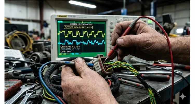
On the scope, the differential signal wasn’t the culprit. The CAN_H and CAN_L traces painted a textbook dominant-recessive picture — one line pulling to about 3.5 V, the other dropping toward 1.5 V, the differential voltage snapping past the 0.9 V threshold every time. What I should have been watching was the arithmetic mean of the two lines with respect to the ECU ground pin. When a J1939 backbone is terminated correctly with 120 Ω at each end and the bias circuit is healthy, that common-mode voltage sits stubbornly at 2.5 V whether the bus is dominant or recessive. Every training manual mentions it. Almost nobody puts a scope probe on it with the machine running.
The offset I found was 0.3 V. Not three volts, not a melted ground cable showing 1.5 V of drop, just three tenths of a volt difference between the ground plane of the engine ECU and the ground plane of the chassis node that hosted the instrument cluster and the transmission controller. On paper, 0.3 V is deep inside the allowable input common-mode window — the ISO 11898-2 specification says CAN transceivers must tolerate –2 V to +7 V — so why did the bus keep going silent? Because common-mode tolerance is a DC specification. Add switching noise from injector solenoids, alternator ripple, and the occasional ground current spike when the grid heater kicks in, and the instantaneous peak-to-peak noise riding on top of that 0.3 V DC shift would yank CAN_H and CAN_L outside the receiver’s valid range for a few microseconds. A few microseconds is all it takes to corrupt a CAN frame, increment the TEC (Transmit Error Counter), and, after enough consecutive errors, force the node into bus-off. Once the engine ECM hits bus-off, you lose torque messages, EGR data, fan speed commands, and suddenly the machine derates or shuts down entirely. After a key cycle, everything comes back clean — until the grid heater cycles again, or the alternator loads up, or a bucket strike momentarily flexes a corroded ground strap and shifts the potential just enough to repeat the event.
The diagnostic path that wasted seven thousand dollars before we even opened the junction box
What happens in most shops is predictable and completely rational if you skip the physical-layer measurements . Step one: read active faults, see J1939 loss-of-communication codes for the engine ECU, and assume the ECU itself has a failing CAN driver. A reman engine ECU gets installed — cost in the two thousand dollar range with programming, plus labor. Step two: problem returns after three operating hours. Now the technician suspects the wiring harness. A full OEM chassis harness is ordered, installed over two days — the harness alone often runs above fifteen hundred dollars, and the labor on a compact wheel loader can easily add another two thousand dollars. Step three: still no fix. The next target is the instrument cluster acting as a network gateway; it gets swapped and programmed at roughly one thousand dollars. We’re now approaching six thousand dollars in parts and labor, and the machine still drops out when hot. Step four: someone finally suggests “check all grounds.” A visual inspection of the engine ground cable looks fine — no corrosion, no loose lug. A resistance check with a handheld multimeter shows 0.2 Ω, which gets misread as acceptable because nobody compensates for the meter lead resistance or thinks about impedance under load. So the ground path is signed off as healthy, and the diagnostic loop resets. At this stage, a diesel technician who is excellent with wrenches but not trained in high-speed differential signaling will start replacing fuel system components and engine position sensors, chasing ghost misfires that only exist because the CAN data is corrupted.
In the case I walked into, the break came when I set up a four-channel oscilloscope with the machine running and the grid heater cycling. Channel 1 on CAN_H, Channel 2 on CAN_L, both referenced to the battery negative post. Channel 3 on CAN_H referenced to the engine ECU ground pin directly at the ECU connector. The differential signal looked clean on channels 1 and 2, but the moment I compared CAN_H referenced to ECU ground versus CAN_H referenced to chassis ground, the offset was unmistakable. During the grid heater pulse, the common-mode voltage measured at the ECU was sitting at 2.8 V, while at the chassis node it was at 2.5 V. A 0.3 V gap. That gap wobbled by another 100–150 mV of ripple in sync with the alternator field switching. The scope’s CAN trigger started showing occasional form errors — recessive-level violations where the bus didn’t return to the expected 2.5 V equilibrium quickly enough after the dominant phase, causing a bit-stuffing error that the controller flagged as a form error. Three form errors within a rolling window, and a warning flag turned into a bus-off state.
Root cause: it’s never just the cable
The voltage offset traced back to the engine ground return path. The engine block was connected to the frame through a dedicated ground strap — a braided copper flat strap, bolted to the engine block on one side and to a painted frame rail bracket on the other. The bolt threads were cutting through the paint, providing a small metal-to-metal contact patch that measured passable resistance when cold.
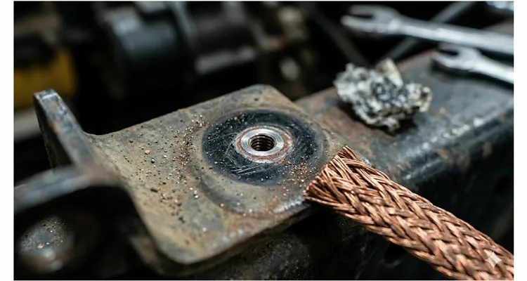
But the combination of engine vibration, thermal expansion, and oxidation on the contact face produced a semiconducting layer that behaved like a low-value resistor with a nonlinear temperature coefficient. As the engine bay heated up, that resistance rose, developing a voltage drop whenever current flowed from the engine block to the frame. The engine ECU, which sources its power and ground directly from the battery through the engine harness, sat at a slightly different ground potential than any module bolted to the chassis. The CAN transceivers were referencing their signals to two different “0 V” points, and the J1939 backbone became the unintended bridge between them.
The fix took less than two hours. We unbolted the ground strap, removed all paint from the frame-side bracket down to bright metal, applied a thin coat of corrosion-inhibiting electrical compound, torqued the bolt to spec, and added a supplementary ground cable directly from the battery negative terminal to a clean chassis stud near the central junction box. The 0.3 V offset disappeared; the common-mode voltage across all nodes stabilized at 2.5 V ±50 mV under all load conditions. The machine has accumulated over 2,000 hours since that repair with no communication faults.
How 300 millivolts turns a CAN transceiver deaf
Every CAN transceiver makes a simple decision: if the differential voltage (Vdiff) climbs above 0.9 V, the bus is dominant; if it drops below 0.5 V, it’s recessive. Those thresholds aren’t suggestions—they’re baked into the silicon, and a ground offset warps them. When the transmitting node’s local ground is offset from the receiving node’s ground, the CAN driver’s output transistors cannot pull the lines to the intended voltage levels relative to the receiver’s reference. The recessive level received at the far end may shift enough that, combined with ringing and reflections from an imperfect termination, the receiver samples an indeterminate logic level. This manifests as an ACK error, a CRC error, or a form error depending on which bit gets corrupted. Once the error counters reach their thresholds, the node isolates itself. In a J1939 network where a single ECU provides critical propulsion data, this is indistinguishable from a dead ECU — hence the cascade of unnecessary replacements. I have torn down a J1939 transceiver that was still communicating yet triggering intermittent bus-off events; the physical-layer degradation was invisible to a standard scan tool but plain as day on a four-channel scope.
Another subtlety is the shield ground if you are using shielded twisted-pair for the backbone. J1939/11 specifies that the shield should be grounded at only one point to prevent ground loops. In many off-highway installations, well-meaning technicians tie the shield to chassis ground at every bulkhead connector, creating multiple current paths that exacerbate any existing ground offset. I have seen machines where the shield was carrying nearly 200 mA of ground-loop current, turning the entire harness into an antenna for alternator noise. Disconnecting all but one shield drain connection dropped the bus error rate by an order of magnitude before we even fixed the primary ground offset.
The diagnostic sequence we use now (after getting burned once)
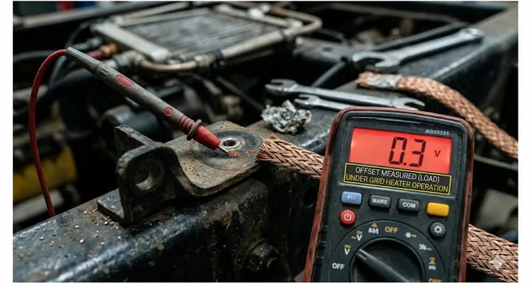
After the wheel loader incident, we changed the order we probe a misbehaving J1939 bus. We used to start with an ohmmeter across the ground straps — and that’s exactly why we missed the fault the first time. A handheld meter showing 0.2 Ω across an engine-to-frame strap means nothing once the grid heater pulls 300 A through that same bolt thread. Now we start with the machine running and a voltmeter on the millivolt scale, measuring between the battery negative post and the frame bracket near the backbone junction. On a clean ground plane, I want less than 50 mV. That loader showed only 85 mV at the engine block itself, but the real drop was buried at the frame-side bracket — a single bolted joint I would have skipped if I’d started with a static resistance check.
This voltage-drop field test catches more faults in five minutes than an ohmmeter finds all day.
Voltage-drop mapping under load
With the engine running and every available electrical load engaged — headlights, HVAC blower, work lights, grid heater — map the DC voltage between:
- Battery negative post and engine block
- Battery negative post and frame rail near the J1939 junction
- Engine block and firewall chassis ground
Use the millivolt scale. Anything above 50 mV on a high-current path demands attention. On the loader, the block-to-battery reading was only 85 mV, but the real offender was a single painted bracket on the frame side. If you only measure at the engine, you will miss it.
Four-channel scope capture
Once voltage drops are mapped, bring in the oscilloscope. A two-channel scope won’t cut it — you need at least four channels:
- Channel 1: CAN_H referenced to battery negative
- Channel 2: CAN_L referenced to battery negative
- Channel 3: CAN_H referenced to ECU ground pin (back-probed)
- Channel 4: (optional) CAN_L referenced to ECU ground, or a current clamp on the shield
Set the scope to AC-coupled, 500 mV/div. With CAN triggering enabled, look at the math trace (Ch3 mean). It should sit at 2.5 V ±0.1 V. A steady offset beyond 0.2 V that moves with electrical loads is the signature of a ground integrity problem — invisible to a multimeter.
Shield current measurement
Clamp the shield drain wire with a DC current probe. Any current flow means a ground loop. I’ve measured nearly 200 mA on some machines. Trace the harness and remove all but one shield-to-chassis connection — ideally the one nearest the battery negative reference. J1939/11 demands single-point grounding for a reason.
Dynamic load cycling
With the scope still on, cycle every high-current actuator: grid heater, AC compressor clutch, hydraulic solenoid banks. The common-mode voltage must stay within 0.2 V of 2.5 V during each transient. If you see a spike, you’ve found the circuit whose return path is lifting the ground reference.
Error frame logging
Finally, let the bus run for ten minutes under load while logging error frames. Use a scope with CAN decode or a dedicated CAN interface. A clean J1939 backbone should show zero error frames. On the wheel loader, we consistently counted three form errors before bus-off. That repeating pattern is the fingerprint of a ground offset that comes and goes with thermal cycling. If you’re capturing this with a USB scope, make sure you understand the edge rates and ringing that can masquerade as bit-sampling errors .
Common mistakes that prolong the nightmare
| Common Mistake | Why It Fails | What To Do Instead |
| Adding a third 120 Ω terminating resistor | Drops differential impedance, cuts signal amplitude, and makes the bus more sensitive to offsets | Verify exactly two terminations; measure ~60 Ω across CAN_H and CAN_L when unpowered |
| Spraying contact cleaner into Deutsch or Ampseal connectors | Sealed connectors rarely develop oxidation that causes intermittent bus dropouts | Focus on the ground path , not the signal connectors |
| Reloading ECU software to “clear corrupt firmware” | Wastes hours and resets adaptive values without touching the physical layer | Firmware corruption does not cause a 0.3 V ground shift |
| Ignoring the grid heater circuit during testing | The heater can pull hundreds of amps through a weak ground, creating a voltage shift that mimics a heat-related failure | Always cycle the grid heater while monitoring common-mode voltage |
Over the years, I’ve watched each of these missteps add thousands of dollars to repair bills that should have ended with a wire brush, a wrench, and a voltmeter. The genuine cost of ignoring the physical layer isn’t the diagnostic tools—it’s the unnecessary ECM replacements and the machines sitting idle while technicians swap parts the network never needed.
How to confirm the fix is durable
After correcting the ground paths, repeat the common-mode scope capture under the exact same load conditions that originally triggered the fault. The offset must return to below 0.1 V and stay there across the full operating temperature range from cold start to full-load heat soak. Record a baseline error-frame count and confirm it stays at zero. Then test the machine for at least three full heat cycles under loaded operation. Only then can you close the work order.
One habit that has served me well: after the repair, I deliberately introduce a temporary high-resistance connection — a 0.1 Ω power resistor in series with the ground strap, safely mounted — to confirm that the bus-off condition returns when the offset is reintroduced. This validates the root cause beyond doubt and prevents the “it just fixed itself” ambiguity that plagues intermittent network repairs. I remove the resistor before returning the machine to service.
From the field to the factory: how we build J1939 backbones that don’t drift
If you are an equipment OEM or a fleet maintenance engineer, the 0.3 V lesson has implications that go all the way back to harness design . A J1939 backbone is not a commodity you stamp out with a crimping tool and a continuity tester. The way ground attachment points are selected, how the shield is terminated, whether the factory tests each assembly for common-mode behavior under simulated load — these decisions matter far more than the copper gauge printed on the jacket.
We test every J1939 backbone assembly on a custom fixture that injects a 0.5 V ground offset between simulated nodes while monitoring the CAN bit error rate. That test isn’t required by any standard. We built it after seeing a single paint-insulated ground bracket cost a fleet nine thousand dollars. A cable that ships clean on a continuity tester can still generate form errors the first time a machine’s grid heater kicks in; our jig catches that before the cable leaves the factory. The assembly process feeding into that test is governed under IATF 16949 , and we store incoming terminal lots in humidity-controlled conditions because tin whiskers and oxide films on unseated crimps are ground-offset problems waiting to happen. ISO 9001 and ISO 14001 document the system, but the climate control, the four-step inspection, and the 100% end-of-line testing are what actually keep a 0.3 V ghost off your bus.
We have produced OEM-customized J1939 backbone cables for engine manufacturers, transmission control system integrators, and heavy equipment OEMs for over twenty years — working from unique specifications for length, AWG, connector pinouts, shield configurations, and even custom branding and jacket colors. When a customer asks for a specific cable length to avoid excess coiled harness that acts as an inductive pickup, or wants a jacket color that matches their brand identity, we engineer the solution from the conductor up, not from a catalog of pre-made SKUs. That level of control over the physical layer is often what separates a fleet that runs 10,000 hours without a network fault from one that chases intermittent J1939 ghosts every winter. Our connectors and overmolding use RoHS-compliant, full-plastic materials selected to resist galvanic interaction with chassis metals, and every assembly is 100% tested — not batch sampled, because the batch-sampling argument falls apart when a single untested cable can cost an end user nine thousand dollars in downtime.
If you are in the middle of a J1939 ground fault investigation , or if you are specifying backbones for a new vehicle program and want to get the physical layer right before the first prototype fires up, our engineering team can help you review your grounding topology, termination strategy, and harness routing. We do not see ourselves as a supplier of parts; we function as an extension of your engineering department for all things J1939 physical layer — from connector selection to full-harness validation.
We do not publish price sheets because none of this work is commodity. You can reach us through our Contact page at https://obd-cable.com/contact/ to describe what you are working on, or message our application engineering team directly on WhatsApp. We answer technical questions before we ever talk about lead times or order quantities.
WhatsApp: Chat with our engineers at https://api.whatsapp.com/send/?phone=8617307168662&text=Need+Help%3F+Chat+linda+WhatsAPP&type=phone_number&app_absent=0
Frequently Asked Questions
1. What is the acceptable common-mode voltage on a J1939 network?
The transceiver spec is generous — ISO 11898-2 allows –2 V to +7 V relative to the node’s local ground. But on the wheel loader that triggered this article, we were losing CAN frames with a DC offset of only 0.3 V. Why? Because the instantaneous peaks from alternator ripple and grid-heater switching were kicking the common-mode voltage far enough outside the receiver’s valid window to cause form errors, even though a DC voltmeter would have said the bus was within spec. In practice, I want the recessive common-mode voltage within ±0.1 V of 2.5 V on any J1939 backbone I sign off on. For a deeper dive, see our guide on diagnosing ground offset using common-mode voltage .
2. How do I measure the ground offset on a CAN bus without a differential probe?
Use two single-ended oscilloscope channels: one on CAN_H and one on CAN_L, both referenced to the battery negative post. Calculate the average using the scope’s math function. This gives you the common-mode voltage. Then move the probe ground to the ECU ground pin — back-probe it while the connector is plugged in — and measure again. The difference between the two common-mode readings is your ground offset . On the loader, it was 0.3 V, invisible to a differential probe.
3. Can a 0.3 V ground offset actually damage an ECU?
It rarely destroys hardware outright. The main risk is repeated bus-off events that cause the ECU’s CAN controller to temporarily disconnect from the network. Over many such events, the ECU may accumulate corrupted EEPROM data or suffer from repeated power-cycle stresses, but the primary cost is downtime and wasted replacement parts — nine thousand dollars on that loader, and not one smoked transceiver.
4. Why does the J1939 fault only happen when the engine is hot?
Thermal expansion opens microscopic gaps in a ground connection that relies on bolt-thread contact through paint. As the metals expand, contact resistance rises nonlinearly, developing a larger voltage drop. When the engine cools, the joint contracts and temporarily re-establishes a lower-resistance path. On our loader, the fault appeared after about forty-five minutes of operation, exactly when the frame bracket reached full heat soak.
5. Should I ground the J1939 shield at both ends?
No. Grounding the shield at more than one point creates a ground loop that can carry current — I’ve measured nearly 200 mA on some machines — turning the shield into a radiator for alternator noise. J1939/11 specifies a single-point ground, typically at the ECU or the junction box nearest to the battery. In the loader case, someone had grounded the shield at a bulkhead connector near the transmission, creating exactly the loop that amplified our 0.3 V offset.
6. What is the most common diagnostic mistake with intermittent CAN faults?
Replacing the engine ECU or the transmission controller before measuring the physical-layer signals under load . In my experience, well over half of “failed” ECUs returned for warranty analysis test perfectly on the bench because the fault was a ground offset, a bad termination, or shield current that only existed on the machine.
7. Can I use a multimeter to find the ground offset?
A multimeter can measure the DC voltage between the engine block and the battery negative under load, which is a useful quick check — we found 85 mV at the block on the loader, a clue we almost ignored. However, a multimeter cannot show you the dynamic common-mode fluctuations caused by switching loads, nor can it reveal CAN form errors. An oscilloscope is essential for a conclusive diagnosis.
8. What resistance is acceptable for an engine ground strap?
Ideally less than 1 mΩ when measured with a four-wire method. Anything above 10 mΩ between the engine block and the battery negative terminal under static conditions is suspect. But remember, our loader’s ground strap showed 0.2 Ω on a two-wire meter and was signed off as healthy. Resistance values change under vibration and heat — a “good” cold reading can turn bad during operation.
9. If I fix the ground offset, do I need to re-terminate the J1939 backbone?
Not unless the termination resistors were disturbed or damaged during the repair. However, you should verify that both termination resistors are present and measure roughly 60 Ω when the network is unpowered. On the loader, one of the terminations had been removed during the harness swap and never reinstalled, which made the bus even more sensitive to the ground offset. We’ve seen fleets burn through over fifteen thousand dollars in maintenance costs from similarly overlooked termination mistakes.
10. Can the factory that builds the J1939 harness prevent these problems?
Yes, absolutely. A harness manufacturer that understands CAN physical-layer requirements will design the grounding scheme correctly from the beginning, select proper connector plating to avoid galvanic potentials, verify shield integrity, and test the finished assembly under simulated ground-offset conditions . That last step — testing with a deliberate 0.5 V offset while monitoring for bit errors — is what catches the 0.3 V ghost before it ever reaches the field. It’s a test we built after watching a single painted bracket drain nine thousand dollars from a fleet budget, and it runs on every J1939 backbone that leaves our floor.
